Basics of loading machines
Circuit Breaker
The main functions of circuit breakers are to activate and open electrical circuits. The latter process is initiated when the voltage drops seriously below normal, the circuit becomes overloaded, or a short circuit incident occurs. When technicians load machines, their goal is to check the correct functioning of the releases by passing an electric current through them coming from a specially designed installation.
Situations in which this procedure is recommended include:
- overhaul of a switch or other electrical equipment;
- purchasing a new device;
- completion of electrical installation repairs.
Circuit breaker loading diagram
Planned preventative loading is also carried out at a certain frequency established at the enterprise.
The mechanism of the procedure is based on the action of an electromagnet on the release, as a result of which the latter is activated and the device stops working. A correctly organized procedure will make it possible to determine whether the device is capable of protecting the network from various kinds of unpleasant incidents. It must protect against fire and excessive loads (frequent phenomena due to damage to the insulating material of wires and pressure changes) and against the user receiving an electric shock in a short-circuited circuit. If the device has passed the tests, it is considered to be in good working order and suitable for routine use.
Why is it necessary to load current machines?
A current value that differs significantly from the calculated value almost always indicates a malfunction of the electrical installation. An increase in energy consumption can be caused by the gradual destruction of electrical circuit elements, installation or switching errors, or a short circuit.
Testing circuit breakers with an artificially created abnormal current (overcurrent) is called loading the circuit breaker. It helps to determine whether the power supply will be interrupted in a timely manner (circuit break) before serious consequences arise when the electrical circuit is overloaded, since:
- overcurrent leads to overheating of the conductor, which threatens it with fire or causes damage to electrical equipment;
- The greatest danger is represented by short circuits, in which charges may appear on the housings of electrical equipment, whose potentials threaten human health.
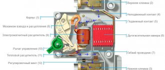
Main characteristics of circuit breakers
Circuit breakers belong to the category of protective devices. They protect the electrical circuit from the consequences of a short circuit: when an incident occurs, the device must immediately turn off to avoid sparking or burning. For electrical equipment, different types of machines are used, suitable for technical characteristics. To operate with voltages less than 1000 V, switches with a molded case (withstand current up to 3.2 kA), air power switches (critical indicator - 6.3 kA), as well as devices with a modular structure are used.
All switches are equipped with two protective releases located inside the body of the electrical device. Electromagnetic protects against a short-circuit situation, and thermal provides protection for equipment and electrical circuits from excess load.
The main characteristics of the devices include:
- operating current - the value at which the switch is activated in the event of an overload or short circuit;
- time interval after which the device is triggered;
- rated current value at which the device can operate in normal mode.
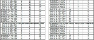
Time-current characteristics of automatic circuit breakers AP-50
During the loading procedure, these indicators are measured.
The procedure cannot be called simple; only highly qualified electrical laboratory personnel are allowed to implement it after undergoing special training.
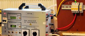
Loading circuit breakers using special equipment
In order for the machine to be loaded automatically, special equipment must be used for these purposes. This action will take several minutes. During the operation, the status of the work can be assessed. Based on the requirements of the rules, the calculation method is not suitable for this, since it results in a large error.
Along with the information that the device is working properly, other important values are also examined:
- duration of contacts;
- wiring integrity;
- there are problems with the DC supply.
Test Methods
Although information is made available locally, maintenance is carried out to eliminate defects. Measurements are carried out of basic and additional parameters in order to compare them with standards and get rid of the defect. The loading sequence is the same for all devices.
Thus, by carrying out all measures to check the devices, safety can be achieved during further operation. It is always better to prevent an emergency, which is why loading was developed.
AB loading device
LATR
The method of loading circuit breakers involves the artificial creation of a closed circuit with the option of gradually adjusting the electric current indicator. This principle is used by any commercially available vending machine loader. There are devices designed for different rated currents.
You can assemble the installation yourself. One example is a design using three types of transformer devices: one of them is responsible for the load, the other works with electric current, and the third is a laboratory automatic device. The circuit also includes a shunt ammeter, control switch, stopwatch and cables. The function of the latter is to connect the switch being tested to the controlled current terminals. This design can create a current of about 50 A on the secondary coil of the load transformer. It can also be used to test switches designed for high current values, but then a power source and a high-power load device will be required.
Method of loading machines
Loading of machines is done according to a single algorithm. First you need to study the technical documentation of the device and determine the characteristics that need to be checked. Then the functioning of the releases is tested: first they always work with the electromagnetic unit, then with the thermal one. Then the results are recorded in a prepared protocol on the work performed.
Example
Installation of an extended terminal from studs
The procedure can be demonstrated using the example of a switch from the domestic manufacturer BA47-29. The protection class of this device is C, which corresponds to the need for five times the rated current (which here is 6 A) for the electromagnetic protection to operate. This degree of protection is most common for switches used in ordinary household networks.
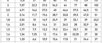
Before connecting the device to the test installation, you need to study the technical documentation supplied with it. It contains a graphical representation of the time-current response characteristic. The abscissa axis represents the loading current exceeding the nominal value. The y-axis is the time period after which the thermal protection is activated.
Load supply
Having studied the graph, you can understand that the zone in which the electromagnetic release is triggered covers the range of exceeding the rated electric current (6 A) by 5-10 times. Thus, to turn on this type of protection, a current of 30-60 A will be required. This mechanism operates almost instantly: if it works properly, the time should not exceed 0.02 s. For practical experience, you can take an eightfold excess (48 A), in this case the machine should be turned off from the network no later than after 0.01 s.
As for the thermal protection mechanism, the graph limits the switching interval to a pair of curves representing the normal and hot states of the switch. Three times the rated current (18 A) will be used for testing. The use of electric current of this frequency ratio for testing is a traditional indicator, unless there are indications of a different recommended frequency ratio in the device passport. The time value after which the machine will turn off must be in the range from 3 to 80 s (this can be found on the schedule).
When any of the releases does not turn off the device within the required time frame, the switch is considered faulty and is not allowed for subsequent operation. To make it easier to load the device, you can put long leads made from pins on it. Cables are connected to them.
Loading Features
Loading an industrial circuit breaker with a generator
Electromagnetic loading of circuit breakers operates according to the following principle:
- The electromagnet has a specific effect on the release;
- The release is activated;
- The machine stops working.
Important! The essence of the process is to check the quality and performance of the releases, which is performed by passing current through the structure of the machine. The current is diverted from the appropriate installation responsible for testing.
Hello. Recently we checked the operation of circuit breaker releases using the Saturn M2 device. The device is new, recently purchased and not yet fully mastered. Switches Schneider electric iC60N, characteristic C, different ratings. During the inspection, the type of switch was determined to be “household”. There were no issues with the thermal releases; they work as they should in accordance with GOST 50345-2010. Instantaneous releases on some machines were triggered at current values greater than the setting currents of the releases. For iC60N automatic machines with characteristic C, the instantaneous release setting is 6.4In - 9.6In. For example: a machine with a rated current of 6A (setting 38-58A) was triggered at a current of 72A, time 0.018 s (less than 0.1 s - corresponds to GOST). The 63A circuit breaker (set 403-605A) operated at a current of 796A, time 0.008 s. Similar results were obtained for both DPN Vigi and EZC industrial circuit breakers. How to interpret such measurement results? How do circuit breakers malfunction? Tell me, owners of Saturns, what currents do you get when taking measurements?
Where did you get this range from? Did you come up with it yourself or did the manufacturer indicate it in the documentation? If the circuit breaker complies with GOST 50345-99, then the current range should be in the range 5-10In.
The measurement technique is described in detail in the book by A.V. Sakara ORGANIZATIONAL AND METHODOLOGICAL RECOMMENDATIONS FOR TESTING ELECTRICAL EQUIPMENT AND DEVICES OF CONSUMER ELECTRICAL INSTALLATIONS
Read Chapter X. TESTING OF CIRCUIT BREAKER RELEASES
This chapter, among other things, describes the method for measuring the characteristics of circuit breakers using the Saturn device. You have a new model Saturn, see the instruction manual.
The machines do not comply with GOST requirements.
Rated current - 10 A Setting of releases: overload - 10 short circuit - 50-100 Duration of application of test current - 0.2 test failure current - 50 Test response current - 76 Release response - (+)
Of course we’re not making anything up). According to the current-time characteristic of the iC60N Schneider electric circuit breakers, characteristic C.
Of course it's a malfunction. Do you have any doubts? Were the measurements carried out operational? The device has been verified, negative readings have been recorded, write (-).
There are doubts. Schneider electric, after all, and cases of non-compliance are not isolated. Maybe something is wrong with the device, or we are doing something wrong. We need to figure it out. I'm going to write to Radius.
Depends on the operating mode. Maybe they were completely raped. I carry out measurements with the UPTR-2MC device at a facility where only ABB circuit breakers were installed, and out of 100 pieces, 15 do not correspond. The device is working properly, we constantly check it, but the machines are not working.
How can you do it wrong? Are some right and others wrong?
Call them, it will be faster.
I would also call Schneider. Let them explain how the time-current characteristics of the machines correspond to the requirements of the standard that is indicated. IEC/EN 60898 is GOST R 50345-2010 (IEC 60898-1:2003). See Table 2 - Instantaneous Trip Current Ranges.
See what the manufacturer writes in the catalog and what standard it refers to:
Protocol and frequency of loading
Before starting testing, it is advisable to make a protocol header in which the results will be recorded. The document specifies the following parameters:
- specified time delay values;
- types of tested releases;
- response time of each of the studied protections;
- short circuit and overload current values;
- exposure time of each current;
- current values at which the device operates and remains static;
- features of defense reactions during testing events.
Protocol page 1
Protocol page 2
If the data obtained corresponds to the established standards, the device is recommended for commissioning. If malfunctions are identified during loading operations, a special document is prepared indicating the nature of the violations and recommendations for their elimination in accordance with the PUE.
Periodicity
The Rules for the Construction of Electrical Installations, as well as the Rules for the Technical Operation of Consumer Electrical Installations, do not in any way regulate the frequency of scheduled testing. However, regular loading at regular intervals is advisable, since machines tend to exhaust their resource over time. In the passport or other documentation attached to the device, the manufacturer indicates the recommended intervals between tests. In production, such periods are set by the technical manager. Most often, elective procedures are recommended every three years. This applies to devices installed in industrial electrical networks and used for domestic needs. Additional checks are carried out when installing new equipment or overhauling old equipment.
Regular downloading of these machines will allow you to quickly determine the malfunction of the device. This will prevent disruptions to the functioning of electrical networks.
What regulatory documents are used when developing verification algorithms?
- Basic terms and definitions, as well as basic regulatory ranges used to describe the characteristics of tripping machines, are given in the GOST 50031-2012 standard.
- Specific testing algorithms and recommended bench test schemes are given in GOST R 50345-2010 (as well as in section 8 of GOST R 50030.2-99).
- Insulation resistance is measured in accordance with the PUE (clause 1.8.37.3) and PTEEP (Appendix 3.1, table 37).
- The organization of measurement conditions is carried out in accordance with the above standards and taking into account the provisions of industry SNIP.
Despite the fairly clear regulatory development of algorithms for revision and adjustment of equipment for overcurrent protection, for each specific case, its own version of the technological instructions is developed, usually focused on a specific type of release and available measuring equipment.
Electrical laboratory "Mega.ru" provides services for organizing and conducting all types of tests in electrical installations, including comprehensive testing of circuit breakers. You can clarify prices and place an order for specialists to visit you by calling the numbers published on the “Contacts” page.