Protective characteristics of C, B and D machines
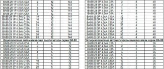
We supply BA47‑29 circuit breakers with rated currents from 0.5 to 63 amperes with protective characteristics B, C or D.
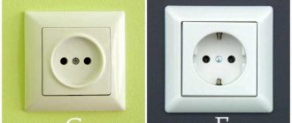
Introduction
- to protect networks: from short circuits - an electromagnetic release is built in for this purpose;
- from overloads - a thermal release is built in for this purpose;
A thermal and electromagnetic release is installed in each pole of the machine and together they are called a combined release.
Characteristic C, B or D determines the strength of the short-circuit current at which instantaneous protective operation will occur, and therefore the places where the machine with a specific characteristic will be used. The operation is caused by an electromagnetic release.
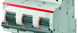
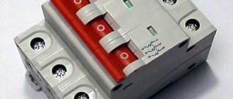
On the left is a photograph of VM63 modular switches with an analysis of the inscriptions (“what is what”).
Differences between circuit breakers with characteristics B, C and D
| Type of protective characteristic | Instant shutdown in case of short circuit out of range | Preferred Circuit Breaker Application | Loads |
| B | (3-5)In |
| resistive |
| C | (5-10)In |
| resistive, inductive with low inrush current |
| D | (10-50)In |
| inductive with high starting current |
where In is the rated current of the circuit breaker.
Examples:
- A circuit breaker with a rated current In = 6 amperes with characteristic B: will not trip* with a short circuit of 18 amperes (3·In), but will switch off instantly with a short circuit of 30 amperes (5·In) and above.
- A circuit breaker with a rated current In = 16 amperes with characteristic C: will not trip* with a short circuit of 80 amperes (5·In), but will switch off instantly with a short circuit of 160 amperes (10·In) and above.
- A circuit breaker with a rated current In = 50 amperes with characteristic D: will not trip* with a short circuit of 500 amperes (10·In), but will turn off instantly with a short circuit of 2500 amperes (50·In) and above.
*By the words “will not work” we mean will not work under the influence of an instantaneous electromagnetic release. But there is a thermal release that will heat up within a few seconds and turn off the network.
At the same time, the standard does not indicate how the switch will behave in the range itself (the error is included). Tests are carried out only in boundary positions (according to table 6 on page 19 of the GOST 50345‑99 standard):
- lower limit (3, 5 and 10 from In, respectively) – shutdown does not occur within 0.1 seconds;
- upper limit (5, 10 and 50 from In, respectively) – protective operation occurs within 0.1 seconds.
Circuit breaker characteristic B
- long cable lines;
- circuits with a heating element (heating element, electric oven, boiler);
- secondary circuits or networks with high resistance and low current (which causes low-level short-circuit currents): alarms;
- management;
- measurements.
Characteristic C of circuit breaker
- apartment and office sockets;
- lighting in the kitchen, bedrooms; in the bathroom, in the office, in the workplace;
- individual consumers (without powerful engines).
Characteristic D of the circuit breaker
- washing machines;
- dishwashers;
- pumps for drinking water intake;
- welding machines.
Why are only machines with characteristic D suitable? At the moment the electric motor starts, starting currents appear that are 5-7 times greater than the rated (operating) current. After acceleration, the current consumption is equal to the rated current. If you install a switch with characteristic C (short circuit shutdown in the range of 5-10 rated current values), it will “confuse” the starting current with a short circuit and turn off the network. To prevent false alarms, switches with protective characteristic D are used.
Design and principle of operation of a circuit breaker.
The figure below shows the design of a circuit breaker with a combined release, i.e. having both an electromagnetic and thermal release.
- 1 - body;
- 2,3 - lower and upper screw terminals for connecting the wire;
- 4 - fixed contact;
- 5 - moving contact;
- 6—arc chamber;
- 7 - flexible conductor (used to connect moving parts of the circuit breaker);
- 8 - cocking and release mechanism
- 9 — electromagnetic release coil;
- 10 — control lever;
- 11 — thermal release (bimetallic plate);
- 12 — adjusting screw;
The blue arrows in the figure show the direction of current flow through the circuit breaker.
The main elements of the circuit breaker are electromagnetic and thermal releases:
The electromagnetic release provides protection of the electrical circuit from short circuit currents. It is a coil with a core located in its center, which is mounted on a special spring. In normal operation, current passing through the coil according to the law of electromagnetic induction creates an electromagnetic field that attracts the core inside the coil, but the strength of this electromagnetic field is not enough to overcome the resistance of the spring on which the core is installed.
During a short circuit, the current in the electrical circuit instantly increases to a value several times higher than the rated current of the circuit breaker; this short circuit current, passing through the coil of the electromagnetic release, increases the electromagnetic field acting on the core to such a value that its retraction force is enough to overcome the resistance springs, moving inside the coil, the core opens the moving contact of the circuit breaker, de-energizing the circuit:
In the event of a short circuit (i.e., with an instantaneous increase in current several times), the electromagnetic release disconnects the electrical circuit in a fraction of a second.
The thermal release protects the electrical circuit from overload currents. Overload can occur when electrical equipment is connected to the network with a total power exceeding the permissible load of this network, which in turn can lead to overheating of the wires, destruction of the insulation of the electrical wiring and its failure.
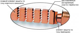
The thermal release is a bimetallic plate. Bimetallic plate - this plate is soldered from two plates of different metals (metal “A” and metal “B” in the figure below) having different coefficients of expansion when heated.
When a current exceeding the rated current of the circuit breaker passes through the bimetallic plate, the plate begins to heat up, while metal “B” has a higher expansion coefficient when heated, i.e. when heated, it expands faster than metal “A”, which leads to curvature of the bimetallic plate; by bending it affects the release mechanism, which opens the moving contact. In a simple diagram it looks like this:
The response time of the thermal release depends on the amount of excess current in the electrical network of the rated current of the machine; the greater this excess, the faster the release will operate.
As a rule, the thermal release operates at currents 1.13-1.45 times higher than the rated current of the circuit breaker, and at a current 1.45 times higher than the rated current, the thermal release will turn off the circuit breaker in 45 minutes - 1 hour.
The operation time of circuit breakers is determined by their time-current characteristics (VTC)
Whenever a circuit breaker is turned off under load, an electric arc is formed on the moving contact, which has a destructive effect on the contact itself, and the higher the switched current, the more powerful the electric arc and the greater its destructive effect. To minimize damage from an electric arc in a circuit breaker, it is directed into an arc-extinguishing chamber, which consists of separate, parallel-installed plates; when the electric arc falls between these plates, it is crushed and extinguished.
Circuit breaker device
A circuit breaker (in the language of electricians, “automatic”) is the basis of protection in low-voltage (up to 1000 Volt) power electrical circuits. This is a combined electrical device that combines the functions of a switch and a protective device. Almost the entire distribution and protection system for household electrical wiring is built on automatic devices. I would like to immediately note that the main use of the machine is to protect that section of electrical wiring that is located between the outlet of the machine and the consumer. If there is another machine further along the line, then our machine must defend the area between these two machines. If an overload or short circuit occurs in any section of the circuit, only one circuit breaker should operate, protecting that particular section of the circuit.
Circuit breaker design
The circuit breaker consists of two releases - a thermal release and an electromagnetic release.
The thermal release is a bimetallic strip. When current flows, the plate heats up and changes its shape (bends). Thus, when a current flows that exceeds the rated current of the machine, the bimetallic plate bends so much that the machine turns off. When you turn on the machine, the spring is charged and it is fixed by a lever, which locks the machine in the on position. This very lever removes the bimetallic plate.
The electromagnetic release is designed for short circuit protection. During a short circuit, a current flows in the cable that is several times higher than the rated current of the machine. This current must be turned off immediately. For this, the mechanism of the machine uses an electromagnet - a coil and a core. When current flows, the coil retracts the core, which presses the locking lever and thus actuates the trip mechanism.
Characteristics of switches and their groups
There are several important characteristics of an automatic machine based on which an automatic machine is selected for different loads. One of them is the response characteristics of circuit breakers.
Graph No. 1 shows the difference in time current characteristics of the 3 main groups of machines
The characteristic curve shows how the response time of the machine varies from the ratio of the current through the contacts of the machine to its rated value. The dependence line is displayed graphically. For example, circuit breakers of the same rating with different characteristics of the circuit breaker curves have different shutdown times. Also in graph No. 1, the coverage areas of the thermal protection and electromagnetic protection of the circuit breakers are marked with rectangles.
Selecting a circuit breaker
The choice of machine is carried out according to the following criteria:
— By the number of poles: one- and two-pole are used for a single-phase network, three- and four-pole are used in a three-phase network.
— By rated voltage: The rated voltage of the circuit breaker must be greater than or equal to the rated voltage of the circuit it protects: U nom. AB ⩾ U nom. networks
— By rated current: You can determine the required rated current of the circuit breaker in one of the following ways:
- Circuit breaker power calculator by rated current
- Using one of the following tables:
Selection of circuit breaker by power:
| Connection type | Single phase | Single-phase input | Three-phase delta | Three-phase star |
| Machine polarity | Single-pole circuit breaker | Two-pole machine | Three-pole machine | Four-pole circuit breaker |
| Supply voltage | 220 volt | 220 volt | 380 Volt | 220 volt |
| Automatic 1A | 0.2 kW | 0.2 kW | 1.1 kW | 0.7 kW |
| Automatic 2A | 0.4 kW | 0.4 kW | 2.3 kW | 1.3 kW |
| Automatic 3A | 0.7 kW | 0.7 kW | 3.4 kW | 2.0 kW |
| Automatic 6A | 1.3 kW | 1.3 kW | 6.8 kW | 4.0 kW |
| Automatic 10A | 2.2 kW | 2.2 kW | 11.4 kW | 6.6 kW |
| Automatic 16A | 3.5 kW | 3.5 kW | 18.2 kW | 10.6 kW |
| Automatic 20A | 4.4 kW | 4.4 kW | 22.8 kW | 13.2 kW |
| Automatic 25A | 5.5 kW | 5.5 kW | 28.5 kW | 16.5 kW |
| Automatic 32A | 7.0 kW | 7.0 kW | 36.5 kW | 21.1 kW |
| Automatic 40A | 8.8 kW | 8.8 kW | 45.6 kW | 26.4 kW |
| Automatic 50A | 11 kW | 11 kW | 57 kW | 33 kW |
| Automatic 63A | 13.9 kW | 13.9 kW | 71.8 kW | 41.6 kW |
Selection of circuit breaker according to the cross-section of cable cores:
| Cable cross-section, sq.mm | Rated current of the machine, A | Power of 1-phase load at 220V, kW | Power of 3-phase load at 380V, kW | |
| Copper | Aluminum | |||
| 1 | 2.5 | 6 | 1.3 | 3.2 |
| 1.5 | 2.5 | 10 | 2.2 | 5.3 |
| 1.5 | 2.5 | 16 | 3.5 | 8.4 |
| 2.5 | 4 | 20 | 4.4 | 10.5 |
| 4 | 6 | 25 | 5.5 | 13.2 |
| 6 | 10 | 32 | 7 | 16.8 |
| 10 | 16 | 40 | 8.8 | 21.1 |
| 10 | 16 | 50 | 11 | 26.3 |
| 16 | 25 | 63 | 13.9 | 33.2 |
— Selecting the response characteristic : often the response characteristic of a circuit breaker is selected based on the purpose of the network it protects (according to the table of response characteristics above), however, a machine selected in this way may not ensure timely shutdown of the circuit in the event of a short circuit; the response characteristic must be determined according to the method given here.
Source
Basic principles of operation of residual current circuit breakers
Let's start with the electrical network, which is protected by a circuit breaker, the characteristics of which directly depend on the parameters of the protected section of the network. The task of the machine is to control the current parameters in this circuit, avoiding overloads, and immediately turn off the section if the wires overheat or short circuit, and also if the current exceeds the permissible threshold values. Thus, between the point at which your object is connected to the power system and the device that consumes energy, there are two main elements. The first is a circuit breaker, the characteristics of which are associated with the second - the cable (wires), more precisely with the number of cores and the cross-section of this cable. Here are 2 simple examples:
In the hallway there are several light bulbs with a total power of 400 watts and a section of heated floors with a power of 1500 watts. The network is 220 volts, which means (Watt = Volt x Ampere), 1400 Watt divided by 220 volts equals 8.4 Amperes. That is, to protect this area, a machine with a current of 8.4 Amperes is sufficient, but we set it to 10 A.
We advise you to study the Vector diagram of currents and voltages
The kitchen has 10 appliances with a power of 1200 watts, and a total of 12000 watts. Therefore, for this section: 12000 divided by 220 - you need 54 Amperes, but we limited ourselves to a standard 25 Ampere machine.
To understand the principle of operation of circuit breakers, these examples are sufficient.
In the hallway, the machine will most likely turn off only when a short circuit occurs in the circuit. The probability of a shutdown due to overload or overheating of this section of the network is negligible (if the parameters of the current coming from outside remain unchanged)
There are also no special requirements for the cross-section of wires in this section.
Attention! In this hallway, given as an example, there are no sockets for connecting other appliances!
But in the kitchen, turning on appliances one after another will lead to the following situation:
Each switched on device (+1200 watts) will increase the load, and therefore the current strength in this circuit. The switched on 5th device will increase the current strength to: 5*1200/220=27.3 A.
The machine “knows” that the current strength in this area cannot exceed 25 Amperes. Therefore, turning on the 5th appliance will lead to the kitchen being disconnected from the network. (Let us clarify if the characteristics of the machine are 1 to 1, as discussed below).
Advice. If the circuit breaker trips, consider the last action (turning on the iron, for example), turn off the devices in the de-energized area (preferably by removing the plugs from the sockets), and only after making sure that everything is turned off, after waiting ten minutes (so that the overheated fuse elements cool down), try it turn on again.
So, the machine, having detected an excess of the current parameter, de-energized a section of the network. What happens if there is a short circuit in the kitchen? A short circuit leads to a sharp increase in load and an instant increase in current. In this case, the wires become heating elements, heating up to high temperatures. Heating occurs simultaneously in the entire circuit through which current flows. In this case, the current strength can instantly increase to very large values. This can lead to burnt contacts and an inevitable fire if the timing of the circuit breaker is incorrect.
Having considered the above, you will easily understand the remaining characteristics of the machines, how to “read” them, as well as the basic principles of operation of circuit breakers, including those for industrial use.
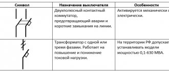
Designations and types of current switches
On the front panel of the overcurrent circuit breaker there are several symbols that define the parameters of the overcurrent relay:
C2 is the most important parameter of the circuit breaker. The first letter, in this case "C", determines the characteristics of the switch, and "2" - the rated current
The current value is, of course, indicated in Amperes.
~ 230 / 400V is the second most important parameter. This is the electrical voltage that the switch is designed to handle.
Circuit breakers designed for alternating current can also be used in dc systems, but their characteristics for alternating current and direct current are different.
6000 in the box - the value means the maximum current that can flow through the switch for it to still work correctly. 6000A is a really high current and at home it is almost impossible to get such a value even with a short circuit.
3 in the box - class of energy limitation caused by a short circuit. This is the highest class, and such overcurrent switches are rarely encountered; they are usually of a lower class.
FAEL and S301 - manufacturer and product code (designation depends on manufacturer standards).
Overcurrent switches can not only be single (1P), but can also have 2, 3 or 4 elements.
The switch for multi-position switches is general, that is, only two states are possible: all circuits connected to the circuit breaker are on or all circuits are off. This makes sense, for example, using a three-position circuit breaker for three-phase devices, where if a short circuit or overload is detected on any single-phase conductor, the entire device will be de-energized.
Triggering characteristics
The sensitivity of electromagnetic releases is regulated by a parameter called the response characteristic. This is an important parameter, and it’s worth dwelling on it a little. The characteristic, sometimes called a group, is denoted by one Latin letter; on the body of the machine it is written right before its nominal value, for example, the inscription C16 means that the rated current of the machine is 16A, characteristic C (the most common, by the way). Less popular are machines with characteristics B and D; current protection of household networks is mainly based on these three groups. But there are machines with other characteristics.
According to Wikipedia, circuit breakers are divided into the following types (classes) based on instantaneous tripping current:
- type B
: over 3
I n
up to 5
I n
inclusive (where
I n
is the rated current) - type C
: over 5·
I n
up to 10·
I n
inclusive - type D
: over 10·
I n
up to 20 ·
I n
inclusive - type L
: over 8
I n - type Z
: over 4
I n - type K
: over 12
I n
At the same time, Wikipedia refers to GOST R 50345-2010. I specifically re-read this entire standard, but it never mentions any types L, Z, K. And for some reason I don’t see such machines on sale. For European manufacturers, the classification may be slightly different. In particular, there is an additional type A
(over 2·
I n
to 3·
I n
).
Some manufacturers have additional shutdown curves. For example, ABB
has circuit breakers with curves
K
(8 - 14 ·
I n
) and Z (2 - 4 ·
I n
), corresponding to the IEC 60947-2 standard. In general, we will keep in mind that, in addition to B, C and D, there are other curves, but in this article we will consider only these. Although the curves themselves are the same - they generally show the dependence of the response time of the thermal release on the current. The only difference is the point to which the curve reaches, after which it abruptly ends to a value close to zero. And here are the graphs themselves:
These are average graphs; in fact, some variation in the response time of thermal protection is allowed. What should we keep in mind when choosing a shutdown characteristic? Here the starting currents of the equipment that we are going to turn on through this machine come to the fore.
It is important for us that the starting current in sum with other currents in this circuit does not exceed the operating current of the electromagnetic release (cut-off current). It’s easier when we know exactly what will be connected to our machine, but when the machine protects a group of sockets, then we can only guess what and when it will be turned on
We advise you to study Current Frequency
Of course, we can take it with a reserve - install group D machines. But it is far from a fact that the short circuit current in our circuit somewhere on a distant outlet will be sufficient to trigger the cutoff. Of course, after ten seconds the thermal release will heat up and turn off the circuit, but this will be a serious test for the wiring, and a fire may occur at the point of the circuit. Therefore, we need to look for a compromise. As practice has shown, to protect sockets in residential premises, offices - where the use of powerful power tools and industrial equipment is not expected - it is best to install automatic machines of group B. For the kitchen and utility unit, for garages and workshops, automatic machines with characteristic C are usually installed - there , where there are sufficiently powerful transformers and electric motors, there are also starting currents. Group D machines should be installed where there is equipment with difficult starting conditions - conveyors, elevators, hoists, machine tools, etc.
Look at the following picture, very similar in meaning to the previous one; here you can see the spread of thermal protection parameters of circuit breakers:
Notice the two numbers at the top of the graph. These are very important numbers
1.13 is the multiplicity below which no serviceable machine will ever work. 1.45 is the multiplicity at which any working machine is guaranteed to work. What do they actually mean? Let's look at an example. Let's take a 10A machine. If we pass a current of 11.3A or less through it, it will never turn off. If we increase the current to 12, 13 or 14 A, our machine may turn off after some time, or it may not turn off at all. And only when the current exceeds 14.5A can we guarantee that the machine will turn off. How fast depends on the specific instance. For example, with a current of 15A, the response time can range from 40 seconds to 5 minutes. Therefore, when someone complains that his 16-amp circuit breaker does not work at 20 amperes, he does it in vain - the circuit breaker is absolutely not obliged to work at such a frequency. Moreover, these graphs and figures are normalized for an ambient temperature of 30°C; at lower temperatures the graph shifts to the right, at higher temperatures - to the left.
Circuit breaker testing
The standard provides for the following tests:
- The initial state of the machine is “cold”, i.e. no current was passed through it before. A current of 1.13•Inom is passed through the machine.
- The initial state of the machine is immediately after test “a”. A current of 1.45•Inom is passed through the machine.
- The initial state of the machine is “cold”. A current of 2.55•Inom is passed through the machine.
- The initial state of the machine is “cold”. of the lower is passed through the machine (3•Inom for “B”, 5•Inom for “C”).
- The initial state of the machine is “cold”. of the upper is passed through the machine (5•Inom for “B”, 10•Inom for “C”).
The result of test “a” is the absence of operation of the machine for a time t>1 hour for machines with a rated current Inom≤63A and t>2hours for machines with Inom>63A.
The result of test “b” is the operation of the machine in time t 63A.
The result of test “c” is the operation of the machine within 1s 32A.
The result of test “d” is the operation of the machine with characteristic “B” within 0.1s 32A; with characteristic “C” within 0.1s 32A.
The result of test “e” is that the circuit breaker operates in time t and is guaranteed to be performed only if the short-circuit current exceeds the upper limit of the operation range, i.e. 5•Inom for characteristic “B”, 10•Inom for characteristic “C”, 20•Inom for characteristic “D”. These trip rates should be used when checking the tripping time of a circuit breaker for a single-phase short circuit.
Source
Connecting overcurrent protection
The diagrams are diagrams, but in the end you need to take a screwdriver and connect the wires to the electrical panel. Let's start by removing the insulation from the end of the wire. The insulation removed must be of sufficient length. Too short insulation means, firstly, a smaller contact surface of the switch with the cable, and secondly, the risk of screwing the fastener onto the insulation instead of the bare wire. Correct tip length: 10-15 mm.
Secondly, you need to insert the wire where it should be. The cable must be between the movable clamp and the top of the hole. The problem, despite its simplicity, can be real. Most often they look at the switch from the front, so they cannot see the terminals and it is easy to make a mistake.
The terminals on both sides of the switch function the same. Connecting two wires to a circuit breaker is possible provided that both wires have the same cross-section. Trying to connect wires with different cross sections is not recommended.
A thinner wire may jump out of the mount during operation. In the above pictures there are two wires connected: brown 2.5mm2 and black 1.5mm2.
Changing the release characteristics of automatic machines
As mentioned at the beginning of the article, all characteristics of safety circuit breakers are given at an ambient temperature of 30 degrees Celsius. In order to find out the response time of mechanical switches at other temperatures, the following correction factors should be taken into account:
1.Kt – temperature coefficient of ambient air. You can analyze its values in the graph below. The higher the air temperature, the lower the value of this coefficient, which means the rated current of the switch, that is, its load capacity, decreases. Or, in other words, the colder it is, the lower the load capacity. For this reason, in hot rooms it is possible for the circuit breakers to operate even without an increase in load.
2.Kn – coefficient for taking into account the number of machines installed in a row. When several circuit breakers are installed in one row, they transfer part of their heat to the remaining switches. The graph below shows the dependence of heat convection on the number of machines. The more devices in a row, the less their load capacity.
In order to calculate the electric current, in accordance with the ambient temperature, you need to multiply the rated current of the mechanical switch by the above coefficients.
Now consider an example of using coefficients in practice. Let's say the distribution panel is installed on the street and 4 machines are connected to it:
- input machine type VA 47-29 S40 – 1 piece;
- group automatic machine type VA 47-20 C16 – 3 pieces.
The ambient temperature is minus 10 degrees Celsius.
We find correction factors for the VA 47-29 C16 machine gun:
1.Kt=1.1.
2.Kn=0.82.
We calculate the rated current:
In=16*1.1*0.82=14.43 Ampere.
Therefore, to determine the maximum shutdown time of a type C circuit breaker, you need to use not the ratio I/In (I/16), but I/In* (I/14.43).
Circuit breaker manufacturers
Large machines are a separate topic; here we consider manufacturers exclusively in the context of modular products. In the post-Soviet space, brands such as ABB, Legrand, Shneider Electric have proven themselves well. Usually the products of these companies will be recommended to you when you ask for something more reliable. From Russian manufacturers, quite decent devices are made by KEAZ, Kontaktor, DEKraft. IEK received the most unflattering reviews - probably rightly so, although they are perhaps the most popular on sale due to their low price.
Purpose and principle of operation of releases
The direct electrical circuit is carried out using moving and fixed contacts. The moving contact has a spring that ensures quick release of the contacts. To operate the tripping mechanism, there are two types of releases.
Thermal release
, in essence, is a bimetallic strip that heats up when current flows. When the current exceeds the permissible value, the plate bends and the tripping mechanism begins to operate. Its response time depends on the current. The minimum value of the electric current when the release is triggered is 1.45 of the set current value. Triggering is adjusted using a special adjusting screw. After the plate has cooled, the machine will be completely ready for subsequent use.
Electromagnetic release
has an instant effect and is also called cut-off. This is a solenoid with a movable core, which activates the tripping mechanism. When current flows through the winding, the core is retracted if the current value exceeds a specified threshold. Operation occurs instantly; in these cases, the excess current can be 2-10 times the nominal value.
We advise you to study the Oscillogram
Time-current characteristics of machines
The operation of automatic circuit breakers occurs due to the action of its main elements - thermal and electromagnetic releases. The design of the thermal release consists of a bimetallic plate that heats up under the influence of flowing current. As a result, it bends and activates the release mechanism. For operation, a long-term load is required, inversely proportional to the time delay. The level of overload directly affects the heating of the plate and the response time of the thermal release.
The main components of an electromagnetic release are a coil and a core. When the current reaches a certain level, the magnetic field of the coil draws in the core, under the influence of which the release mechanism is activated. The device responds instantly in case of short circuits, without waiting for the thermal release to heat up. The operation time of the machine depends on the strength of the current passing through the circuit breaker. This dependence is precisely the time-current characteristic of the protective device.
The Latin symbols B, C and D are marked on the body of each device. Each of them corresponds to the multiple of the setting of the electromagnetic release to the rated value of the machine. That is, with the help of these letters the instantaneous tripping current of the release or the sensitivity of the circuit breaker is displayed. This parameter indicates the minimum current at which the protective device is switched off instantly. Thus, the time-current characteristic of each specific machine is denoted in Latin letters. The symbol “B” corresponds to the characteristics 3-5 x ln, “C” – 5-10 x ln and “D” – 10-20 x ln.
The meaning of these figures must be considered using the example of two machines of equal power, that is, with the same rated current, for example, models B16 and C16. For switch B16, the operating range of the electromagnetic release will be 16 x (3-5) = 48-80 A. Accordingly, for the C16 circuit breaker this range will be within 16 x (5-10) = 80-160 amperes. Thus, in the presence of a current of 100 A, the B16 model will instantly turn off, and the C16 device will turn off only a few seconds after heating the bimetallic plate.
Marking of the machine
According to the PUE, each protection device must have an inscription indicating the value of the rated current. To find out the value of the machine, just look at its body. These protection devices use standard markings consisting of one letter (B, C or D) and a number.
The letter indicates the time characteristic. It is also called response time. This parameter will be discussed below. The number indicates the rated current of the device. For example:
- C25 - time characteristic C, rated current 25 A;
- B32 - characteristic B, 32 A.
In everyday life, switches with time characteristics B and C are usually used. In industry, protective devices from the L, Z and K series are found.
Additional Information. The marking also contains other information about the device. For example, series number, rated operating voltage, breaking capacity and number of poles.
Marking of circuit breakers
We can see some mysterious inscriptions on the body of the machine gun. The main ones are indicated by numbers below:
Explanation:
- Rated current of the machine
- Triggering characteristics
- Maximum breaking current
- Trip class.
In addition to the above inscriptions, the case usually contains the manufacturer’s logo and the type of machine, as well as a short schematic designation showing where the fixed contact is located (if vertically positioned, it is usually placed on top) and how the releases are located relative to the contacts. The clamping contact screws can be closed with curtains (see the machine on the far left), this is convenient for sealing. The case is usually made of polystyrene - in my opinion, not the most suitable material for a device that can get quite hot.
Automatic machines with unregulated and adjustable releases.
The current setting of the 0.4 kV circuit breaker release is designated as Ir and for some devices it can vary within a fairly wide range in relation to the rated current of the circuit breaker. For example, for thermomagnetic releases this range is usually equal to (0.7-1)*In, for modern electronic releases - (0.4-1)*In. These are machines with a “variable characteristic release”
In Fig. Figure 1 shows the time-current characteristic of such a machine - Compact NSX with a TM-D release.
Fig.1 Operation characteristics of the TM-D release and its control currents. (from the catalog Compact NSX 100-630 A, Schneider Electric)
The entire graph in Fig. 1 is plotted in relative units of current Ir, as evidenced by the inscription below. That is, first you select Ir in fractions of In and then look at the tripping characteristic of the release in Fig. 1 in fractions of Ir.
In Fig. 1 there are three characteristic points for the thermal release (this is our protection against cable overload according to PUE 3.1.11):
- This is the rated current of the release Ir;
- Guaranteed non-trip current Int, equal to 1.05*Ir;
- Guaranteed release current It (also known as the tripping current of the release), equal to 1.2*Ir.
The required test current for cable overload protection according to PUE 3.1.11 is the starting current It
, i.e. current at which the release is guaranteed to turn off the circuit breaker within the control time. Let's remember this result.
Now let’s give an example of a machine with a “release with a non-adjustable characteristic”. For this, a conventional modular automatic machine iC60 and its time-current characteristic at a control temperature (30 degrees C) are suitable. The shutdown characteristic (B,C,D) can be anything - we are not interested in it now.
For such a machine, the rated current of the release is equal to the rated current of the machine, Ir = In. Then, according to the characteristics in Fig. 2, we get the same three points characteristic of any release:
- Rated current of the release Ir;
- Guaranteed non-trip current Int, equal to 1.13*Ir;
- Guaranteed release current It (also known as the tripping current of the release), equal to 1.45*Ir.
But in this case, according to the same paragraph of the PUE, the test current will be exactly the rated current of the release Ir
, not It. That is, a current that differs by 45% from what would be used with an adjustable release! You can read the definition in paragraph 3.1.11 again. and see for yourself.
Attention: if the physical meaning of the characteristics of both types of releases is absolutely the same, then why is there a difference in the methods for testing them under the conditions of overload protection? How can the ability to regulate Ir affect the test control current? And anyway, what the hell?
The first time I saw this, I thought that I had gone crazy and it was time for me to finish calculating the settings. Because, according to this point, it turned out that I did not understand anything about this matter. Then I decided to get to the bottom of the issue and find out who separated these brothers-disconnectors. I started digging on these Internets of yours for all the available information. Years passed... And finally I discovered the original source. Make yourself comfortable, now there will be a denouement