Where and how to correctly divide the PEN conductor into N and PE?
Modern power supply systems are built on the basis of standard diagrams that take into account methods of grounding the equipment connected to them. This is done in order to protect the end consumer, as well as personnel working at electrical installations. When organizing modern networks, cables are traditionally used that include not only a phase core, but also a working neutral N, as well as a protective PE conductor. In some cases, these two types of buses are combined into one common PEN core. To understand their functional purpose, you will first have to find out what a PE bus is and how the color marking of the remaining conductors is carried out.
Types of conductor grounding
Types of grounding depending on the functions of the PE conductor
In old TN-C grounding systems, the functions of the protective and neutral working conductor are combined throughout the network, so they do not have a separate PE conductor.
Since 2007, PUEs have prohibited the use of such a grounding system. In new construction, more modern and safe grounding systems are used (TN-CS, TN-S, etc.).
In such networks on the highway, the roles of protective and working grounding are performed by separate circuits. In this case, the connection to private networks (houses, buildings) must be carried out in compliance with the electrical independence of N and PE conductors. In TN-CS it is allowed to combine the protective and neutral conductors in a private network.
When combining two neutral conductors into one PEN, the cross-section of the latter must be no less than the working wire N.
The rules establish the minimum cross-section of PEN wires: 16 mm2 for aluminum, and 10 mm2 for copper.
When using three-phase networks, the cross-section of the protective conductor is set to no less than that of phase conductors with a cross-section of up to 16 mm2, and no less than 50% of the cross-section of phase conductors for phase conductors with cross-sections of more than 35 mm2.
If the cross-section of the phase wires is in the range of 16-35 mm2, then the PE value of the conductor must be at least 16 mm2.
Source: pue8.ru
What is a PEN conductor
If 2 wires go from a pole to a house, then one of them is L - phase, and the second is a PEN conductor.
PEN – combined neutral working conductor with neutral protective conductor.
N – zero working conductor (neutral).
PE - neutral protective conductor (grounding, equalizing potentials) - appears in the circuit after dividing the PEN wire, or is taken directly from the ground loop.
Connected at the transformer substation, used in TN-C grounding systems.
According to the PUE - rules for the design of electrical installations, TN-C means a system grounded to neutral with combined protective and working conductors.
Despite its widespread use in apartment buildings, the TN-C system is outdated and is gradually being replaced by more advanced TN-S or TN-CS systems.
What is a neutral conductor
The neutral wire, or neutral wire, is a conductor that is designed to power various electrical appliances and is connected to the solidly grounded neutral of the transformer. Putting aside technical terms and speaking in simple terms, this is the conductor connected to that part of the transformer or power generator that is grounded.
If we take into account the single-phase electrical network used in almost all private houses and apartments, then for the functioning of electrical appliances, phase and neutral wires are required. The neutral cable is simply connected to ground and should ideally be at zero potential, meaning no voltage at all.
Important! There will be no voltage at zero only if it is connected to ground. If the connection was disrupted by a person or other external factors, then during the operation of a particular device, phase voltage of a single-phase network (220 V) will be supplied to it.
Diagrams and drawings designate the neutral conductor with the Latin letter “N”, but in old Soviet diagrams and textbooks it was customary to sign it with the number “0”. Physically, the wire insulation must be blue. This is clearly reflected in clause 1.1.30 of the Electrical Installation Rules.
According to the PUE, the insulation of the neutral working conductor should be blue
Why you can’t separate the PEN conductor in the floor panel
This option cannot be used for a number of reasons:
- If we take into account exclusively the provisions of the PUE, they state that the separation of wires should occur at the input circuit breaker of an apartment building or a private detached house.
- Even if the apartment panel is considered a water machine (which is quite problematic to do), such a connection will be incorrect according to another requirement, namely, the PE conductor must be re-grounded, which is impossible to achieve in the floor panel.
- Even if you get clever and connect the grounding to the floor panel, there is another obstacle that threatens with large fines. The fact is that the electrical circuit during the construction of a house is approved by several authorities and its unauthorized change is a gross violation of all existing rules - in fact, it is a change in the design according to which the house was connected to the network. Such matters should be handled exclusively by the organization serving this house or area.
Of course, if such an organization plans any work to separate the Pen conductor, then there is no point in messing around with each floor panel separately. The best option would be to separate it at the input machine, which is what will be done.
An additional argument in favor of separating the Pen conductor on one circuit breaker in a residential building is the requirement of the PUE (clause 7.1.87) to install a potential equalization system in this place.
It is prohibited to do it in any other place, which means that the separation of the PEN conductor in the floor panel will in any case be done without observing all the necessary rules and precautions.
As a result, the only correct method for grounding a house is a collective appeal to the organization serving the house or area.
Protection against burnout PEN in the TN-C-S system
PUE 7, clause 1.7.59 states that if the electrical safety conditions in the TN system cannot be ensured (i.e. the main line is in such a deplorable state that it cannot ensure the reliability of the PEN conductor), then only then is it allowed to be grounded according to the scheme TT.
Also, in paragraphs 3 and 4 of Technical Circular No. 31/2012 “On re-grounding and automatic power off at the input of individual construction objects” it is clarified that CT is used on overhead lines until the overhead line is reconstructed in VLI (that is, until the line will not be executed by SIP).
Many people do not trust the VLI state and do TT, considering it safer. After all, if the VLI does not have, as required, repeated groundings, then when the PEN burns out from the transformer, the current from this wire will go to your grounding, which can lead to a fire.
But in this case, the situation is corrected by the high resistance of the ground electrode. According to the standards, the re-grounding resistance (it is better to make 10 Ohms), and with resistances of 10-30 Ohms, the currents will not exceed 230 / 30 = 7.7A (or 230 / 10 = 23A).
Since the cross-section of the grounding conductor should not be less than 10 mm² for copper (it must have a cross-section of at least the cross-section of suitable phase conductors, and for us it is at least 10 mm², because this is the minimum requirement for a PEN conductor)
, then this current is nothing for him. According to the PUE, table 1.3.4, when laid openly, at an ambient temperature of +25°C it will withstand up to 80A.
Thus, even on a VLI that does not have repeated grounding, your grounding conductor will not cause a fire. And the more houses with TN-CS there are on the line, the safer the line itself will be.
Of course, for VLI that does not have repeated grounding, another danger arises. In the event of a line fault, a high potential appears on the protective conductor. But with the current widespread practice by electric grid companies of moving metering devices to overhead line supports, additional re-grounding of PEN can always be done there first. True, this does not eliminate the need to ground the main PEN directly, as expected.
Symbols on diagrams
On electrical diagrams, the grounding device is designated as follows:
Currently, there are five ways to connect electrical equipment to a grounding device. Each of these systems has its own designation. All of them are shown below in the image:
The PE conductor in the image above is indicated by the color gall. In this case, in the system:
- TN-C conductor PE acts as a working conductor;
- TN-S PE conductor is made separately from the worker along its entire length;
- The TN-CS PE conductor, starting from an electric generator or transformer, partially plays the role of a worker up to a certain point.
The letters carry the meaning in the designations of grounding systems. The first of them – T and N – mean:
- T – equipment is grounded regardless of the type of neutral.
- N – solidly grounded neutral and equipment are connected.
- The following letters indicate:
- S – working and protective conductors are separated from each other as two separate wires.
- C – working and protective conductors are combined in one wire.
Since the beginning of the last century, the TN-C system has been widely used. Grounding was done on the side of the generator or transformer supplying the network. But if the working, and therefore also the protective, PE wire was disconnected or separated for any reason, electric shock became a reality for the personnel. The more expensive TN-S system with a separate PE conductor does not have this drawback. In this case, it becomes possible to use switches based on differential protection for monitoring the currents of the working and PE wires. This provides the electrical network with the highest level of security.
The TN-CS option is sort of intermediate between the two systems discussed above. Before being connected to the busbars in the building, the PE wire acts as a working conductor. But then two wires are laid throughout all the premises - PE protective and N working. However, in terms of reliability, this option is only slightly better than TN-C. If the PE wire (also known as the working wire, or PEN) burns out or is damaged, phase voltage will appear on the PE wires on the consumer side of the building between the building and the supply transformer (generator). This is clearly shown below:
To prevent such emergency situations, the wire between the power source and the building must be additionally mechanically strengthened or additional grounding connections must be used, which, if broken, will replace those installed at the substation. Moreover, these groundings should be located no further than one hundred to two hundred meters from each other, depending on the frequency of thunderstorm hours observed in a given area per year. If their number is less than forty, a larger distance is selected; if more, a smaller one is selected.
The shorter the length of the conductor that combines PE and PEN, the safer the electrical network.
Why separate the PEN conductor if a jumper is placed between the PE and N buses - the “physics” of the process
A direct answer to this question is not given in the PUE and GOSTs - there are only recommendations “how to do it”, and “why” is not considered, most likely based on the assumption that it should be clear anyway. Therefore, all subsequent explanations should be taken as the opinion of the author, supported by the principles of connecting electrical wiring and the requirements of the PUE.
The main points here are:
- In any diagram that illustrates the division of a PEN conductor into PE and N, grounding is always placed first and a jumper goes from it to the working zero. This is the main requirement that must be taken into account when dividing a PEN conductor - on the contrary, this is never done under any circumstances.
- Even separately made grounding is most effective when connected through an RCD. Otherwise, even if the voltage from the body of the electrical device goes into the ground, there is still a risk of electric shock to a person, although much less.
- Any wire has some electrical resistance; accordingly, the longer the wire, the higher its resistance to electric current.
To understand the “physics of the process” itself, it is necessary to consider how various connection schemes behave when an emergency situation occurs.
If there is no jumper and RCD circuit breaker, zero and ground are not connected
The phase enters the body of the device, from it goes to the grounding bus, from it goes into the ground along which it goes to the transformer substation.
If we take the average value of the resistance of the grounding device to be 20 Ohms, the short circuit current will not be large enough to turn off the input circuit breaker. Accordingly, the electrical circuit will work until the damaged area burns out (in any case, there will be an increased temperature in this place and the wire will sooner or later deteriorate), or the damage develops into a full short circuit between phase and zero.
In the best case scenario, a person may be noticeably “tickled” by an electric shock or the device may be damaged. At worst, the device may ignite and cause a fire.
If there is a jumper between zero and ground, there is no RCD
In this case, the circuit works approximately the same as if you simply put a PEN conductor into the house, with the only difference that the person will be more protected due to grounding
This will happen precisely because of the length of the wire - since in any case the ASU is located at some distance from the apartment or house, the resistance of the wire must be taken into account
When a phase is shorted to the body of the device, the leakage current will go to the grounding bus, where it will have only two outputs: part of it will go into the ground, and the other will return along the neutral wire, causing the incoming apartment circuit breaker to turn off.
That is, in this case, the jumper is needed in order for the protective circuit breaker to operate.
If there are jumpers between PE and N, an RCD is installed
Since the neutral and ground wires have a certain resistance to electric current, it is clear that in this case the RCD will operate normally. If a short circuit occurs to the device body, the leakage current, first of all, goes through the wire to the RCD itself, and then goes to the ASU of the residential building. Here, again, it partially goes into the ground and partially comes back through the jumper, provoking the switching off of the input circuit breaker, but most likely it won’t come to this, since the RCD will trip earlier.
It is clear that in this case the jumper does not play a special role and is more of an extra reinsurance in that almost incredible case if the RCD circuit breaker does not work.
If there is no jumper between PE and N, an RCD is installed
Such a circuit will work in exactly the same way as if there was a jumper between the ground and the working zero. The only exception to this is the lack of insurance in case the RCD suddenly fails. Then the circuit will work according to the first option - the input circuit breaker may not work until the short circuit to the device body turns into a short circuit between phase and zero.
In fact, this scenario is practically impossible, because in fact such a connection is already a TN-S or even TT grounding circuit, which provides two-factor protection - without it, such a connection will not be accepted by energy supervision.
Separation of protective and working zeros of the electrical network
In an electrical network with a solidly grounded neutral TN, the neutral working conductor N and the protective conductor PN, up to a certain point in the electrical network, are combined into one conductor and this conductor is designated by the letters PEN.
The separation of the PEN conductor is usually carried out on the GZSh-main grounding bus, which is installed at the input of the electrical installation.
- For a residential building, the GZSh is located at the entrance device to the house;
- For a private house, the GZSh is mounted in the input device (ID) next to the branch to the house (on a pole) or in the house in the input distribution device (IDU).
Zero protective and zero working conductors - conclusions
- The zero working conductor (neutral), together with the phase conductor, participates in the power supply of devices. A working current flows through it;
- The neutral protective conductor does not participate in the power supply and is intended for protection against indirect contact in networks with a solidly grounded neutral.
Re conductor it is
Quite often I have to face the question of how to correctly divide the incoming PEN conductor into N and PE. Also, these questions have already been asked many times in the comments on the site and I promised to publish material on this topic. Although not so quickly, I still fulfilled my promise))) This article talks about this. Enjoy reading!
How to divide the incoming PEN conductor into N and PE
PEN conductor is a neutral working and neutral protective conductor combined into one core. In simple terms, PEN is a combined “zero” and “ground”. PEN conductor is used in older TN-C grounding systems. According to modern requirements of regulatory documents, this conductor must be divided into two independent conductors N (zero working) and PE (zero protective) and a transition to the TN-CS grounding system must be made.
This is stated in the PUE clause 7.1.13:
Electrical receivers must be powered from a 380/220 V network with a TN-S or TN-CS grounding system. When reconstructing residential and public buildings with a network voltage of 220/127 V or 3 x 220 V, the network should be switched to a voltage of 380/220 V with a TN-S or TN-CS grounding system.
This translation allows you to connect protective contacts in all sockets, thus allowing you to ground all home appliances and protect a person from electric shock.
Today, almost everywhere in the private sector and in many Soviet-built houses, the old TN-C grounding system is used. Therefore, when reconstructing electrical wiring, you need to switch to TN-CS, i.e. you need to divide the PEN conductor into independent N and PE.
Where should the PEN conductor be divided?
GOST R 50571.1-2009 will give us the answer to this. Clause 312.2.1 contains the following lines:
It is prohibited to use PEN conductors in electrical installations of residential and public buildings, retail establishments, and medical institutions. The PEN conductor of the distribution network must be divided into neutral and protective conductors at the input of the electrical installation
We all live in residential buildings and, according to this paragraph, we see that the PEN conductor is prohibited from being used in our country. This paragraph also says that separation must be performed at the input of the electrical installation. In private houses, cottages and dachas this must be done in the input metering panels, and in apartment buildings this must be done in the ASU.
After dividing the PEN conductor into N and PE in the input panel, it is no longer possible to combine them back, i.e. forbidden. This is stated in the PUE clause 1.7.131.
When the neutral working and neutral protective conductors are separated, starting from any point in the electrical installation, it is not allowed to combine them beyond this point along the distribution of energy. At the point where the PEN conductor is divided into the neutral protective and neutral working conductors, it is necessary to provide separate clamps or busbars for the conductors, connected to each other. The PEN conductor of the supply line must be connected to the terminal or bus of the neutral protective conductor.
Also from this point we see that for separation you need to prepare two tires. One bus for connecting neutral working conductors and the second for connecting neutral protective conductors. These buses must also be connected to each other. This connection is made with a cable jumper.
The incoming PEN conductor must first be connected to the PE bus and then a jumper must be made from this bus to the N bus.
Now look at the PUE clause 1.7.61:
When using the TN system, it is recommended to re-ground the PE and PEN conductors at the entrance to the electrical installations of buildings, as well as in other accessible places. For re-grounding, natural grounding should be used first. The resistance of the re-grounding electrode is not standardized.
At this point we see that the incoming PEN conductor is recommended to be re-grounded. That is, it is necessary to make a grounding loop near the ASU or metering panel, or you can use natural grounding conductors. Then this ground loop must be connected to the PE bus, to which the PEN conductor is already connected. Distribution blocks are very suitable for implementing the main grounding bus in switchboards for private houses.
Also in this paragraph it is written that repeated grounding is not standardized, but it is still worth making the grounding loop reliable and of high quality. According to standards, the insulation resistance of the ground loop should not exceed 4 ohms. You yourself will not be able to measure this parameter without a special device.
This was a small theory on dividing the PEN conductor into N and PE with references to the clauses of the regulatory documents.
Now let's look at some visual diagrams that show this division. These diagrams will help you better understand how this is done.
Below is a diagram of PEN conductor separation for a single-phase network. In principle, if you have read the above points, then everything in it should be clear to you. Here the PEN conductor is connected to the PE bus, then this bus is re-grounded and a jumper goes from it to the N bus.
If after the input switching device (circuit breaker) you immediately have an electricity meter, then using a jumper and an N bus at the input loses its meaning. They become redundant bolted joints where contact can loosen and the quality of the connection deteriorates. Therefore, in such schemes the N bus may not be installed.
Methods for converting a multi-storey building to the TN-CS system
It makes no sense to remodel the TN-C system of the entire house yourself; there are special services for this. Another question is when it will be time to overhaul the entire house.
Options for remodeling the electrical system of a multi-story building:
- As trivial as it may seem, many residents of multi-storey buildings prefer to just wait. Now in the country, at the federal level, there are programs to carry out major repairs. You can find out from the relevant authorities responsible for utilities whether the house is on the waiting list or not, and when repairs are planned.
- You don’t have to wait for major repairs, but pay for the services of a company that installs electrical networks. Of course, this method is very expensive, since the company lays new lines, installs grounding devices, and installs new electrical panels. But in addition to electrical installation work, the company also takes on the regulatory framework, which it then independently certifies to all authorities. Residents only have to pay for the services.
- There is a collaboration option. Residents offer a lower amount, but will actively help with the work. Unfortunately, not many companies agree to this option, preferring to do everything themselves.
If none of the above options suits you, then you can independently separate the PEN conductor in the electrical panel on the staircase. The costs will be much lower than when installing an entrance cabinet for an entire house. If you carry out the work yourself, you only need to purchase consumables, the prices of which are now moderate.
The most common mistakes when dividing a PEN conductor
When dividing the PEN conductor yourself, you must strictly follow the correct sequence of this process. Achieve the most reliable contact of all connections, use high-quality electrical materials and have a reliable tool on hand that will save time.
The most common mistake is connecting the input zero to the bus, which will act as grounding. The PUE has a corresponding clause indicating that the input zero should be connected to the zero bus, and not to the protective
Therefore, after work you should pay attention to the connection and check everything again
Very often, any material that comes to hand is used as a jumper, without paying attention to its quality. Such an error will soon lead to a fire and the need to install a new electrical panel. You should not save on such important issues as electricity in a house or apartment.
Using poor quality insulating tape can also be dangerous. Under short-term loads above the rated values, such insulating tape may melt and the contact will remain open. Which is already a violation of electrical safety regulations and increases the chances of a short circuit. For any electrical work, it is best to use heat shrink tubing.
When working with apartment panels, a large number of twists are often encountered. This connection method is already outdated; it produces poor-quality contact, which, like the use of aluminum with copper, can lead to a fire. Now there are special hydraulic presses that allow you to connect wires using sleeves. The cost of such products is high, but the maximum quality of connection is achieved. In the absence of such a tool, it is best to use bolted connections with several washers.
Connecting PE conductor to sockets
To connect the PE conductor to the outlet correctly, you need to make a branch from the protective zero line through the installation box. To ensure a quality connection, you will need to use connectors manufactured by Wago, Went or Scotchlok. Thanks to the use of such connections, you can connect sockets to a protected neutral with a branch, and to a phase with a loop. You can see this type of connection in the photo below.
Connection diagram of PE conductor to socket
If you study the connecting device in more detail, then you can understand that it has small dimensions. Therefore, it can be hidden in the installation box. The wire connection will look like this:
Connecting the PE conductor using a connection clamp
To install the connector, you will also need to provide the amount of free space between the bottom of the installation box and the socket mechanism. It should be equal to or slightly greater than the thickness of the compression with the wires connected.
Installation of a socket with a PE conductor connection
Many experts report that there is another way to switch the neutral protective conductor to sockets. To do this, you will need to use an additional branch box. It is best to install it next to plug-in sockets.
How to split
In residential buildings: private houses, cottages and dachas, this must be done in the input metering panels before the meter, and in apartment buildings and other buildings this can be done in the ASU.
After dividing the PEN conductor into N and PE in the input panel, it is prohibited to combine them further in another place in the electrical installation along the distribution of energy. This requirement is enshrined in clause 1.7.131 of the PUE (see Chapter 1.7).
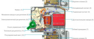
The PUE requirements also determine that when installing at the point where the PEN conductor is divided into the neutral protective and neutral working wires, it is necessary to provide separate clamps or busbars for the conductors connected to each other. The PEN conductor of the supply line must be connected to the terminal or GZSh (trip bus, Fig. 2) or the bus of the neutral protective conductor.
If there is no switching device or circuit breaker at the input, then using the release bus makes no sense, since it creates unnecessary bolted connections where contact may deteriorate.
Thus, it is necessary to have two busbars to separate the conductor. One bus will need to be used to connect neutral protective wires, the second - for zero working ones.
During installation, both busbars can be connected to each other using a cable jumper. The input combined PEN conductor is connected first to the PE bus, and then a jumper is taken from this bus to the N bus.
In accordance with the requirements of the PUE (clause 1.7.61), when using a TN system, it is necessary to re-ground the PE and PEN conductors at the entrance to the electrical installations of buildings, as well as in other accessible places, using primarily natural grounding conductors. The resistance of the re-grounding electrode is not standardized.
If there are no natural grounding conductors, then an artificial grounding is installed and connected to the PE bus, to which the PEN conductor is already connected.
For single-phase and three-phase input, the principle of separating the connected conductor is the same. The difference is that in a single-phase power supply system there is one input phase wire, and in a three-phase power supply system there are three phase wires.
In new apartments with a TN-CS grounding system, the division of the combined conductor into zero working and zero protective is carried out in the main switchboard. Two wires already go from it separately to the floor panel and to the apartments, as shown in the diagram below:
Finally, we recommend watching useful videos on the topic:
That's all I wanted to tell you about where the division of the PEN conductor into PE and N should be done according to the rules of the PUE. We will duplicate the answer once again so that you are sure to remember: in private houses the wire must be divided to the meter in front of the input switching device, and in apartments this is done in the main switchboard.
It will be useful to read:
Source
Neutral protective conductor
In systems TN-C, TN-S, TN-CS, where the neutral terminal of the transformer is solidly grounded, the neutral protective conductor connects the neutral point of the supply transformer and the conductive parts of electrical receivers, which may be energized in an emergency (indirect contact). The neutral protective conductor carries, as the name suggests, protective functions. The protective conductor is involved in the protection of both the electrical network itself and humans.
The neutral protective conductor is one of the types of protective conductors of the electrical network and it applies to electrical networks up to 1 kV with a solidly grounded neutral of the transformer or generator.
According to PUE 1.7.76. The following elements of the electrical network are subject to protection from indirect contact:
- Metal housings of lamps, electrical machines, transformers;
- Metal housings of distribution boards, apartment and floor panels;
- Metal housings of switchgears, trays, cable joints and metal structures with electrical equipment;
- Metal cases of portable and mobile devices.
As a protective measure, the connection of these devices to the solidly grounded neutral of the TP (power transformer) in TN systems or grounding in TT and IT systems is used.
In the diagrams, the neutral protective conductor is designated by two Latin letters “PE”. In normal operation of the electrical network, no electric current flows through the neutral protective conductor.
In the diagrams, the letters PE indicate not only the neutral protective conductor, but also all protective conductors of the network: grounding conductors, protective conductor in the potential equalization system, individual cores in cables, separately laid conductors and busbars.
Why divide PEN into two parts?
It makes sense to divide the PEN wire into PE and N cores only if each of them is intended to be used for its intended purpose. This can be done in the following cases:
- in a private (country) house, when a tap from the PE bus is made in the distribution board, used to organize local re-grounding;
- in a city apartment building, where the residents of the entrance agreed to install a common grounding loop on the street next to the entrance;
- a copper descent is carried out from the PE wire to a homemade ground loop.
To implement grounding with a homemade circuit, permission from the relevant energy services and approval from the housing and communal services will be required.
When in city houses a jumper is placed between the buses in the driveway panel, there is no need to talk about full grounding. The regulatory documentation on this matter provides a recommendation without a detailed explanation of the effect of such “grounding”.