Purpose, types of sleeves and crimping tools
To ensure contact between the connected conductors, special materials are used - sleeves. They are made from copper or aluminum tubes of various diameters according to the wires being fastened, so that electrochemical equality is maintained. Crimping is used in cases where it is necessary to withstand high current loads or when using other methods is problematic.
Table. Types of produced sleeves
| Name | Material | Description | |
| Copper | Aluminum | ||
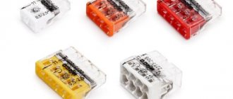
| GM | + | – | Without protective coating, looks like pipe scraps |
| GML | + | – | The surface is subjected to electrochemical sputtering (tinning). This protection protects the surface from corrosion and oxidation. |
| GA | – | + | For joining cables made of aluminum |
| GAM | + | + | They are used specifically for connecting cores of various materials. Made from two tubes by friction welding |
| GSI | + | – | Made from tinned copper tubes with external insulation. During crimping, the protective layer is not damaged and the assembly does not require any more additional manipulations |
To install wiring with a cross-section of up to 120 mm², you will need manual ones, and above that, hydraulic press pliers. The professional tool is equipped with dies and punches designed for different diameters. The size is adjusted by turning the matrix or punch. When working with aluminum conductors, quartz-vaseline paste is used to remove the oxide film from the metal surface.
Procedure for crimping wires
Crimping of wires is performed in a certain order:
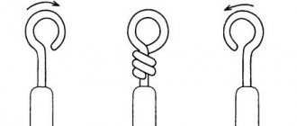
The end of the conductor is cut with a cutter as accurately as possible. In this case, the sleeve will be put on easily, without jamming the individual wires. The wire itself is marked to the required length and partially exposed along the length of the sleeve
All operations must be performed very carefully so as not to damage the wiring. If damaged, the contact will deteriorate significantly and the effect of such a connection will be significantly reduced.
It is forbidden to twist the wires before putting them on the sleeve, since the best crimping occurs when the wires are arranged in parallel, which increases their contact with each other. Twisted wires intersect, are pressed at the crimp points and become deformed. The sleeve is carefully placed on the exposed part of the conductor, and you can twist it a little. All that remains is to insert the sleeve into the appropriate clamp and crimp.
The use of sleeves is recommended in electrical equipment operating with high currents. In some cases, the cross-section of the wire does not allow the use of another type of connection. Sometimes there is simply no free space in the junction box, and the wires have to be connected outside of it. All these problems are easily solved by crimping with various types of sleeves.
Splices and crimping with sleeves
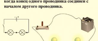
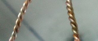
In electrical installations of any kind, bare “twisting” serves as a temporary connection of conductors at the testing and debugging stage. Such a connection cannot operate in a constant mode due to the mechanical action of the current and the elastic properties of the copper alloy. There is another reason: to maintain the nominal conductivity at the junction, the twist must be very long, because the contact area of two round wires is minimal.
Options for twisting or splicing wires. Mechanical connection of wires is a temporary solution
All these shortcomings are eliminated by crimping twists or individual cores using sleeves. In this case, the conductors are deformed and adjacent to each other with a significant area of contact, and the tightness of their pressing is ensured by an external belt that is not exposed to current.
In practice, it makes sense to connect wires with a cross-section of 10 mm2 or more by crimping; with less thick wires, it is more difficult to control the quality of crimping. As a tool for working with cables up to 35 mm2, it is better to choose manual lever crimpers, designed in the manner of bolt cutters: they are mobile, and in small sections, one muscle force is enough.
Crimping into a sleeve improves wire contact and mechanical strength of the connection
Large current-carrying lines (from 50 mm2), in addition to their massiveness, complicate the work with a high degree of responsibility. High-quality crimping is only possible with a hydraulic tool, of which there are two varieties. Lever jacks combined with a matrix in one housing are ideal for working on cable lines. It is especially convenient to work with such a tool at height.
When assembling panels and in cramped conditions, it is better to prefer separate crimping machines, in which the oil pump is pedal-driven and connected to the working part with a high-pressure hose.
It is extremely important to remember that reliable crimping is only possible with static force. Therefore, it is strictly forbidden to crimp tips and sleeves with a hammer (chisel).
Differences in wire crimping tubes by material
Connecting sleeves are divided into several types depending on the material of manufacture. The use of different types is due to the fact that, due to the electrochemical properties of metals, some react actively with each other, which leads to oxidation of the wires and their overheating under load.
Copper sleeves
The abbreviation GM indicates that the sleeve is made of high-quality copper. Used exclusively for connecting copper wiring. The surface of the GM is not covered with a protective shell, so it can only be used in non-aggressive environmental conditions.
Tinned sleeves
Tinned sleeves are used to connect copper wires intended for use in aggressive environments. These are the same copper sleeves, only their surface is coated with a special compound that forms a white protective shell. The abbreviation is as follows - GML.
The advantage of tinning is to protect the material from electrochemical corrosion, however, it is prohibited to use GML for aluminum wiring. This is due to the fact that during the compression process the protective layer is partially destroyed, which will result in direct contact between aluminum and copper.
Connecting tubes for cores made of different materials
The installation of electrical lines, as a rule, is not complete without the use and connection of cores made of different materials. For such purposes, special sleeves are used, which are considered combined and are called GAM. The design is simple, but its peculiarity lies in the use of different materials. Two parts of the tube are welded into one, one is made of aluminum and the other of copper. The middle, the junction is equipped with a special limiter. Thanks to it, equal input of the cores is ensured on both sides.
This variety differs in shape. This can be explained by the fact that the aluminum part of the tube has a larger diameter due to the need for a larger cross-section of the conductor.
The algorithm for crimping GAM is similar to the previous methods.
What is crimping wires with sleeves?
Crimping is a common procedure in electrical engineering; its peculiarity lies in the connection of electrical wiring with special sleeves. The connecting mechanism is a connecting tube made of metal. To crimp the wires, their cores are inserted into a sleeve. By crimping the tube with the wires inside, it is possible to achieve a reliable connection. At home, crimping is done using pliers, but it is preferable to use a special tool - press pliers.
The sleeve is compressed in two or three places, and the pressed area is insulated using insulating PVC tape or heat shrink tubing. Sometimes insulated connecting sleeves are used to connect elements; in this case, there is no need to re-process the electrical wiring section.
Connecting wires with sleeves must be carried out in the following cases:
- It is necessary to connect wires with a large cross-sectional area.
- There is no possibility of using alternative methods of connecting the wire. For example, wiring inside a distribution box where visibility is poor at high altitudes or where it is impossible to place the terminal block.
- It is necessary to connect wires in lines with high load.
Crimping sleeves for wires have their advantages and disadvantages. The first ones predominate:
The crimping tool is equipped with a comfortable working area. This principle of operation allows you to perform assigned tasks in a limited space, for example, in distribution boxes or a socket box. Inside the socket box, crimping the wiring contacts allows you to shorten the wires to an absolute minimum. To compress the tube used, crimping pliers are used. Unlike analogues, this tool does not require a connection to electricity to operate and belongs to the group of manual ones. If the power is not yet connected, crimping is the only reliable way to connect the wires. To carry out soldering or welding, you must have certain knowledge and skills. Any person can cope with crimping after the first trial time
It is important to have press pliers and consumables; in extreme cases, you must have pliers.
The disadvantages include the following:
- The need to constantly have in stock and regularly replenish stocks of cartridges of different sizes.
- The connection is characterized by considerable dimensions, which sometimes complicates the implementation of certain tasks.
It is also worth mentioning the significant costs of consumables.
Methods for connecting conductors in a box
There is no single possible method. When choosing a way to connect wires in a junction box, an electrician weighs all factors: from the cost of materials to the expected load.
- Terminals. There is an opinion that this method is the most reliable, but this is a false statement. Most often, terminals are used on boxes with ready-made contact pads.
This connection of wires in the box allows you to disconnect one of the lines at any time (for example, for repairs) without causing damage to the entire power system. There are two ways to connect, directly to the block (by making a ring from a wire core), or using a terminal. With the ring everything is simple, you just need to ensure that the wire is laid in such a way that when tightening the threaded connection, the contact does not loosen.
But with terminals everything is more complicated. It is irrational to crimp a single-core wire: you can mechanically damage the conductor, and the core will break off at any moment. And when laid in a box, a single-core cable with terminals takes up a lot of space, and it is difficult to separate different phases at a sufficient distance.
An excellent result is obtained when crimping a multi-core soft cable; the contact terminal fits comfortably. But stationary installation of multi-core cable is nonsense.
Bottom line: Terminal blocks in the distribution box are convenient, but it is better to make the connection directly to the conductor under the screw, without using crimp terminals.
There are modern boxes with quick-installation contact blocks. This solution is really convenient, but is designed for light load.
Thus, the use of contact blocks is justified only if it is necessary to periodically disconnect one of the lines. And even then, sooner or later the conductor will break off.
- For standard wiring in an apartment (or household), the classics are still more suitable:
Welding wires in a junction box has been used since time immemorial. Anyone who repaired their Khrushchev or Brezhnev cars probably noticed a drop of solidified melt at the end of the aluminum strands in the boxes.
Today, the use of aluminum wiring is prohibited by the PUE, and the welding connection method is still popular. The point is this: after carefully twisting the stripped wires, the contact of the welding machine is briefly applied to the end point.
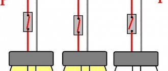
Usually this is a compact device of low power. It is used by almost all professional electricians. Works on the principle of a spot welding spotter. It will not be possible to light an arc, but the metal at the point of application melts properly. The figure shows the simplest circuit that can be assembled at home.
The connection quality is more than sufficient. In addition to the total twist length (40–50 mm), the ball at the end forms a point with minimal resistance. An additional plus is that this twist will not unwind even when moving the wires inside the box.
If a welding machine is not available, we limit ourselves to ordinary twisting. Of course, we make the connection not with our fingers, but with the help of pliers. All ends of the conductor must be stripped (but not reduced in cross-section), the length of the bare part before twisting begins is at least 70 mm.
Twisting is done after the wires are finally secured in the box. If the cable moves, the connection may become weak. The result is sparking, overheating, and contact breakage. It will be good if there is no fire.
- As an option, after twisting, the wires are soldered in the junction box.
Important! There is a widespread opinion among amateurs: under load, the twist will heat up and the solder will melt. Firstly: a load capable of heating a conductor to the melting temperature of solder is unrealistic at home. Of course, provided that the circuit breakers are in working order. Secondly: heating during twisting occurs due to loose contact, and this can be solved by soldering.
The reliability is not much worse than with welding. In this case, there is no need to purchase (do it yourself) a welding machine, a fairly powerful soldering iron, or even a hair dryer.
Tip: Use the most powerful soldering tool possible. It is better to expose the contacts to high temperatures for a short time than to heat the contacts slowly and for a long time with a weak heater.
During heating, monitor the condition of the insulation. If it starts to melt, take a break until it cools completely. Immediately after soldering, do not move the wire; allow both the solder and the insulation to cool.
Use refractory solders; these alloys have higher strength characteristics.
- Crimping. From the point of view of electrical conductivity, the quality of contact is no better than that of conventional twisting. But the strength of the connection increases significantly. If it is not possible to weld or solder the twist, crimp it using a special sleeve.
You can get by with pliers, but a special tool is still more reliable. There are bushings for parallel splicing of wires, and there are for fixing twists. There is no fundamental difference. If there are two or three conductors, parallel crimping is suitable. For larger quantities - crimping after twisting.
In fact, the methods discussed above are a modernization of the good old twisting. You should not be skeptical about the issue. Due to poor contact in the junction box, many fires occurred and damage to household appliances was caused. Therefore, when repairing electrical wiring in your home, use technical means to improve contact in the twist to the maximum.
Manual press pliers - how crimping occurs
When connecting wires using the crimping method, the electrical contact that is created between them is rightfully considered one of the most reliable. Manual press pliers for crimping PK-16 sleeves, produced by the KVT company, are a compact crimping tool that allows you to perform this work efficiently.
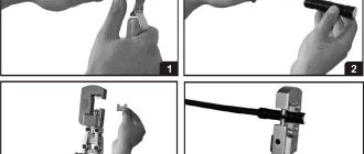
To perform crimping you must do the following:
- - strip the insulation from the wires that need to be connected;
- — the stripped wires are threaded into a sleeve, the diameter of which is equal to the sum of their sections (the sleeve must be made of the appropriate metal);
- — crimp using the above tool;
- — insulate the sleeve with electrical tape or heat-shrink tubing.
At first glance, the procedure is quite simple, but it is the use of the correct press tongs that is the most important nuance. Therefore, the choice of such a tool must be balanced and deliberate. After all, not everyone can squeeze ordinary hand press pliers with a force sufficient for high-quality crimping.
The model of manual press tongs that we will consider in this article are excellent for solving the problems described above. These are hand press pliers PK-16 from.
Connecting wires by soldering
If the twisted wires are soldered , we get a connection of wires by soldering , which guarantees reliable and high-quality contact, which has a fairly low contact resistance, high conductivity and mechanical strength. But it is important to solder the wire connection correctly; for this you need:
- tin the connected wires with rosin (flux);
- the solder should flow into the twist;
- After the solder has cooled, you can sand it with sandpaper, because sharp edges of the solder can pierce the insulation;
- insulate the wire connection.
But such connection of wires by soldering is very labor-intensive and requires certain skills. The negative aspects of soldering wire connections, I would include:
- need for isolation;
- complexity (not everyone knows how to solder well), and even for those who are good at soldering, doing this, for example, while standing on a stepladder or ladder, to put it mildly, is not very convenient;
- if a mistake was made when connecting the wires, it will not be easy to separate them after soldering, so it is better to leave a larger supply of wires and cables;
- high time consumption.
Connection Features
The technology involves two options for crimping. This is a method of local indentation and continuous compression. Copper or aluminum wires are used for work. The sleeve must also be made of these materials. There are also elements made of copper-aluminum alloy.
Since aluminum cables are prone to the appearance of oxidative films on them, the sleeve must first be cleaned and treated with special lubricants. Copper wires are also pre-treated. The use of lubricants in the process reduces the risk of possible damage to the cores. The friction force is also noticeably reduced. Pressure testing is carried out using manual or hydraulic tools. In the latter case - with a figure press. It is usually used in large industries.
How it works? The two ends of the cable are crimped until they take a round shape. Next, the core is inserted into the sleeve until it stops. It is possible to connect not exactly end-to-end. But in this case, the cross-section of all cores does not exceed the bushing. In the case of local compression, contact directly depends on the depth of the pits. The latter can be measured with a caliper. If continuous compression is used, then check the cross-sectional area. Then, when the crimping of the wires is completed successfully, it is necessary to treat the outer layer with electrical tape or elbow cloth. Next, the wire and cable are carefully laid in the junction box.
Connecting wires by twisting
Connecting wires by twisting is common everywhere, but if we turn to the main book of electricians PUE, then according to:
As we can see, there is no twisted connection of wires at this point, which means twisting of wires is prohibited. But twists have always been, are and will be used to connect wires when installing electrical wiring. Yes, and well-made twisting can last for decades, but the connection of wires by twisting must be done efficiently. The technology for connecting wires and cables by twisting is quite simple:
- the length of the twist must be at least 4-5 cm;
- The connected wires, stripped of insulation, must be cleaned of the oxidized film, for example, with an ordinary knife or sandpaper;
- It is necessary that the connected wires wrap around each other evenly and tightly, ensuring sufficiently reliable contact.
One “but”, problems may arise when handing over the electrical installation to the fire inspectorate, because... Connecting wires by twisting according to the PUE is prohibited. However, this applies mainly to industrial consumers, retail premises, etc.; a fire inspector will not come to your apartment or private house to inspect it.
Connecting wires by twisting is a necessary measure when there is nothing else left, and it is better to use connection of wires using the methods described below.
Features of using NShVI tips
Electrolytic copper is used to make pin sleeve lugs. There is insulation on the back of the product. To prevent corrosion from damaging the metal, copper is treated using galvanic tinning. The size of these tips varies between 0.25-150 mm.
When crimping NShVI, time is significantly saved, which simplifies the process of connecting electrical devices. The tips are suitable for household use. They are designed for crimping multi-core wires of any type. Manufacturers produce two types of NShVI. Some lugs are used for crimping one wire, while others are designed for two.
Products are marked as follows:
- Single - the first digit of the marking indicates the section size, and the second displays the length of the contact part.
- Double - the number “2” in brackets indicates that this tip is intended for splicing two wires, and the next number means what the cross-sectional size of each of them is.
The sizes of NSHVI crimp lugs range from 0.25 to 150 mm
It is desirable that the size of the shank in the tip be slightly larger than the cross-section of the wire, i.e., its bare wires. So, for a 1.25 mm cable, you should purchase an NShVI with a cross section of 1.5 mm.
Basic rules for crimping wires with sleeve-type lugs
You can connect wires efficiently using a lug at home, without professional skills and knowledge. To do this you need to adhere to the basic rules:
- Select the correct type and size of wire lug for crimping.
- Clean the conductors thoroughly and correctly.
- Use only specialized tools for work.
- Follow the crimping technology exactly.
Typically, the insulation on the wire is removed taking into account the size of the contact part of the tip. After stripping, the end of the core should coincide with the edge of the sleeve. To achieve this, you need to add 2-3 mm to the length of the cleaned area
It is very important to choose the correct tip size. In order not to make a mistake, you need to be guided by the color markings in which the insulating cuffs are painted
To crimp wires with ferrules, you must use only special tools
There are some subtleties when working with insulated connectors. It is imperative to ensure that the insulating material on the wire goes all the way inside the cuff and is completely covered by it.
Preparatory work is carried out in the following order:
- The veins are cut strictly perpendicularly.
- To remove the insulating layer from the cores, it is necessary to take into account the size of the shank and the increase.
- If the conductors are copper, the oxide film must be removed from their surface. To do this, the exposed area is degreased and then lubricated with technical grade Vaseline.
- If the shape of the cores is sectoral, you will have to round them.
- If the wire cores are made of aluminum, this metal must be cleaned to a shine. After this, the bare area is treated with quartz-vaseline lubricant, which will prevent the appearance of an oxide film.
Soldering wires
Tinning and soldering of cables in the distribution box is carried out in several stages.
- Removing the insulating layer.
- Stripping the wires until the characteristic shine of the metal appears.
- Maintenance.
- Twisting.
- Soldering.
- Isolation.
Before you start connecting the current-carrying wires, you need to analyze what length is required. The wires are cut so that when soldering the ends are located outside the junction box. Upon completion of the work, they are laid in any desired way.
Soldering wires in the junction box is prohibited. The stock in this case is also inappropriate.
To remove the insulating layer, a special tool is used - a stripper or a sharp knife. When working with a sharp knife, the movements should resemble whittling a pencil. It is forbidden to cut the insulating layer with pliers or side cutters; you cannot make circular cuts. Transverse damage will cause a break in the near future.
Bolted connection of cables and wires using a special clamp (“nut”)
In my practice, there have been cases when it is necessary to connect wires made of different materials (copper and aluminum). Here you simply cannot do without a bolt with a nut and a washer, with the help of which current flows through the conductor without any problems. The main thing here is to thoroughly tighten the bolted connection with a wrench for better contact. However, this must be done without fanaticism, otherwise you can ruin the whole thing in the bud by breaking a key or bolt.
Also, in this case, the so-called “walnut” can be very useful, but not a walnut, but a metal one. This is a clamp that also needs to be pulled through, only with a screwdriver, having previously inserted the exposed wires into special grooves.
Termination of wires and cables by soldering
You also need to remember that if you don’t have the necessary press or tips on hand for terminating a stranded copper cable, then the good old grandfather’s method of tinning cores will come to your aid. You will need a soldering iron, solder, rosin, and of course a 220 V connection point (in common parlance there is a socket, and you are unlikely to find a 380 V soldering iron).
So, armed with this tool, you need to strip the core, depending on the place to which the core will be connected (motor, cable twist or circuit breaker), to different lengths.
For example, when connecting a motor, you need to make a “ring” and accordingly strip the wires depending on the size of the terminal block (which in turn depends on the power of the connected electrical appliance by 20-30 mm. When connecting several wires and then twisting, it is better to strip them by 25-35 mm depending on the cross-section of the core. When connecting the machine, a straight section of 10-15 mm. To strip the cores of insulation, I advise you to use a tool like KSI (insulation stripping pliers) or as it is now also called a stripper.
When twisting cores, it is not necessary to use soldering, since today there are spring clamps of the PSI type (connecting insulated clamp) and they allow wiring to be carried out most quickly and no less efficiently than when using soldering. With PPE, you won't have to use tape or heat shrink tubing to insulate your twists.
For example, if you take a cable with aluminum cores and connect an electric heater, then after some time the cable insulation will melt and the core will turn into something similar to old porcelain that will crack at any moment. This will happen due to the fact that the connection does not provide reliable electrical contact and does not have mechanical strength. And when crimping, welding, or soldering the ends of wires or cables using the technology described above, issues related to termination will not arise and a fire can be avoided.
To summarize, I want to say that if you are going to make repairs and change electrical wiring, then use a copper cable with single-wire conductors. If you need to connect the engine of an overhead crane or excavator, use flexible cables and crimp them with appropriate lugs. Tools such as press pliers and insulation stripping pliers will help expose the conductors and prepare them for crimping.
When the core dimensions are more than 16mm2, use appropriate hydraulic press dies. If you do not trust the manufacturer of the cable or lugs, then be sure to make a cut with a file or needle file to make sure that it is really a copper cable or lug, and also do not forget that high-quality lugs are necessarily coated with a special layer of tin, which protects the core material from oxidation.
Such tips will serve you longer and, accordingly, you will be confident in reliable connection contact. High-quality tips are made in accordance with GOST, less reliable products for terminating are manufactured in accordance with specifications.
And in conclusion, by using an appropriate tool that has a manufacturer’s certificate, and not pliers and a knife, as unqualified “specialists” do, you increase the chance of doing your job efficiently, reliably and quickly.
How to connect wires by crimping in a junction box
In distribution boxes, the most common task is to route a 2.5 mm2 line into several directions. If copper wires are used, then the connection requires sleeves for crimping copper wires and special press pliers.
Let's look at how to crimp wires with sleeves in a distribution box; for example, let's branch the cable in the distribution box in three directions.
First, the insulation from the wires is cleared to a length corresponding to the length of the sleeve. The stripped ends of the wire are inserted into the sleeve very tightly so that there are no voids.
If they. However, it turned out that often when connecting three or more wires, it is necessary to “stuff” them with pieces of cores of the same wire, the length corresponding to the length of the sleeve.
I would like to draw your attention to one very important point. If you compress several conductors into one sleeve, with a standard cross-section of wires and sleeves it will not be possible to pack the sleeve tightly; there are always voids left in it and these voids must be filled
To do this, you need to “finish off” the sleeve with several more pieces of the same wire. This will allow you to create high-quality and reliable contact at the crimping site.
Crimping of wires is carried out using two or three presses in different directions (to do this, the press pliers just need to be turned 180 degrees).
It is especially important to remember that the wires must not be twisted before connecting with a sleeve. For the specified brand of wire, when connecting four branches, another sealing piece of wire and a sleeve with a cross-section of 2.5 mm2 are required
When the sleeves are put on and tightly finished off with pieces of wire, you can begin crimping. For this I use hand press pliers PK-16.
In order for the sleeve to be securely pressed, we do two presses along the edges of the sleeve (at the beginning and at the base). We do presses in opposite directions.
Crimping of wires is performed using GLM-10 sleeves. During operation, the working area of the pliers must correspond to the size of the sleeve.
The photo clearly shows that the sleeve is compressed with two opposite presses. This allows you to improve the quality of contact at the junction.
The ends of the wires extending outward are cut with pliers to fit the edge of the sleeve.
The entire connection is insulated with a heat-shrinkable tube, the length of which is selected so that it extends 1 cm beyond the outer cut of the sleeve and extends onto the insulation by 1.5 cm. If you don't have heat shrink tubing, you can use electrical tape.
We heat the heat-shrinkable tube placed on the sleeves using a hairdryer. After compressing the tube, the connection points are reliably insulated.
After insulation, carefully lay the wires in the junction box and close the lid. All our wiring connections are done.
Connecting wires with PPE caps
Connecting wires with PPE caps (Connection Insulating Clamps). PPE are plastic caps with a conical spring inside, which, when twisted, compresses and fixes the wires, and the plastic PPE cap itself insulates the connection of the wires and is fire and mechanical protection.
This wire connection is quick and simple; to perform it correctly you need:
- strip the insulation from wires and cables to a length slightly shorter than the length of the PPE cap itself;
- fold them into a bundle, precisely into a bundle, and not twist them;
- use your hands to twist the PPE clockwise onto the bundle of wires;
- tighten the PPE using pliers.
The advantages of such a connection of wires and cables are obvious (no special tools required, no need for additional insulation, speed and simplicity), but there are also disadvantages:
- Do not connect multi-wire wires;
- the quality of such a connection will be worse than those listed above, so I would recommend using these clamps for small loads, for example, in lighting circuits.
PPE caps are divided according to the total cross-section of the wires to be twisted and are designated by numbers from 1 to 5, which indicate the number of wires to be twisted and their cross-section.
The essence of the method and advantages
Most experts recommend using crimping as the main and only method of connecting wires.
Wire crimping is a method of connecting them using special sleeves. Visually they resemble ordinary tubes. The main task is to play the role of a connecting mechanism.
The wire strands that need to be connected are inserted all the way on both sides of the sleeve and crimped with special press pliers. The result is a reliable and durable electrical assembly. The tube needs to be compressed in several places, depending on the cross-section of the switched conductors and the length of the cores. The connected sleeve with the conductors is also subject to deformation. Due to compression, the conductors adhere, which ensures reliable electrical contact. Finally, you must insulate the connection point.
Sleeves for crimping wires
The crimping method is most in demand in the following cases:
- if necessary, connect wires with a large cross-sectional area;
- for connecting multi-core conductors;
- if there is a need to connect wires in power lines with a high current load.
- The tool designed for crimping sleeves is used without electricity. In rooms where there is no voltage, crimping is the only connection method.
- Such a connection does not require maintenance throughout its entire operational life.
- Using sleeves, you can connect conductors made of different metals. One of the most common problems faced by electrical installers is connecting copper and aluminum conductors.
- The quality of the connection is at a high level, the amount of time spent is minimal.
- A special crimping tool allows you to connect wires even in very limited spaces, for example, in a box or electrical outlet.
Crimping with sleeves
Connecting conductor cores with sleeves
The method consists of putting a metal tube (sleeve) on the cores freed from insulation, which is crimped with press pliers. As a result, the conductors are tightly connected to each other. The connection point is isolated.
Important: connections of aluminum and copper conductors may only be made using sleeves specially designed for this purpose.
Types of sleeves
It is very important to choose the right sleeves for crimping wires
According to the material of execution
A copper cable or wire should be crimped with copper sleeves accordingly. They come in two types and have the following abbreviation:
- GM - copper sleeves. They are made purely of copper, do not have any coating or processing, and in appearance they look like ordinary pieces of copper pipes.
- GML – tinned copper sleeves. They undergo a tinning procedure, that is, their surface is treated with a special tin-bismuth layer. This is done in order to prevent oxidation and corrosion processes. It is also known from school physics lessons that copper, like any other metal, oxidizes. Tinning prevents this process; the crimped wires will not enter into a chemical reaction with the tinned sleeve.
I would like to give one useful piece of advice. Do not listen if suddenly one of the experienced electricians tries to prove to you that using GML sleeves it is possible to crimp aluminum wires, since the tin layer will not allow direct contact of aluminum with copper. This is incorrect, because during crimping the surface layer of the tube is deformed and the corrosion process is still inevitable.
To connect aluminum wires, they use products made of the same metal; they are designated GA (aluminum sleeve).
There are also combined sleeves, they are designated GAM (aluminum-copper sleeve), in everyday life many call them aluminum-copper. This option is used when you need to connect wires made of different metals end to end. The sleeve is a tube of two parts; at the junction of dissimilar metals, the connection is made by friction welding. Here everything is extremely simple and clear - you need to insert copper wires into the part of the tube made of copper, and an aluminum conductor into the aluminum part.
And the most modern version with the designation GSI (insulated connecting sleeves). They are based on ordinary tinned tubes, only they are covered with polyvinyl chloride insulation on top. They crimp copper wires. During crimping, the insulating layer is not removed, pliers are put on top of it, and compression is performed. Such sleeves greatly simplify the work of an electrician, since the crimped electrical assembly no longer requires any additional measures to insulate it.
By size
After the letter designations, a number is written on the sleeve. What does it mean? This is the cross-section of the conductor for which this product is designed. For example, tinned copper sleeves are produced for wires with a cross-section from 2.5 to 300 mm 2. Accordingly, with an increase in the cross-section of the conductor, the sleeve itself has larger dimensions (diameter and length). For combined products, two numbers are written through the fraction, one indicates the cross-section of the copper conductor, the second - the aluminum.
By design
The sleeves also differ in design. They can be hollow, that is, inside they are bare through tubes. And they come with a partition in the middle, which allows you to adjust the depth of the conductors, that is, the tips of both connected wires will enter the sleeve to the same length. Combined sleeves are produced with partitions, which are used when connecting conductors at the joint.
Features of crimping large diameter wires
For high-quality crimping of contacts with a line cross-section of more than 6 sq./mm, human muscle strength is no longer enough to do this with an ordinary hand tool. Strippers for removing insulation and classic press pliers and crimpers do not even provide holes of a larger diameter. The insulation is removed with a regular assembly knife, and for the press, reinforced pliers with long handles or a hydraulic press are used.
This tool is ideally adapted for crimping tips and sleeves of domestic standards. There are various modifications of hydraulic pliers for crimping electrical line connections, with a pressure force from 8 to 55 tones per sq./cm; the set includes replaceable dies of various diameters. One of the popular types of this tool is PRG-70V, its main characteristics:
- Pressure force – 8 tons;
- Hexagonal crimp shape;
- Hydraulic piston stroke 100 mm;
- Set of replaceable matrices for wires 4;6; 8;10;16;25;35;50;70 sq/mm.
Working with a hydraulic press
Cleaning the insulation and installing the bare ends into the sleeves is carried out in the same sequence as described above. The matrix of the required size is installed in the press rod, the valve that blocks the circulation of hydraulic fluid is set to the “Closed” position. The structure to be crimped is placed in the hole of the matrix, pressing is performed by swinging the handle until the component parts of the matrix are connected.
The valve opens a quarter turn, the pressure on the rod with the matrix is removed, we advance the sleeve to compress the next section, and repeat the operation along the entire length. In the last section, open the valve and remove the matrix with the pressed sleeve.
The advantage of this connection technology is the high contact strength and reliable electrical connection, the ability to connect lines made of different metals. The disadvantage is that the connection is not removable, the wires can only be bitten off. Hydraulic presses are produced in various capacities, the largest is capable of compressing a cross-section of 1000 sq./mm. This equipment is rarely in demand at home; it is intended for professionals. It is not advisable to buy it to perform one-time work; if necessary, it is better to negotiate a lease with the owner.
![Turboloan [CPS] RU March](https://dush-pol.ru/wp-content/uploads/turbozajm-cps-ru-mart-330x140.jpg)