What is the best way to connect light bulbs in series or parallel?
When placing network lighting devices (lamps or LED strips), as a rule, there is no doubt about how to connect them to each other. If they are designed for a voltage of 220 Volts, the traditionally used connection method is a parallel connection. Serial connection of light bulbs is used only in rare cases, when garlands are made based on them, for example. Another common reason for using this method is the desire to increase the life of lighting products by using them at partial operating power.
Serial connection
A non-standard serial connection of light bulbs to a 220 Volt network has the following characteristics:
When connecting light bulbs in series in a circuit with a common switch, lights designed for 220 Volts will not burn at full power.
When two incandescent light bulbs with different power P are installed in a chain, the one with higher resistance, that is, less energy-intensive, burns brighter. This can be explained very simply: due to the greater internal resistance, the voltage across it will be more significant in magnitude. Since this parameter is included in the formula for P in the square P=U2/R, then with a fixed resistance, more power is dissipated on it (it burns brighter).
The advantage of sequential switching of lamps is a more gentle operating mode due to the lower power consumed by each of them. In all other respects, this method of connection is undesirable, since it has the following characteristic disadvantages:
The sequential option is optimal for creating “soft light” in sconce lamps or when making garlands from low-voltage LED elements.
Better to connect in parallel
When there is a parallel connection of lamps, the power supply voltage always appears at the terminals of each of them. Between them there can only be conductors of electric current. Their resistance is neglected due to its extremely small value. The parallel connection scheme eliminates mutual electrical interference between light sources. Each of them shines at full power if connected to the output of a power source with a voltage corresponding to their nominal value.
- It is recommended to connect incandescent lamps and LEDs in series only if necessary to connect the simplest and cheapest power source for low-voltage light sources - a 220-volt electrical network. Everyone has encountered light sources connected according to this scheme. This is a Christmas tree garland.
- The connection of incandescent lamps, as well as the connection of lamps, is generally recommended to be done in parallel. This connection diagram will not leave you completely without light if even a few light bulbs burn out.
Parallel connection
The classic parallel connection of lamps differs from the serial method in that in this case the full mains voltage is applied to all illuminators.
When connecting light bulbs in parallel, each branch has its own current flowing through it, depending on the resistance of the given chain.
The conductors supplied to lamp bases and sockets are connected to one wire in the form of a parallel assembly. The indisputable advantages of this method include the following features:
Parallel connection
In circuits connected in parallel, the full voltage of the power source is applied to each element. In this case, the current flowing through each of the branches depends only on its resistance. The wires from each cartridge are connected to each other at both ends.
- if one lamp burns out, the others will continue to perform their functions;
- each of the circuits shines at full heat regardless of its power, because full voltage is applied to each;
- you can remove three, four or more wires from the lamp (zero and the required number of phases to the switch) and turn on the required number of lamps or group;
- Energy-saving light bulbs work.
To turn on the lights in groups, assemble such a circuit either in the lamp body or in the junction box.
Each of the lamps is turned on by its own switch, in this case there are three of them, and two are turned on.
Laws of mixed compounds
The mixed inclusion of illuminators is described as follows:
It is possible to connect various types of consumers to separate parallel branches, including incandescent lamps, as well as halogen or LED sources.
When considering the characteristics of a mixed compound, the following patterns must be taken into account:
It is recommended, when using a mixed circuit, to group lamps of the same power into serial circuits, and to place illuminators with different energy consumption in parallel branches.
Types of lamps and connection diagrams
Before installing various types of lighting devices, it is advisable to familiarize yourself with the operating principle and their internal structure, as well as the features of the connection circuit to the power supply network. It is also important to know that each of the varieties is capable of working for a long time only if the operating rules are strictly observed.
Fluorescent lamps
In addition to traditional incandescent lamps, their fluorescent tubular analogues are often used to illuminate office and partially domestic spaces. They are most often installed at the following facilities:
What is parallel connection?
In electrical engineering, parallel connection should be understood as a method of connecting electrical devices in which each of them has a similar connection of poles in relation to the power source or in the electrical circuit.
To do this, consider an example of parallel connection of incandescent light bulbs:
Rice. 1. Parallel connection of lamps to the source
As you can see, here each lamp from L1 to L4 is connected with one contact to the phase terminal, and the second to the zero one. Or in the same order for a DC circuit - one lamp contact to positive, and the second to negative. Thus, it turns out that all phase terminals are the same and connected to one point, and the zero terminals are also connected to one point. From the technical side, parallel connection can be made with any number of lamps from two or more.
Serial and parallel connection of light bulbs
Incandescent lamps are a very common light source. In chandeliers and other lamps, as well as in suspended and suspended ceilings, there can be three, five, or even several dozen. Each such light source is one of the elements of an electrical circuit, which, as we know from the school curriculum, can be connected in different ways both to each other and to other elements in the circuits. Let us further remind our readers:
- in which diagrams are the lamps connected in parallel?
- on some - sequentially;
- and what is the essence of the various lamp connections.
Having seen how the lamps are connected to each other in the diagrams, our readers will subsequently be able to make the optimal choice of lighting system.
Chandelier with many bulbs
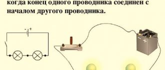
Electrical circuit with serial connection
Elements of electrical circuits can be connected either in series or in parallel. The series connection and parallel connection of lamps are done in the same way. These are completely different compounds that lead to different results from their work. To clearly understand the details of these connections, consider the example of incandescent lamps. We take two light bulbs, two sockets and connect wires to their terminals.
In order to clearly distinguish the conductors when connecting, we choose red and black colors for them. For incandescent lamps, which are essentially resistors, these wires will be, as it were, equal. Changing their places will not affect the operation of the lamp in any way.
Let's make a series connection of light bulbs:
- we place them on the table with the wires straightened, with the ends stripped of insulation;
- randomly select one wire in each lamp. For clarity, let's select both black wires;
- twist the ends of the two selected wires.
If the free ends of the two red wires are connected to a power source, electric current will flow through the bulbs. It will be the same in each lamp. Moreover, no matter what the characteristics of this lamp are. In order to determine the power of an incandescent lamp, you will need to know both the current value and the voltage value. As a result of the series connection, each lamp influences the operation of the other lamps.
A lamp, like any resistor in an electrical circuit, produces a voltage drop. Its value is determined by Ohm's law for a section of a circuit as the product of current and voltage values. When the filament is heated, which corresponds to the correct mode of operation of the light bulb, its resistance is such that the energy released, including light, ensures its optimal brightness and duration of operation. Therefore, each light bulb can only work effectively at a certain voltage. And the resistance of the hot luminous spiral will correspond to it.
The weaker the brighter
When two light bulbs are connected in series, the voltages across them will be the same only if the resistances of their spirals are the same. And this will only work if they have the same design. For this reason, before connecting series-connected lamps to a power source, it is imperative to know their operating voltages (or currents) and power. If these characteristics are not present, it is difficult to correctly assess by eye the optimal brightness for a light bulb.
Physical parameters
An important step when connecting halogen, LED or fluorescent lamps is physical data. The main parameter for all lamps can be considered ohmic resistance, on the basis of which power consumption is calculated.
For example, consider the option of connecting lighting devices as a classic resistive load:
Rice. 3. Parallel connection of resistive load
So the same filaments represent a purely resistive load, so we will calculate them as the sum of resistors R1 - R3. For parallel circuits, the total resistance of all devices is calculated based on the ratio:
After transformation, the expression will look like:
A similar calculation is made for the inclusion of fluorescent and LED lamps. Note that in calculations under ideal conditions the resistance of the connecting wires is neglected. This technique is also relevant for most lighting devices, since the value is disproportionately smaller. However, in the case of calculating low-current lamps or LEDs, the resistance of the wires cannot always be neglected, so they are also included in the calculations.
Advantages and disadvantages
For home and industrial purposes, parallel connections are widely used to solve various problems. When choosing this method, it is important to consider the pros and cons, so next we will look at the advantages and disadvantages for lighting with fluorescent, incandescent, LED or other types of lamps.
The advantages of the scheme include:
The disadvantages of this connection method are mostly related to economic aspects or emergency operation modes:
Rules for parallel and series connection of lamps
In everyday life, parallel connections of light bulbs are most often used, but sometimes a series connection is more profitable.
Due to the growing popularity of spotlights, there are more lighting fixtures in apartments and private homes.
If you need to replace a light bulb, there are no problems; adding additional light sources is more difficult.
If such work is carried out independently, the ability to determine the advantages of each type of connection and draw up diagrams is required.
Practical use
All connections in electrical circuits are divided into serial and parallel. In practice, a parallel circuit is used for any lighting in your home:
- spotlights;
- lamps in a chandelier;
- modules in LED strip, etc.
Regardless of the specific type of connection and equipment used, the diagram will be identical. In some situations, a power supply or electronic transformer is used to connect spotlights; in others, fluorescent lamps are installed directly from the network, as shown in the figure below:
Rice. 4. Connecting lamps by room
Features and characteristics of lamp connection diagrams
The method and order of connecting the lamp depends on its type. The methods used for incandescent light bulbs will not work with halogens, fluorescent lights, or LEDs.
Parallel
When using a parallel connection circuit, light sources are connected to phase and neutral. For example, if you need to connect 2 light bulbs, their power wires are twisted. It is important that the cross-section matches the load. The voltage on all lamps is the same, they burn with the brightness set by the manufacturer. Burnout of a single element does not affect the functionality of the others.
Reference! In practice, when there are several light sources, the wires are not twisted when connected in parallel. A cable is used to which all elements are connected.
Parallel connection can be:
When using a parallel beam model, the burnout of one element does not interfere with the operation of the others. Before choosing a daisy chain model, it is necessary to take into account that disruption of one connection will damage the elements located after it. But the problem is solved quickly due to easy identification of the problem area.
When connecting halogen sources to a transformer, it is necessary to take into account that they are connected to the secondary winding of the converter through terminal blocks.
The main disadvantage of fluorescent lamps is flicker. Ballast control equipment eliminates this problem, but it is expensive. To reduce ripple, a special circuit is used for two lamps with a phase shift on one of them. Two light bulbs are connected in parallel, a phase-shifting capacitor is connected to one.
Parallel connection rules, diagram
All devices that are connected in parallel or in series operate according to their own rules. They are based on the basic laws of electrical engineering and some subtleties.
Sometimes these subtleties are not obvious to those who know little about the topic. When working with one or another connection scheme, you need to consider:
- a series connection is characterized by the same current indicators in all sections;
- in each specific type of connection, Ohm's law takes on its own meaning - in a series connection, the voltage corresponds to the voltage on all parts of the circuit;
- with a parallel connection, the voltage of individual sections of the circuit does not add up - it is the same everywhere;
- The current strength in a parallel type connection corresponds to the total current strength of all branches of the circuit.
Consistent
To connect two lamps in series with wires, 2 of them are twisted, the rest are connected to phase and neutral. When connected to voltage, current flows through one filament, then hits the other and meets zero. The current does not change, the voltage decreases (divided in half if there are two lamps). When three light sources are connected in this way, the voltage on each will be approximately 70 V, and they will glow only a little.
Source
Which light bulb will shine brighter and why?
A lamp whose filament has greater resistance will burn better and brighter.
Take for example light bulbs that are radically different in power - 25W and 200W - and connect them in series.
Which one will glow at almost full intensity? The one with P=25W.
The resistivity of its tungsten filament is significantly greater than that of two hundred, and therefore the voltage drop across it is comparable to the voltage in the network. With a series connection, the current will be the same in any part of the circuit.
At the same time, the amount of current that can ignite 25 watts is in no way capable of “setting fire” to two hundred. Roughly speaking, a light source with a lamp of 200W or more will be perceived relative to 25W as an ordinary section of wire through which current flows.
You can increase the number of lamps and add one more to the circuit. This is done again very simply.
Twist the two ends of the power wire of the third lamp with any ends from the first two. And to the remaining ones you again supply 220V.
1 of 2
How will this garland glow in this case? The voltage drop will be even greater, which means the light bulbs will not only light up at half power, but will barely burn at all.

