December 23, 2013
Switching power supplies, thyristor regulators, switches, powerful radio transmitters, electric motors, substations, any electrical discharges near power lines (lightning, welding machines, etc.) generate narrowband and broadband interference of various natures and spectral composition. This complicates the functioning of low-current sensitive equipment, introduces distortions into measurement results, causes failures and even failure of both instrument components and entire equipment complexes.
Based on the nature of their occurrence, interference is divided into antiphase and inphase. The first are formed as parasitic voltage between the forward and return wires of the network. They arise, for example, when there is a large parasitic capacitance between the semiconductor element and the ground and when the signal changes rapidly with a large voltage amplitude. The antiphase interference current in the signal wires coincides in direction with the useful signal current. Common mode voltage occurs as a potential difference between the phase wire, the return wire (the so-called ground or neutral wire) and the ground (device housing, radiator, etc.). The common-mode interference current has the same direction in the forward and return wires of the network.
In symmetrical electrical circuits (ungrounded circuits and circuits with a grounded midpoint), antiphase interference manifests itself in the form of symmetrical voltages (at the load) and is called symmetrical; in foreign literature it is called “differential mode interference”. Common mode interference in a symmetrical circuit is called asymmetrical or common mode interference.
Symmetrical line interference usually predominates at frequencies up to several hundred kHz. At frequencies above 1 MHz, asymmetric interference predominates.
A fairly simple case is narrowband interference, the elimination of which comes down to filtering the fundamental (carrier) frequency of the interference and its harmonics. A much more complex case is high-frequency impulse noise, the spectrum of which occupies a range of up to tens of MHz. Dealing with such interference is a rather difficult task.
Only a systematic approach will help eliminate strong complex interference, including a list of measures to suppress unwanted components of the supply voltage and signal circuits: shielding, grounding, correct installation of power and signal lines and, of course, filtering. A huge number of filter devices of various designs, quality factors, applications, etc. are produced and used all over the world.
Depending on the type of interference and area of application, filter designs also differ. But, as a rule, the device is a combination of LC circuits forming filter cascades and P-type filters.
An important characteristic of a surge protector is the maximum leakage current. In power applications, this current can reach levels that are dangerous to humans. Based on leakage current values, filters are classified according to safety levels: applications that allow human contact with the device housing and applications where contact with the housing is undesirable. It is important to remember that the filter housing requires mandatory grounding.
TE-Connectivity builds on Corcom's more than 50 years of experience in the design and development of electromagnetic and RF filters to offer the widest range of products for use in a variety of industries and applications. A number of popular series from this manufacturer are presented on the Russian market.
B series general purpose filters
Series B filters (Figure 1) are reliable and compact filters at an affordable price. A wide range of operating currents, good quality factor and a wide selection of connection types provide a wide range of applications for these devices.
Rice. 1. Appearance of B series filters
Series B includes two modifications - VB and EB, the technical characteristics of which are given in Table 1.
Table 1. Main technical characteristics of B series network filters
| Name | Maximum leakage current, mA | Operating frequency range, MHz | Electrical insulation strength (within 1 minute), V | Rated voltage, V | Rated current, A | ||
| ~120 V 60 Hz | ~250 V 50 Hz | "conductor-body" | "conductor-conductor" | ||||
| VB | 0,4 | 0,7 | 0,1…30 | 2250 | 1450 | ~250 | 1…30 |
| E.B. | 0,21 | 0,36 | |||||
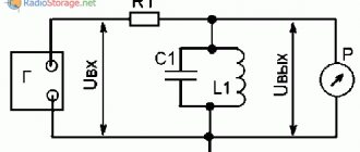
The electrical circuit of the filter is shown in Figure 2.
Rice. 2. Electrical diagram of the B series filter
The attenuation of the interference signal in dB is shown in Figure 3.
Rice. 3. Attenuation of the interference signal with B series filters
T series filters
Filters in this series (Figure 4) are high-performance radio frequency filters for power circuits of switching power supplies. The advantages of the series are excellent suppression of anti-phase and common-mode interference, compact dimensions. Low leakage currents allow the T series to be used in low power consumption applications.
Rice. 4. Appearance of the T series filter
The series includes two modifications - ET and VT, the technical characteristics of which are given in Table 2.
Table 2. Main technical characteristics of T series network filters
| Name | Maximum leakage current, mA | Operating frequency range, MHz | Electrical insulation strength (within 1 minute), V | Rated voltage, V | Rated current, A | ||
| ~120 V 60 Hz for currents 3; 6; 10 A (15; 20 A) | ~250 V 50 Hz for currents 3; 6; 10 A (15; 20 A) | "conductor-body" | "conductor-conductor" | ||||
| ET | 0,3 | 0,5 | 0,01…30 | 2250 | 1450 | ~250 | 3…20 |
| VT | 0,75 (1,2) | 1,2 (2,0) | |||||
The electrical circuit of the T series filter is shown in Figure 5.
Rice. 5. Electrical circuit of the T series filter
The attenuation of the interference signal in dB when the line is loaded onto a 50 Ohm matching resistor is shown in Figure 6.
Rice. 6. Attenuation of the interference signal with T series filters
Review of popular models
Let's look at the best surge protectors offered by manufacturers. The first of them is Buro BU-SP5 USB 2A-W. It has an organic appearance, takes up little space, and is relatively inexpensive. The average cost is 790 rubles. The case is white, equipped with 6 European sockets and 2 USB ports that allow you to charge mobile devices. The wire is 5 meters long, the maximum power is no more than 2.2 kW.
The ideal filter for connecting a computer is Pilot X-PRO. The length of the wire, depending on the model, varies from 1.8 to 7 meters. There are 5 euro sockets and one old style. It has an original appearance, reminiscent of a spacecraft in the best traditions of science fiction.
A special advantage is the presence of the Master Control function, which allows you to supply voltage to other consumers after turning on the main one. For example, a modem, printer and monitor can only turn on after the system unit starts. The average price is 1980 rubles.
The APC PMF83VT-RS is perfect for an LCD TV. Has connectors for connecting television and telephone cables. Provides faster data transfer rates while effectively suppressing RF noise and electromagnetic interference.
8 sockets are located at a distance from each other, which allows you to connect any power supply. Cord length – 3 meters. Equipped with light indicators indicating the absence of protection. Price – 3630 rubles.
USB socket: instructions for connection and setup. Review of the best manufacturers of USB sockets for the homePlug socket: all types and their characteristics. Instructions for correct and quick installation of a plug socket with your own hands
- How to choose wire fasteners - detailed instructions with examples
A properly selected surge protector will significantly extend the life of often expensive household appliances. You shouldn’t skimp on this - it’s better to pay now than to incur much higher repair costs later.
K series filters
K series filters (Figure 7) are general purpose radio frequency power filters. They are intended for use in power circuits with high-resistance loads. Excellent for cases where the line is subject to pulsed, continuous and/or pulsating radio frequency interference. Models with the EK index meet the requirements of standards for use in portable devices and medical equipment.
Rice. 7. Appearance of K series network filters
Filters with index C are equipped with a choke between the housing and the ground wire. The main electrical parameters of the K series network filters are given in Table 3.
Table 3. Basic electrical parameters of K series network filters
| Name | Maximum leakage current, mA | Operating frequency range, MHz | Electrical insulation strength (within 1 minute), V | Rated voltage, V | Rated current, A | ||
| ~120 V 60 Hz | ~250 V 50 Hz | "conductor-body" | "conductor-conductor" | ||||
| VK | 0,5 | 1,0 | 0,1…30 | 2250 | 1450 | ~250 | 1…60 |
| E.K. | 0,21 | 0,36 | |||||
The electrical circuit of the K series filter is shown in Figure 8.
Rice. 8. Electrical circuit of the K series filter
The attenuation of the interference signal in dB when the line is loaded onto a 50 Ohm matching resistor is shown in Figure 9.
Rice. 9. Noise reduction with K series filters
EMC series filters
Filters in this series (Figure 10) are compact and efficient two-stage RF power filters. They have a number of advantages: a high coefficient of attenuation of common-mode interference in the low-frequency region, a high coefficient of attenuation of anti-phase interference, and compact dimensions. The EMC series is focused on use in devices with switching power supplies.
Rice. 10. Appearance of EMC series filters
The main technical characteristics are given in Table 4.
Table 4. Basic electrical parameters of EMC series network filters
| Rated filter currents, A | Maximum leakage current, mA | Operating frequency range, MHz | Electrical insulation strength (within 1 minute), V | Rated voltage, V | Rated current, A | ||
| ~120 V 60 Hz for currents 3; 6; 10 A (15; 20 A) | ~250 V 50 Hz for currents 3; 6; 10 A (15; 20 A) | "conductor-body" | "conductor-conductor" | ||||
| 3; 6; 10 | 0,21 | 0,43 | 0,1…30 | 2250 | 1450 | ~250 | 3…30 |
| 15; 20; 30 | 0,73 | 1,52 | |||||
The electrical circuit of the EMC series filter is shown in Figure 11.
Rice. 11. Electrical diagram of two-stage filters of the EMC series
The attenuation of the interference signal in dB when the line is loaded onto a 50 Ohm matching resistor is shown in Figure 12.
Rice. 12. Attenuation of the interference signal with EMC series filters
Option 1: new building
Let's first consider the most optimistic scenario: a newly commissioned new building with a brand new substation;
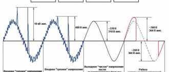
The wiring is made exclusively of copper with perfect installation, high-quality contacts that have not yet oxidized and automatic fuses for the appropriate current. It would seem that the voltage in the outlet should be as close as possible to an ideal sinusoid. Alas, even such an idyll can easily be ruined for a couple of months by a hop-up group with a broken-down tool invited by a neighbor for repairs: each electric motor in each dying angle grinder, drill or chipper will spark with all its might until its final feature, sending “death impulses” along the wiring of the house. .
This is just the beginning: the most active and restless residents will periodically connect industrial welding machines to their home network so that all neighbors in the entrance or house can “enjoy” pulsed noise in the form of stripes on TV and PC screens and a loud crackling sound in speakers and headphones.
So, even residents of relatively new microdistricts in large cities and metropolises with relatively new infrastructure are not protected from pulsed and high-frequency power supply interference - at least of local origin.
At a minimum, the first few years of a new home's life will inevitably be devoted to various repairs and alterations. In such a situation, it is possible that purchasing the most “powerful” surge protector is not necessary, but you cannot do without filtering the power voltage at all. For inexpensive options, you can take a closer look at domestic surge protectors. Its range includes many models that differ in the level of protection and the presence of additional functions.
The most affordable and simple solution for filtering mains voltage can be called the inexpensive mains filter ERA SF-5es-2m-I. The device is made in a fireproof housing, has a 2 m long cable and is equipped with five EURO format sockets with a grounding contact.
The maximum filter load is 2200 W (10 A), the maximum interference current is stated at 7000 A, and the maximum energy dissipation is 300 J with a maximum load voltage deviation of 275 V.
Surge filter ERA SFU-5es-2m-W
This filter is equipped with a power-on indicator, a surge noise filter, short-circuit and overheating protection. In addition, the device attenuates high-frequency interference (0.1 - 10 MHz) by 10-40 dB.
Those for whom high-frequency filtering is not critical can pay attention to the ERA USF-5es-1.5m-USB-W mains filter: with similar load and maximum current characteristics (minus the RF filter), this device is equipped with a switch and provides maximum energy dissipation up to 125 J, and is also equipped with two built-in USB ports for charging portable equipment and has wall mounting.
A slightly more expensive option is the ERA SFU-5es-2m-B surge filter, which combines all the advantages of the two filters mentioned above, including an RF filter, USB ports, wall mounting, a switch and maximum energy dissipation of up to 300 J, but is made in a reliable Polycarbonate body in stylish black color.
For those who need long cables, it makes sense to take a closer look at the Sven Optima series surge protectors for six outlets, supplied retail with a 1.8-meter, 3-meter or 5-meter network cable. These filters are designed for a maximum load of up to 2200 W, a maximum interference current of up to 2500 A and a maximum energy dissipation of up to 150 J with a load voltage deviation of up to 250 V.
Despite the low price, they are equipped with a built-in switch, power indicator, surge noise filter, short circuit protection and automatic overload protection.
The same class of devices includes the Pilot L 1.8 m surge protector from ZIS Company. A special feature of this filter is the presence of five EURO standard sockets plus one additional Russian-style socket, as well as support for a maximum interference current of up to 2500 A and a maximum dissipated energy of up to 800 J.
Standing apart from the line of surge protectors are single-socket solutions, which are present in the range of most manufacturers today. Owners of Hi-Fi and Hi-End equipment, especially those that were released 20 or more years ago, should definitely pay attention to these filters. An “individual” surge filter will protect the listener from clicks and other background sounds, and your favorite amplifiers, turntables, phono stages and soundboards from premature aging of already “not young” components.
Surge filter Pilot S-Max
For example, a single-socket surge protector Pilot BIT S with a maximum load of up to 3500 W, a maximum noise current of up to 10,000 A and dissipated energy of up to 150 J will provide complete protection of equipment using a surge noise filter, short circuit and overload protection.
Another interesting single-socket solution - the APC Surge Arrest P1-RS surge protector from Schneider Electric, despite its compact size, guarantees a maximum load of up to 16 A, a maximum interference current of up to 26,000 A and energy dissipation of up to 903 J. Such powerful protection is a success can be used as an adapter filter for a regular multi-socket extension cord.
APC P1-RS surge protector
EDP series filters
EDP series filters (Figure 13) are general purpose radio frequency filters for mounting on printed circuit boards. They have miniature dimensions and improved filtering of common mode noise at low cost and low leakage currents.
Rice. 13. Appearance of EDP series network filters
The main electrical parameters of the series network filters are presented in Table 5.
Table 5. Basic electrical parameters of EDP series network filters
| Maximum leakage current, mA | Operating frequency range, MHz | Electrical insulation strength (within 1 minute), V | Rated voltage, V | Rated current, A | ||
| ~120 V 60 Hz for currents 3; 6; 10 A (15; 20 A) | ~250 V 50 Hz for currents 3; 6; 10 A (15; 20 A) | "conductor-body" | "conductor-conductor" | |||
| 0,22 | 0,38 | 0,1…30 | 2250 | 1450 | ~250 | 1…10 |
The electrical circuit of the EDP series filter is shown in Figure 14.
Rice. 14. Electrical diagram of EDP series network filters
The attenuation of the interference signal in dB when the line is loaded onto a 50 Ohm matching resistor is shown in Figure 15.
Rice. 15. Attenuation of the interference signal with EMC series filters
FC series filters
A single-phase network filter for frequency converters is applicable in conditions of increased electromagnetic interference; it protects programmable logic controllers (PLCs) from negative influences from the AC supply network (Figure 16).
Rice. 16. Appearance of the FC series filter
The special design of the connecting terminals ensures safe connection and operation. The series has found wide application in the field of industrial automation. The main technical characteristics are given in Table 6.
Table 6. Basic electrical parameters of FC series network filters
| Filter type | Maximum leakage current, mA | Operating frequency range, MHz | Electrical insulation strength (within 1 minute), V | Rated voltage, V | Rated current, A | ||
| ~120 V 60 Hz for currents 3; 6; 10 A (15; 20 A) | ~250 V 50 Hz for currents 3; 6; 10 A (15; 20 A) | "conductor-body" | "conductor-conductor" | ||||
| No index | 3,80 | 6,70 | 0,01…30 | 2250 | 1450 | ~250 | 6…50 |
| Index B | 3,90 | 7,00 | |||||
The electrical circuit of the FC series filter is shown in Figure 17.
Rice. 17. Electrical diagram of FC series network filters
The attenuation of the interference signal in dB when the line is loaded onto a 50 Ohm matching resistor is shown in Figure 18.
Rice. 18. Attenuation of the interference signal with FC series filters
AYO series filters
Compact three-phase low-current network filters are designed to filter network noise in three-phase general industrial networks with a neutral wire (Figure 19).
Rice. 19. Appearance of three-phase surge protector AYO series
A special feature of the AYO series power filters is the presence of filtering circuits for both power lines and neutral. They are characterized by low leakage currents and small overall dimensions, which allows their use in compact equipment. The filter provides effective noise suppression over a wide frequency range from 100 kHz. The main technical characteristics of the AYO series network filters are discussed in Table 7.
Table 7. Main technical characteristics of AYO series network filters
| Rated filter currents, A | Maximum leakage current, mA | Operating frequency range, MHz | Electrical insulation strength (within 1 minute), V | Rated voltage, V | Rated current, A | ||
| ~120 V 60 Hz for currents 3; 6; 10 A (15; 20 A) | ~250 V 50 Hz for currents 3; 6; 10 A (15; 20 A) | "conductor-body" | "conductor-conductor" | ||||
| 3; 6; 10 | 2,00 | 3,00 | 0,1…30 | 1500 | 1450 | ~440 | 3…20 |
| 20 | 3,50 | 5,50 | |||||
The electrical circuit of the AYO series filter is shown in Figure 20.
Rice. 20. Electrical diagram of a three-phase network filter AYO series
The attenuation of the interference signal in dB when the line is loaded onto a 50 Ohm matching resistor is shown in Figure 21.
Rice. 21. Attenuation of the interference signal with AYO series filters
When choosing a surge protector, you must take into account its operating voltage, rated current and operating frequency band. An indicator of efficiency is the noise attenuation coefficient as the ratio of the noise signal at the filter input to its output level.
The characteristic operating temperature for all series considered is within the range of -10...40°C. At ambient temperatures above 40°C, the maximum permissible operating current is calculated using the formula:
The COMPEL company maintains in stock the most popular models of the considered network filters produced by TE Connectivity. These positions and their brief characteristics are shown in Table 8.
Table 8. KOMPEL warehouse items
| Name | Series | Number of load phases | Nominal filter voltage, V | Rated current, A | Dimensions LxWxH, mm |
| 1EB1 | B | 1 | 250 | 1 | 57x64x17 |
| 5EB1 | B | 1 | 250 | 5 | 66x64x19 |
| 6ET1 | T | 1 | 250 | 6 | 90x85x46 |
| 10ET1 | T | 1 | 250 | 10 | 119x113x45 |
| 15VT1 | T | 1 | 250 | 15 | 138x100x55 |
| 15VT6 | T | 1 | 250 | 15 | 151x100x55 |
| 10VK6 | K | 1 | 250 | 10 | 87x71x29 |
| 20VK6 | K | 1 | 250 | 20 | 87x85x38 |
| 40VK6 | K | 1 | 250 | 40 | 135x106x38 |
| 3EMC1 | EMC | 1 | 250 | 3 | 85x70x29 |
| 10EMC1 | EMC | 1 | 250 | 10 | 97x85x38 |
| 15EMC1 | EMC | 1 | 250 | 15 | 126x113x45 |
| 20EMC1 | EMC | 1 | 250 | 20 | 126x113x45 |
| 3EDP | EDP | 1 | 250 | 3 | 36x31x24 |
| 6EDP | EDP | 1 | 250 | 6 | 36x31x24 |
| 10EDP | EDP | 1 | 250 | 10 | 36x31x24 |
| 6AYO1 | AYO | 3 | 440 | 6 | 85x85x38 |
| 10AYO1 | AYO | 3 | 440 | 10 | 85x85x38 |
| 20AYO1 | AYO | 3 | 440 | 20 | 85x85x38 |
| 6FC10 | F.C. | 1 | 250 | 6 | 116x78x45 |
| 12FC10 | F.C. | 1 | 250 | 12 | 139x100x55 |
| 16FC10 | F.C. | 1 | 250 | 16 | 139x100x55 |
Anti-aliasing filters for power supply rectifiers.
Capacitive, inductive-capacitive, active smoothing filters. Schemes, properties, online calculator.
We talked thoroughly on the previous page about different types of diode rectifiers, exchanged a couple of phrases on the topic of the simplest capacitive filters, and the question of achieving the Kp within 10 -5. 10 -4 just hung in the air - the nominal capacity of the smoothing capacitor turns out to be very considerable.
The ripple factor of the rectified voltage Kp is the most important parameter of the rectifier. Its numerical value is equal to the ratio of the amplitude value of the pulsating voltage to its constant component. Let me remind you of the excerpt from the printed publication given on the previous page:
“The ripple coefficient is chosen independently depending on the expected load, allowing for direct current power supply of a very specific “purity”: 10 -3. 10 -2 (0.1-1%) - small-sized transistor radios and tape recorders, 10 -4. 10 -3 (0.01-0.1%) - radio and intermediate frequency amplifiers, 10 -5. 10 -4 (0.001-0.01%) - preliminary stages of audio frequency amplifiers and microphone amplifiers.”
In addition, the concept of filtering coefficient (smoothing coefficient) can be used in the characteristics of rectifiers. The filtering coefficient, also known as the smoothing coefficient , is a value numerically equal to the ratio of the ripple coefficient at the filter input to the ripple coefficient at the filter output Kc = Kp-in/Kp-out . For multi-link filters, the filtration coefficient is equal to the product of the filtration coefficients of individual links.
In low-current circuits, the issue of reducing ripple is solved easily and radically - by using integral stabilizers. The ripple suppression parameter (Ripple Rejection) for such mass-produced ICs is at least 50 dB (360 times the voltage), which, with a high “purity” of the output voltage, makes it possible to reduce the capacitance of electrolytes by 5-10 times.
If the developer does not have the opportunity (or desire) to include voltage stabilizers in the device, then inductive-capacitive or active smoothing filters .
Let's start with filters made of inductive elements - chokes and capacitive elements - capacitors.
Fig.1
Figure 1a shows a diagram of the simplest capacitive anti-aliasing filter. The principle of operation is the accumulation of electrical energy by the filter capacitor and the subsequent release of this energy to the load.
In order not to be limited to 50 Hz power supplies, but also to be able to calculate filters for pulsed UPSs, I will give universal formulas that take into account the frequency of the input signal F : C1 = In/(3.14×Un×F×Kp) for half-wave rectifiers and C1 = In/(6.28×Un×F×Kp) - for full-wave. Kp is the ripple coefficient equal to the ratio of the amplitude value of the ripple voltage to its constant component, and F is the frequency of the alternating voltage at the input of the diode rectifier.
Let's move on to inductive-capacitive LC filters. ATTENTION. The need for this kind of circuits arises exclusively in cases where it is necessary to obtain a low level of ripple in sufficiently powerful network power supplies, or in high-frequency switching UPSs. This is due to the fact that for the LC filter to operate effectively, the inductive reactance of the XL coil at the suppression frequency tends to be significantly greater than Rн. And this, in turn, leads to the fact that under conditions of low frequencies and low currents (high Rн), the inductance of the inductor turns out to be unreasonably high.
Literature
1.
2. Corcom Product Guide, General purpose RFI filters for high impedance loads at low current B Series, TE Connectivity, 1654001, 06/2011, p. 15
3. Corcom Product Guide, PC board mountable general purpose RFI filters EBP, EDP & EOP series, TE Connectivity, 1654001, 06/2011, p. 21
4. Corcom Product Guide, Compact and cost-effective dual stage RFI power line filters EMC Series, TE Connectivity, 1654001, 06/2011, p. 24
5. Corcom Product Guide, Single phase power line filter for frequency converters FC Series, 1654001, 06/2011, p. thirty
6. Corcom Product Guide, General purpose RFI power line filters - ideal for high-impedance loads K Series, 1654001, 06/2011, p. 49
7. Corcom Product Guide, High performance RFI power line filters for switching power supplies T Series, 1654001, 06/2011, p. 80
8. Corcom Product Guide, Compact low-current 3-phase WYE RFI filters AYO Series, 1654001, 06/2011, p. 111.
Obtaining technical information, ordering samples, delivery - e-mail
Network and signal EMI/RFI filters from TE Connectivity. From board to industrial installation
TE Connectivity is a world leader in the design and manufacture of surge protectors for effective suppression of electromagnetic and radio frequency interference in electronics and industrial applications. The model range includes more than 70 series of devices for filtering both power circuits from external and internal sources, and signal circuits in a wide range of applications.
The filters have the following design options: miniature for installation on a printed circuit board; cabinets of various sizes and types of connection of supply lines and load lines; in the form of ready-made power connectors and communication connectors for network and telephone equipment; industrial, made in the form of ready-made industrial cabinets.
Surge filters are produced for AC and DC applications, single- and three-phase networks, covering the range of operating currents 1...1200 A and voltages 120/250/480 VAC, 48...130 VDC. All devices are characterized by a low voltage drop - no more than 1% of the operating voltage. The leakage current, depending on the power and design of the filter, is 0.2...8.0 mA. The average frequency range for the series is 10 kHz...30 MHz. AQ series is designed for a wider frequency range: 10 kHz...1 GHz. Expanding the applications of its products, TE Connectivity produces filters for low and high impedance load circuits. For example, high impedance filters of the EP, H, Q, R and V series for low impedance loads and low impedance filters of the B, EC, ED, EF, G, K, N, Q, S, SK, T, W, X, Y and Z series for high impedance loads.
Communication connectors with built-in signal filters are available in shielded, paired and low-profile designs.
Each filter produced by TE Connectivity undergoes double testing: at the assembly stage and already in the form of a finished product. All products comply with international quality and safety standards.
•••
What varieties are there?
Depending on the level of security provided, network filters are divided into the following types:
Essential. Provides basic security capabilities. Suitable for simple household appliances.
Home/Office. Universal devices with an optimal combination of price and quality. Can be used with most household appliances.
Performance. Professional equipment for complex electronic devices that are extremely sensitive to the slightest changes. Provides maximum protection, but is much more expensive.
The difference between the presented types can be assessed, for example, by the ability to smooth out bursts of energy. If for a regular filter it does not exceed 960 J, then for a professional one it is 2500 and higher.
However, you must remember that the characteristics stated in the instructions for the selected model will only be achieved when used in sockets with grounding. In networks where it is not provided, the efficiency of these devices is somewhat reduced.