Components of three-phase Resanta ASN
Before moving on to repairing the voltage stabilizer, let’s first take a brief look at what our box consists of and how it works.
So, as I already said in the previous article about three-phase stabilizers, a three-phase stabilizer is three single-phase ones. The same is the case with Resanta asn-20000/3-em:
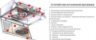
Three-phase electromechanical stabilizer - device
It can be seen that this stabilizer consists of three identical parts - three single-phase stabilizers, each of which stabilizes only its own phase. This applies to such common single-phase models as ASN 10000 1 em, etc.
That is, even if there is a significant imbalance in the phase voltages at the input, the output for all phases will be 220 V + -3%. You can read more about the parameters of such stabilizers in the instructions, which can be downloaded at the end of the article.
And if the phase imbalance occurred as a result of a zero break, you can read about the consequences of this here. A three-phase stabilizer will correct the situation to a certain extent, and if it fails, it will turn off and save the consumer.
Autotransformer
The heart of an electromechanical transformer is a step-up autotransformer. This “heart” beats in time with the change in voltage at the input of the stabilizer, trying to equalize it to normal.
Step-up autotransformer - the heart of the electromechanical stabilizer
Why is a step-up autotransformer used rather than a step-down autotransformer? Because stabilizers most often have to deal with reduced input voltage. But this does not mean, of course, that it cannot reduce the overestimated input voltage. However, I will not describe the principles of operation of the autotransformer here.
Let's look at the stabilizer device in the following photo:
Stabilizer device with explanations
The first thing you need to understand is that an autotransformer consists of two equal parts connected in parallel to increase power. Accordingly, there are two windings, two brushes ride on them (the brush is not visible in the photo, it is indicated by an arrow).
Since the brush is a contact, and a rather poor one at that, it gets hot. This is normal, but a radiator is provided to cool it. A temperature sensor is installed in the brush radiator, which, when the permissible temperature is exceeded (105°C), opens the control circuit and disconnects the load from the stabilizer output.
The motor moves brushes along the surface of the winding, adjusting the voltage. At the end of the brush stroke, corresponding to the lowest voltage (140 V), limit switches are installed to stop the motor. This is the most difficult operating mode, since the output power of the stabilizer drops. If the voltage drops further, the autotransformer can no longer cope, and the entire stabilizer turns off. This occurs by opening the KL relay contacts (see circuit diagram below).
A temperature sensor is attached (glued) to the transformer body, which, when overheated above 125 °C, opens the control circuit, protecting it from further thermal destruction.
Both types of sensors are self-healing. That is, when it cools down, the control circuit is assembled, and the stabilizer is ready for use again.
Electronic board
What makes the autotransformer motor move? This is an electronic circuit that measures the input phase voltage and outputs voltage to a servo motor, which moves the autotransformer brush, changing the output voltage to the desired level:
Electronic control board
The above photo shows the consequences of eliminating a common malfunction - breakdown of bipolar power transistors through which the engine is controlled. Along with them, resistors also burn out, which initially had a power of 2W, but were replaced by 5W. But for malfunctions and repairs - at the end of the article.
Control circuit starter
This starter is necessary to protect (turn off) the stabilizer and load in case of unavailability, malfunction or overheating.
Control circuit starter
Let's take a closer look at its operation when analyzing the electrical circuit diagram.
Electrical diagram of a three-phase voltage stabilizer Resanta
Let's consider the circuit of a single-phase electromechanical stabilizer Resanta ASN - 10000/1-EM. Let's take this circuit, because, as I said, three single-phase ones are one three-phase stabilizer.
The diagram, as usual, can be zoomed in and then enlarged to 100% by clicking on the arrows in the lower right corner of the image. Then right-click, Save Image As... etc.
How to print such a large diagram - be sure to read this article.
I downloaded the diagram on the Internet, author, respond!
Electrical diagram of voltage stabilizer Resanta-ASN-10000-1-em
For ease of perception, I have marked the main structural parts on the diagram.
Typically, the voltage stabilizer uses ha17324a - this is an operational amplifier chip, it compares the voltages and outputs a signal to transistors TIP41 and TIP42, which supply power to the autotransformer motor.
I will not fully consider the operation of electronics; if you are interested, ask questions in the comments.
Now - how does this circuit differ from the circuit of a three-phase stabilizer:
The main difference is in the control circuit. In the single-phase version (in the diagram) it can be seen that the control circuit for powering the KM starter is assembled as follows: Neutral – On-delay relay KL – Thermal relay 1 transformer (125°C) – Thermal relay 2 transformer (125°C) – Thermal relay 1 brush (105 °C) – Brush thermal relay 2 (105°C). Total – 5 contacts. If this circuit is assembled, the KM contactor turns on and voltage is supplied to the output of the stabilizer.
In the three-phase version, in order for the stabilizer to start, 15 (!) conditions must be met - this is exactly how many contacts must be closed in order for the KM contactor to turn on.
During normal operation, when the stabilizer is turned on, you can hear how the CC is assembled - after about 10 seconds there is a click (on one of the electronic boards), then another one, and the third click starts the contactor and the entire stabilizer.
What is a control circuit, its difference from emergency and thermal circuits, and why the repair of any serious automation must begin with checking the control circuit - it is described in detail in my other article, I highly recommend it if you have read this far)
The second is the absence of a cooling fan; in this case, the cooling is natural.
Third, there is no bypass; its implementation will require the use of a three-pole contactor with normally closed contacts (or two conventional contactors), this is expensive, so the manufacturer did without it.
I also write about this problem in an article about connecting a gasoline generator to a house via an automatic transfer switch.
Well, then - the logical differences: Three current transformers, three ammeters, etc.. Let’s not pour water, but let’s move on to what I intended this article for - repairing an electromechanical voltage stabilizer with my own hands.
Repair of electromechanical voltage stabilizers
The main problem with such stabilizers is overheating. It is absolutely necessary to carry out maintenance of the stabilizer once every 1-2 months, depending on operating conditions. And the repair of voltage stabilizers must begin with cleaning.
The problem of overheating manifests itself primarily due to the fact that the graphite brush, when moving along the surface of the transformer, inevitably wears out, and its particles, along with dust and other debris, remain on the contact track.
Now, when the brush continuously “crawls” over the surface, it begins to heat up more, spark, the debris burns and burns to the copper surface. In the future, this negative effect will increase like an avalanche, and if measures are not taken, it will reach irreversible limits, when cleaning will no longer help.
Of course, thermal sensors will save the situation - these are the first “bells”. If the stabilizer suddenly starts to turn off on its own, you should urgently call a specialist and clean the surface.
Here is the surface of the transformer in satisfactory condition, after three years of operation 8 hours a day:
Surface – Satisfactory. And this is after washing with alcohol.
And here is what indifference to the state of the stabilizer can lead to. This is the same stabilizer, a different phase:
Surface condition – Very bad
Even if you clean off this deposit, the cross-sectional area of the wire will irreversibly decrease by 20-30%, which will increase the heating of the wire and brush, and lead to the pessimistic processes described above:
The surface of the autotransformer is close. The wire insulation is burnt out, an interturn short circuit is possible. The epoxy also fell off due to overheating.
Only “zero” sandpaper will help here. You need to clean as you go with the brush, then rinse thoroughly with alcohol and wipe dry with a clean cloth.
Servomotor repair
Another breakdown is a malfunction of the servomotor when it stops moving the brush. The engine must be removed, cleaned, blown, and lubricated. Since a DC motor with brushes is used, you can try to idle it in both directions from a DC source with a voltage of about 5 V.
This way, without disassembling it, you can clean its brushes a little, because the engine rotates (or rather, turns) only at an angle of up to 180 degrees.
Electronic board repair
The engine may not turn over because there is no power coming to it. The power comes from the control board, from bipolar transistors. A pair of complementary transistors TIP41C and TIP42C is used, since the power supply to the circuit is bipolar. Transistors must be replaced in pairs, even if one is intact. And only one manufacturer.
The datasheet (documentation) for transistors can be downloaded at the end of the article.
Also in the same circuit, 10 Ohm resistors burn out (this is a consequence of the breakdown of transistors). When replacing resistors, nothing prevents you from increasing their power to 3 or 5 W, increasing operational reliability.
Well, replacing relays, transistors, limit switches and other small things - depending on the situation.
Power section repair
The power part includes autotransformers (I have already said enough about them). And also - a contactor and an input circuit breaker, whose contacts and terminals are lit. It must be periodically stretched, cleaned, and, if necessary, replaced.
Resanta stabilizer does not start
Like any complex electronic device, the voltage stabilizer sometimes fails, turns itself off or knocks out the circuit breakers, or at least does not work correctly, hums or beeps. There may be several reasons, depending on the specific situation, and this may depend on improper use or depend directly on the type and electronic content of the device itself.
Attempts by owners to repair such a complex device themselves can be justified only in the case of superficial causes of failure and little understanding of the principle of operation of the device.
But this does not always lead to the desired result, and often can even lead to complete breakdown of the control board and power switches, which will ultimately increase the cost of repairs significantly. Therefore, it is better to entrust the repair to specialists, especially if the stabilizer is under warranty. But we will still look at the main causes of malfunctions and methods for eliminating them.
A stabilizer of any type is a complex electronic device and often measuring instruments and at least some knowledge of radio engineering will be needed to identify a malfunction.
As a rule, all voltage stabilizers have a whole protection system, the purpose of which is to protect power elements from combustion, protection for excess power, overheating of the device, as well as protection of the output voltage from abnormal voltage surges. Basically, all the protection of the stabilizer is implemented on the control board, the complexity of the circuit of which depends on the type of stabilizer.
The most difficult thing to identify is a fault in a stabilizer based on triac switches; a complex control circuit requires checking with an oscilloscope, or in extreme cases, you can use the method of sequentially checking each element of the circuit.
In relay voltage stabilizers, a common cause of failure is the relay that switches the transformer windings. With frequent unstable voltage in the network, the relays make many switches throughout the day; over time, the relay contacts burn out, they can still stick, and sometimes the relay coil itself burns out. In such cases, an error message may appear, the stabilizer may simply turn off, or it may be much worse, even leading to an internal short circuit with the corresponding consequences.
The easiest to repair can be called a servo-drive stabilizer; after removing the cover of the device, you can visually examine its behavior and try to identify the cause with logical conclusions.
Modernization proposals
If the voltage fluctuates approximately in one narrow range, and the transformer track is burned out in this area (as in the last photo), I suggest changing the circuit so that the brush “travels” over another area. To do this, you need to resolder the wire from the lower end of the winding (N) several turns higher (see diagram). Of course, on both parts of the autotransformer. As a result, the brush will slide along another, relatively clean part of the path. The disadvantage of this solution is the narrowing of the adjustment range.
Another solution to this problem is to buy new transformers, which is not economically feasible - after three years of operation it is better to buy a new stabilizer.
Another improvement is to install 12 V coolers (fans) on each transformer, which would blow on the brushes. Ideally, 6 fans. They will literally blow away specks of dust. This will significantly extend the life of the stabilizer.
How do you repair such stabilizers? I look forward to constructive criticism and exchange of experience in the comments.
To increase the life of transistors and servomotor
My reader and subscriber of the SamElectric.ru group Andrey Altukhov shared his circuit, which avoids overheating of transistors and increases the life of the motor due to the fact that the stabilizer does not respond to small (2-3 V) changes in the input voltage. The diagram and description are given “as is”; whoever repeats the modification - write in the comments!
Here's what Andrey writes:
The comments offered options on how to save the board and electric motor from premature failure. After the servo motor died twice in 2 years from overheating of the brushes and the control board in the area of the power transistors turned black, I decided to delve deeper into the issue. I played around with the gain factors of the op-amp, twisted it back and forth, but still the linear mode of operation did not go away.
I thought I could quickly solve the problem by installing a zener diode or a diode at worst, but the voltage levels are too low to make any difference. It is also possible to build something with a dead zone on transistors, but this is all a grandiose stucco on the board. Ideas swarmed in my head to insert a second op-amp and connect it to the break in the control circuit.
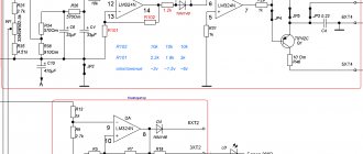
And then my father, looking over his shoulder, discovered in the diagram a completely unused (at least in the single-phase version) operational amplifier, already soldered on the board on legs 12, 13, 14 with output to pin 4XT2, which was simply hanging in the air. And then there were estimates of gain factors and feedback. As a result, this scheme was born. (picture based on one taken from the article).
Stabilizer circuit with response threshold
The threshold element is two back-to-back diodes connected in parallel. resistors R101 and R102 regulate the feedback and ultimately give the width of the dead zone. I settled on the 10k and 2.2k ratings which gives about 3V AC insensitivity. As soon as the voltage in the network changes to a larger value, one of the diodes opens and the electric motor is supplied not with a gradually increasing voltage, but immediately with a threshold, allowing the engine to immediately take a step. In addition, correction of the output voltage with a trimmer was required to set the output voltage. Well, with the second file I’m attaching what the printed circuit board looks like after modification.
Stabilizer printed circuit board after modification
Yes, in the original circuit, instead of a motor, I connected a small light bulb and a voltmeter. The tension gradually increases in either direction. In my circuit, the motor turns on when there is already a more serious voltage deviation. Moreover, if the voltage suddenly jumps in either direction, there will be no delays in operation.
Refinement affects accuracy, but in real life it does not matter much. The output voltage in my case has the right to vary +- 3 volts from the set nominal value. This is an inevitable price to pay for less nervousness of the servo. You can increase the gain of the first op-amp (blue text in the diagram) and get +- 1.5 volts.
There is one more moment. All experiments were carried out on a stabilizer in which the motor was replaced with a more expensive version with graphite brushes. It was not possible to check how it will spin with a standard motor.
Shows no signs of life or other damage at all
The most frightening malfunction is when, after applying voltage, neither the indicators light up nor the output voltage appears, i.e. when the voltage stabilizer does not work at all. In this case, the control board may fail. Most often, repairs begin with a visual inspection, paying attention to:
- burnt out paths;
- swollen electrolytic capacitors;
- burnt, cracked or exploded board components;
- microcracks on soldered contacts and cold soldering.
Photo and diagram of new boards for electromechanical Resanta
Question from a reader.
I wanted to ask you in which direction should I dig, what should I check. I have a Resanta 15 kW 3 phase stabilizer.
When turned on, it drives two autotransformers to their extreme positions due to high voltage and only one works normally; when we rearranged the control boards, I found out that the problem is in them. I checked all the autotransformers with the working board. What can this behavior give on a board? Are these boards repairable?
Photo and question from here.
Why use a stabilizer
The voltage stabilizer ensures automatic maintenance of the set load in the network.
Single-phase and three-phase, electromechanical, electronic modifications of devices are designed to prevent voltage fluctuations and failures on the power line. The rectifier provides:
- constant power supply of household devices in conditions of voltage drop or increase;
- checking network parameters;
- interference filtering;
- protection against distortion and line fluctuations;
- stability of equipment power supply during long-term power surges;
- control of electrical wiring inputs and outputs;
- automatic maintenance of the set load in the network.
Stabilization devices are easy to use and long-lasting.