How to restore an electric motor armature
Do-it-yourself collector repair using galvanic extension
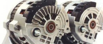
This is what collectors look like that are quite suitable for restoration.
To the left, from the stove, with the lamellas completely burnt out to the insulator, you will have to wind a bare wire with a diameter of about 0.2 mm onto it turn to turn. In the middle of the starter, but already machined for extension. It shows that one lamella has burned out to the base and the rest are extremely worn, but the fastening of the lamellas is not broken, and the wires are welded to the lamellas. Standard diameter 45mm machined to 41mm. On the right, the manifold is also from the stove, quite suitable for restoration without modifications, you just need to clean it.
The anchor for the extension will have to be prepared, since it is not quite ordinary, and an improvised bathtub will have to be made.
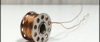
Half a plastic bottle is suitable for this. The armature shaft needs to be wrapped with tape, and the end of the commutator should be covered with plasticine so that copper does not accumulate on the ends of the lamellas in vain and so that the electrolyte does not leak between the shaft and the insulator of the commutator; contact of the electrolyte with iron is unacceptable. You need to wind a cork from PVC electrical tape so that it fits tightly into the neck of the bottle from the inside.
At the motor commutator, you need to use a piece of bare wire to connect all the lamellas well together and hang them on the crossbar in a simple jar of electrolyte so that the electrolyte does not touch the hooks, but completely covers the area of wear.
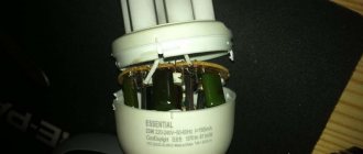
The location of the collector is in the electrolyte, the anode is a tire from a burnt-out starter, its total area should be approximately twice as large as the surface to be built up. The shank is rolled up into a spiral, slightly larger than the diameter of the vessel and, when placed in the vessel, fits tightly to the wall. The minus of the power source is connected to the extension part, the plus to the busbar. The current is selected at the rate of 1.5A per 1 dm2. You can power it from a phone charger, and regulate the current by turning on light bulbs of different power in series. Light bulbs are also needed to protect against possible short circuits in the bathtub.
Electrolyte composition:
- copper sulfate - 200g
- sulfuric acid 1.84 - 40g
- alcohol - 5g
- boiled water - 800ml.
- alcohol can be replaced with triple the amount of vodka.
A day later we get a not entirely attractive appearance of the extended collector.
But after grooving it already looks like this, since copper builds up, although not evenly, but much more than necessary.
Of course, the volume of the bath is small, you can experiment with the composition of the electrolyte, but is this necessary? With this mode, the copper builds up to be very hard, although not evenly. You can cut the grooves between the lamellas with a drill, or simply with a sharpened hacksaw blade, and be sure to check for the absence of short circuits between the plates.
This is what the starter armature, ready for assembly, looks like, its diameter has become 1 mm larger than the standard one, but this does not interfere with anything, but takes longer. You can see by a small chip where the burnt lamella was. On the right is the motor armature ready for winding, the collector is also enlarged by 1 mm. This method can be used to restore almost any collector, unless, of course, it fell apart.
Rewinding the motor armature
Of great importance in maintaining the performance of any electrical device equipped with an electric motor and extending its service life is carrying out scheduled preventive maintenance with a certain regularity. This will help prevent and eliminate various problems.
Why is it necessary to rewind the armature of an electric motor?
But still, sometimes it may be necessary to rewind the starter armature winding. This may be due to the following reasons:
- There is damage to the winding or commutator.
- The turns of the winding are closed together.
- The lamellas were sintered due to excessive heating.
- The motor winding has burnt out.
The starter winding is placed in insulation, which provides effective protection against overheating. But if the motor has been used for a very long time, it will wear out and its winding may be damaged. She'll just burn out. Sometimes rewinding the armature winding will cost the owner more than purchasing a new starter. This is due to the fact that additional spare parts will be required. In addition, finding something suitable to replace it can sometimes be very difficult. Then all that remains is to balance and rewind the armature winding.
It must be said that the rewinding process is quite complex and painstaking, requiring a lot of time. Therefore, it is not possible to rewind the armature winding efficiently in every workshop.
Stages and features of rewinding an electric motor armature
Similar actions can be carried out when major or current repairs are carried out. In terms of technology, the process is similar to the case when electric motor coils are repaired.
- First, the unit undergoes a visual inspection. Determine the cause of the failure. And this could be a short circuit or the winding has simply burned out.
- After this, the technician will remove the winding turns with extreme care. At the same time, they try to preserve all sectional bends as much as possible.
- Detected defects in the winding shape are corrected using a template.
- If significant wear of the elements is detected, they are replaced with new parts. For example, they change the bearing sleeve, and if a short circuit occurs, install a new manifold.
- The old insulation is dismantled, and the groove is subjected to a new sealing.
- The craftsman will then carefully place the winding sections into the plates. In this case, the groove pitch is taken into account. Insulating material is laid in the space between the turns. If we are talking about a starter for an industrial unit, then a cord is used as it. Simple models usually use insulating cardboard.
- Then the sections must be pressed in, and the winding must be secured to the collector plates.
- After this, tests must be carried out.
- Then the anchor must be soaked and dried. A special varnish is used for this. It will provide protection to the anchor and at the same time serve as a conductor. The drying process is carried out in special ovens
Angler anchor device
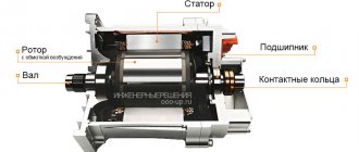
The armature of the angle grinder motor consists of a conductive winding and a magnetic circuit into which the rotation shaft is pressed. It has a drive gear at one end and a commutator with lamellas at the other. The magnetic core consists of grooves and soft plates coated with varnish to insulate them from each other.
Grinder anchor diagram
Two conductors of the armature winding are laid in the grooves according to a special pattern. Each conductor makes up half a turn, the ends of which are connected in pairs on lamellas. The beginning of the first turn and the end of the last are in the same groove, so they are closed to one lamella.
How to check the angle grinder's anchor for serviceability
Types of armature faults:
- An insulation breakdown to ground is a short circuit of the winding to the metal rotor body. Occurs due to the destruction of insulation.
- Wiring of collector terminals.
- Uneven wear of the commutator.
- visually;
- multimeter;
- light bulb;
- special devices.
If the armature is faulty, the motor overheats, the winding insulation melts, and the turns become short-circuited. The contacts connecting the armature winding to the collector plates are unsoldered. The current supply stops and the motor stops working.
Types of armature diagnostics:
Standard diagnostics
Before taking the diagnostic device, inspect the anchor. It may be damaged. If the wiring is melted, the burnt insulating varnish will leave black marks or a specific smell. You may see bent or crumpled coils or conductive particles, such as solder residue. These particles cause short circuits between turns. The lamellas have curved edges, called cockerels, to connect to the winding.
Due to disruption of these contacts, the lamellas burn out.
Other commutator damage: raised, worn or burnt plates. Graphite from the brushes may accumulate between the lamellas, which also indicates a short circuit.
Bent commutator plates
How to check with a multimeter
- Set the resistance to 200 ohms. Connect the probes of the device with two adjacent lamellas. If the resistance is the same between all adjacent plates, then the winding is working. If the resistance is less than 1 ohm and very close to zero, there is a short circuit between the turns. If the resistance is two or more times higher than average, then there is a break in the winding turns. Sometimes when there is a break, the resistance is so great that the device goes off scale. On an analog multimeter, the arrow will go all the way to the right. But digital won’t show anything.
Diagnosis of the armature winding with a multimeter
Video: how the check is carried out
If you don't have a tester, use a 12-volt light bulb with up to 40 watts.
How to check the rotor of an angle grinder using a light bulb
- Take two wires and connect them to the lamp.
- Make a break on the negative wire.
- Apply voltage to the wires. Place the ends of the break against the collector plates and rotate it. If the light bulb lights up without changing brightness, then there is no short circuit.
- Perform a short circuit test to the iron. Connect one wire to the lamellas and the other to the rotor iron. Then with the shaft. If the light is on, it means there is a ground fault. The winding closes to the rotor housing or shaft.
Possible malfunctions of the commutator motor
Sometimes even people familiar with the structure of the mechanism have little idea how to check a commutator motor. Below we will talk about all possible malfunctions and ways to identify and eliminate them.
- Broken contacts. This is indicated by active sparking.
- Interturn short circuit (short circuit of windings in the collector). It also causes sparking.
- Wear of the brush-collector unit. At the same time, it turns black and sparking appears. Usually the problem is solved by replacing old elements with new ones. To remove the assembly, move the lock and unscrew the mounting bolt (depending on the engine model).
- Darkening of the contact part of the collector. Often it is enough to clean it with fine sandpaper.
- Formation of a groove at the point of contact of the brushes with the commutator. It is necessary to perform the grooving of the unit on the machine.
- Bearing wear. This malfunction can be determined by increased vibration of the housing during engine operation and beating of the cartridge. In this case, bearing replacement is required.
- The armature touches the stator. Sometimes replacing the armature is enough, but in some cases you will have to replace both the armature and the stator.
- Control failure on the microcontroller. Installing a new microcontroller is the optimal solution to the problem.
- Burnout or breakage of windings. Pay attention to their color and integrity. Blackening of the entire winding body or part thereof indicates burnout; a break is easily determined by visual inspection. In this case, they need to be replaced or rewinded.
- Graphite dust in the space between the lamellas. Your appliance just needs cleaning.
- Burnout of wire insulation. A characteristic odor will indicate this problem.
In all of the above cases, restoring the electric motor manifold with your own hands is quite possible if you have the necessary spare parts and tools. Only if you do not have experience in rewinding windings, it is better to contact the appropriate service. After troubleshooting, reconnect all parts in reverse order.
Checking with a short-circuited turns indicator (SCI)
There are anchors where the wires connected to the collector are not visible due to being filled with an opaque compound or due to a bandage. Therefore, it is difficult to determine the commutation on the commutator relative to the slots. An indicator of short-circuited turns will help with this.
This device is small in size and easy to use.
First check the anchor for breaks. Otherwise, the indicator will not be able to detect a short circuit. To do this, use a tester to measure the resistance between two adjacent lamellas. If the resistance is at least twice the average, then there is a break. If there is no break, proceed to the next step.
The resistance regulator allows you to select the sensitivity of the device. It has two lights: red and green. Adjust the regulator so that the red light starts to light. On the indicator body there are two sensors in the form of white dots located at a distance of 3 centimeters from each other. Attach the indicator with the sensors to the winding. Rotate the anchor slowly. If the red light comes on, it means there is a short circuit.
Video: IKZ at work
Checking the commutator motor with a multimeter
Let's say a visual inspection did not produce results - at first glance, all components are intact, no breaks were found, and there is no burning smell. In this case, check the device and its elements using a special device - a multimeter. The process consists of several stages:
- Set the device to resistance measurement mode up to 200 Ohms.
- Ring the paired terminals of the stator windings on the lamellas. The resistance values must be the same.
- Check the armature body and lamellas. Ideally, the resistance value tends to infinity.
- Ring the winding terminals. If there is no resistance in one or more circuits, the motor is faulty.
- Check the circuit between the stator housing and the winding terminals. If there is a breakdown in the housing, operation of the unit is impossible.
- Ring the rotor by placing the tester probes on the commutator at the maximum distance from each other. When the multimeter shows a value, turn the rotor slightly until the probes connect to the next winding. Check all windings in this way. If the resistance value in each circuit is the same or differs very slightly, the unit is working.
You should not immediately take a “jammed” device for repair or throw it away, as many people prefer to do. You will save money if you know how to restore the electric motor commutator yourself. The process is not too complicated and does not take much time, and the mechanism can last for a long time.
Diagnostics with an armature testing device (throttle)
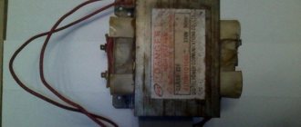
The armature testing device determines the presence of an interturn short circuit in the winding. The inductor is a transformer that has only a primary winding and a magnetic gap cut out in the core.
Anchor testing device diagram
When we place the rotor in this gap, its winding begins to act as the secondary winding of a transformer. Turn on the device and place a metal plate, such as a metal ruler or hacksaw blade, on the anchor. If there is an interturn short circuit, the plate will vibrate or be magnetized towards the armature body due to local oversaturation of iron. Rotate the armature around the axis, moving the plate so that it lies on different turns. If there is no short circuit, the plate will move freely along the rotor.
Anchor testing device
Video: How to make a throttle with your own hands and check the anchor
How to repair an anchor at home
A third of screwdriver failures occur due to the anchor. With everyday intensive operation, malfunctions can occur within the first six months, for example, if the brushes are not replaced in a timely manner. With gentle use, the screwdriver will last a year or more.
The anchor can be saved if the balance is not disturbed. If during operation of the device you hear an intermittent hum and there is strong vibration, then this is an imbalance. This anchor must be replaced. And the winding and commutator can be repaired. Small short circuits are eliminated. If a significant part of the winding is damaged, it can be rewound. Worn and badly damaged lamellas should be sharpened, extended or soldered. In addition, you should not undertake anchor repairs if you are unsure of your capabilities. It is better to replace it or take it to a workshop.
Collector groove
Over time, wear from the brushes forms on the commutator. To get rid of it, you need to:
- Grind the commutator using cutters for longitudinal grinding, that is, through cutters.
Passing straight cutter
Don't forget to clear the rotor of chips to prevent a short circuit.
Video on the topic
How to rewind an anchor
Before disassembling the armature, write down or sketch the direction of the winding. It can be left or right. To determine it correctly, look at the end of the armature from the commutator side. Wear gloves and take sharp wire cutters or a hacksaw. Remove the winding end parts. The collector needs to be cleaned, but it is not necessary to remove it. Carefully, without damaging the slot insulators, knock out the rods of the remaining parts of the winding using a hammer and metal chisel.
Video: Removing the winding
Using a needle file, without damaging the insulator film, remove the remaining impregnation. Count the conductors in the slot. Calculate the number of turns in the section and measure the diameter of the wire. Draw a diagram. Cut cardboard sleeves for insulation and insert them into the grooves.
Video: Winding left and right
After winding, weld the section leads to the collector cocks. Now check the winding with a short circuit tester and indicator. Proceed with impregnation.
Instructions for impregnation (taking into account the speed controller)
- After making sure that there are no problems, send the armature to the electric oven to warm up for better flow of the epoxy resin.
- After warming up, place the anchor on the table at an angle for better spreading over the wires. Apply resin to the frontal area and slowly rotate the anchor. Drip until glue appears on the opposite frontal part.
Impregnation at an angle
Drying the anchor in air before polymerization
At the end of the process, lightly grind the commutator. Balance the anchor using a dynamic balancer and an angle grinder. Now make the final grind on the bearing. It is necessary to clean the grooves between the lamellas and polish the collector. Make a final check for opens and shorts.
The peculiarity of the winding for angle grinders with adjustable speed is that the rotor is wound with a power reserve. Current density affects the number of revolutions. The wire cross-section is too high and the number of turns is too low.
Where to begin?
Since the structure of the rotary hammer is simple, the repair of the makita rotary hammer must begin with its disassembly. It is best to disassemble the hammer drill according to the already proven procedure.
Algorithm for disassembling a hammer drill:
- Remove the back cover on the handle.
- Remove the electric carbon brushes.
- Disconnect the mechanical block housing and the stator housing.
- Disconnect the rotor from the mechanical unit.
- Remove the stator from the stator housing.
Remember, the stator housing is green, the mechanical unit housing with the rotor is black.
Having disconnected the rotor from the mechanical unit, we proceed to determine the nature of the malfunction. Rotor Makita HR2450 pos.54; article 515668-4.
How to find a short circuit in the rotor
Since you are repairing rotary hammers yourself, you need an electrical diagram for a Makita 2450, 2470 rotary hammer.
Makita 2470, 2450 rotary hammers use AC commutator motors.
Determining the integrity of a brushed motor begins with a general visual inspection. The faulty rotor pos. 54 shows traces of burnt windings, scratches on the commutator, and traces of burning on the commutator lamellas. A short circuit can only be detected in a rotor whose circuit does not have an open circuit.
To determine a short circuit (SC), it is best to use a special device IK-32.
Checking the armature for short circuit using a homemade indicator
Video:
After making sure, using the specified device or a homemade device, that the rotor has a short circuit between the turns, proceed to disassemble it.
Rotors before disassembly
Before disassembling, be sure to fix the winding direction. This is done very simply. Looking at the end of the rotor from the commutator side, you will see the winding direction. There are two winding directions: clockwise and counterclockwise. Record and write down, you will definitely need this data when winding yourself. The rotor of the Makita rotary hammer has a clockwise winding direction, right.
Repair: Elimination of insulation breakdown
If the insulation breakdown was small and you found it, you need to clean the area of carbon deposits and check the resistance. If its value is normal, insulate the wires with asbestos. Apply quick-drying “Super Moment” type glue on top. It will seep through the asbestos and insulate the wire well.
If you still haven’t found the location of the insulation breakdown, then try carefully soaking the winding with impregnating electrical insulating varnish. Punched and unpierced insulation will be saturated with this varnish and become stronger. Dry the anchor in a gas oven at about 150 degrees. If this does not help, try rewinding the winding or changing the armature.
Soldering the collector plates
The slats are mounted on a plastic base. They can be erased to the very base. Only the edges remain that the brushes cannot reach.
Such a collector can be restored by soldering.
- Cut the required number of lamellas to size from a copper pipe or plate.
- After you have stripped the armature of copper residues, solder it with regular tin and soldering acid.
- When all the lamellas are soldered, sand and polish. If you don't have a lathe, use a drill or screwdriver. Insert the armature shaft into the chuck. First, sand with a file. Then polish with grit sandpaper. Don't forget to clean the grooves between the slats and measure the resistance.
- There are lamellas that are not completely damaged. To restore them, more thorough preparation is necessary. Lightly grind the commutator to clean the plates.
Damaged commutator plate
Expanding the space with a drill
Preparing the lamella in the groove
If the collector has been completely worn out, then after soldering it will last no more than a month of active use. And plates that are not completely damaged after such repairs can withstand several replacements of brushes and do not become desoldered.
Galvanic extension of collector plates
Reduced copper is very hard. The service life of the collector is like new. Galvanic extension can be used to restore both a completely worn out collector and partially damaged plates.
Features of the asynchronous motor of the angle grinder
Almost all electrical appliances used in everyday life use an asynchronous electric motor. An important advantage of this type of motor is that when the load on it changes, the speed does not change. This means that if, for example, you cut stone for a long time and without stopping with a household grinder, there will be no noticeable external signs of engine overload. The disk rotation speed will be constant, the sound will be monophonic. Only the temperature will change, but this may not be noticed if your hands are wearing gloves.
If you are not careful, an advantage can turn into a disadvantage. Asynchronous motors are very sensitive to overheating; a significant increase in operating temperature entails melting of the insulation on the rotor windings. At first, the motor will work intermittently, and then - when an interturn short circuit occurs - the motor will stop completely. If you overheat the grinder's engine several times, it is most likely that the anchor will melt. In addition, the high temperature causes the contacts connecting the wires of the primary winding to the collector to become unsoldered, which leads to an interruption in the supply of electric current.
How to determine if an angle grinder's armature is faulty
Signs of a broken armature angle grinder are: increased sparking of the brushes on the motor commutator, vibration of the motor at low speeds, rotation of the working shaft in different directions. If such symptoms are present, you should stop using the tool - this is dangerous. Suspicions can be easily verified using simple tests.
Visual inspection from outside
Troubleshooting should begin with a visual inspection of the angle grinder:
- Carry out a general inspection of the instrument.
- Pay attention to the integrity of the power cord and the presence of voltage in the outlet.
- Using a voltage indicator, make sure that current is flowing to the motor commutator and the start button.
Inspection of the device from the inside
If everything is in order with the power supply, but the angle grinder does not work, you will have to open the case to gain access to the motor. As a rule, disassembly is not difficult. But you need to follow simple rules that will help you avoid troubles during reassembly:
- Be sure to disconnect the device from the mains before disassembling.
- Remove the working disk and protective cover from the spindle.
- Open the case in a well-lit place, on a clean table surface.
- Remember the location of all parts and assemblies before disassembling. It is recommended to sketch or photograph the internal structure of the device.
- Place screws and fastening screws in a separate place so that they do not get lost.
It is best to inspect the engine under bright lighting so that all small parts are clearly visible. The armature should rotate freely around its axis; properly functioning bearings should not make any sound during operation. There should be no traces of melted wiring on the armature, the circuit windings should be intact, without breaks. You can smell the rotor. When there is an interturn short circuit, the insulating varnish burns and emits a persistent specific odor. But such a diagnosis requires some experience.
Continuity testing of circuits with a tester
If a visual inspection does not give clear results, it is recommended to continue the examination using a multimeter. Having set the mode switch to the ohmmeter position (200 Ohm range), you need to “ring” two adjacent armature lamellas with two probes. If the resistance on all turns is the same, this means that the windings are working properly. If on some pairs the tester shows a different resistance or an open circuit, there is a malfunction in this coil.
A wire break can occur between the winding and the core. You should carefully examine the junction of the coils with the collector lamellas in the lower part of the armature, and visually check the soldering of the contacts.
Checking contacts with a light bulb
If you don’t have a tester, you can get out of the situation using a simple 12-volt light bulb. The power can be any, optimally 30–40 W. The voltage from the 12 volt battery must be applied to the plug of the angle grinder by inserting a light bulb into the gap in one wire. If the armature is working properly, if you rotate the spindle by hand, the light should light without changing brightness. If the heat changes, this is a sure sign of an interturn short circuit.
If the light does not light, this may indicate the following:
- The brushes may become stuck in the non-working position. The retaining spring has worked.
- There has been a break in the supply circuit.
- There is a short circuit or break in the stator winding.
There are other diagnostic methods, but they require more sophisticated equipment, which is not usually used at home. An experienced technician will determine the breakdown with a high degree of accuracy using a “punch” or a simple transformer with a cut toroidal core and one primary winding.
Features of faults
If the motor of a power tool begins to work poorly or completely fails, many people send not only the commutator motor, but the entire device to a landfill. You shouldn't do this.
A simple do-it-yourself check allows you to check the unit and evaluate its current condition. What’s most interesting is that in most cases the device can be returned to working condition with a minimum of effort and money.
Important note about verification:
- Before the inspection and thorough repair begins, take the time to look at the condition of the 220V cable. It is not uncommon for a cord to be checked to indicate that it has a break. Because of this, the commutator motor does not function,
- Another possible problem is the failure of the buttons responsible for control and activation. They can also lose contact and break mechanically. Checking them will answer this question,
- Checking the start-adjustment device will also not hurt if it is present,
- A 220 V source. What is the condition of the 220 Volt outlet? Do not exclude the situation when the voltage of 220 Volts simply does not go to your electric motor and all power tools. It is trite to advise making sure there is light in the house. But it’s worth checking the condition of the 220 Volt outlet. To do this, connect the device to another 220 Volt source. If everything is in order, we move on to the most common breakdowns of the commutator electric motor.
Popular electric motor faults
Next, we will give some recommendations regarding the most common breakdowns that can plague an asynchronous or synchronous commutator electric motor. This will allow you to safely turn on the device to 220 Volts next time and start working with it.
- Disassemble the power tool, disassemble the electric motor of your household device. It is recommended to rely on the instructions from the manufacturers. Before you begin to disassemble the tool into its component parts, make sure there are no sparks. They should not be on the brush contact mechanism.
- If the sparking turns out to be active, the brush commutator assembly is most likely worn out or the contacts are broken.
- A less common cause of sparking is the shorting of the windings in the commutator. Namely, interturn closure.
- The most common failure is wear of the brush commutator assembly. Or the collector assembly turns black. If the brush assembly is worn out, you will need to replace them with similar new elements. Ideally, it should be replaced with original parts. Usually the brush commutator assembly is easy to change. To do this, you need to move the latch or unscrew the fastening bolt. It all depends on what device is in front of you.
- Some models of asynchronous or synchronous motors require replacing not the brushes themselves, but the brush-holding mechanism assembly. Do not forget to connect the copper wire to the contacts.
- If the brush holder assembly is intact, try stretching the springs that press them.
- If the contact part of the commutator becomes dark, simply try to clean it with sandpaper.
- If a groove has formed at the contact point of the brush-commutator assembly, where the commutator is in contact with the brushes, you will have to make a groove on the machine.
- Another, no less common type of failure in such electric motors is bearing wear. If the check shows that the cartridge is beating, the vibration of the housing increases during operation of the device, the bearing will have to be replaced. The most unpleasant situation is when the armature begins to touch the stator. Here you will need to at least change the armature, or replace the stator and armature at the same time.
- Microcontroller control. If the control on the microcontroller fails, the problem may be with the microcontroller itself. It is easiest to replace it with a new one.
- Rotor condition. Your electric motor's rotor may also have problems. Use a multimeter to check the rotor.
Rare malfunctions
The category of rare breakdowns includes:
- Broken windings,
- Winding burnout
- Burnout of winding connection points,
- Straightening, closing the lamellas with graphite dust.
If there is a possibility of faults in the windings or lamellas, a visual check will help determine the presence of breakdowns. When carrying out repairs, pay attention to some points.
- Check the condition of the windings. Usually the integrity of the windings is violated, which entails corresponding malfunctions.
- Study the current color of the windings. The entire body of the windings or only part of them may turn black, which indicates a problem.
- Assess the condition of the wire contacts with the collector lamellas. If there are problems, a simple re-soldering will account for your entire repair.
- Look into the space between the slats. This is necessary to check them for clogging with graphite dust. If it is present in this place, repair consists of regular cleaning. You can clean the unit using improvised means.
- Smell the wire insulation. Often, it becomes impossible to control the tool; it fails due to the fact that the wiring insulation unit has simply burned out. In such situations, the node emits a characteristic smell that is familiar to many.
- If damage to the stator or armature windings is detected, they must be replaced. Another option is to rewind the elements, for which it is better to contact the appropriate services.
- Check the rotor. Assessing the condition of the rotor with a multimeter will make it clear what actions to take next.
If a visual check does not allow you to identify faults, you will need to test the unit with a multimeter.
Ringing with a multimeter
If a single-phase electric motor requires repair, it is recommended to check the condition of its stator and other elements by ringing.
- First, the paired terminals of the stator windings are ringed on the lamellas. In this case, the resistances should be the same.
- Now a check is made between the armature body and the slats. The device must provide infinite resistance.
- Make sure the winding is intact. For this purpose, conclusions are called.
- The circuit between the winding terminals and the housing of your stator is checked. If there is a breakdown on the case, it is strictly forbidden to connect the device to 220 volts. Requires repair or mandatory replacement.
If your electric motor has been repaired, connect all the elements and connect them to a 220 Volt power supply. In case of malfunction, contact the service center.
In what cases can you save an anchor and restore it yourself?
If damage to the armature is determined with guaranteed accuracy, the part must be removed from the electric motor. Disassembling the motor must be done with special care, after removing the brushes and disconnecting the power terminals. The rotor is removed along with the support bearings and the motor cooling impeller; they form a single whole with it.
If most of the wiring in the armature is damaged and the balancing is disrupted as a result of overheating, it is better to replace it entirely. An imbalance is indicated by increased vibration and an uneven hum when the mechanism operates.
How to rewind an anchor - step-by-step instructions
If the balancing of the armature is not disturbed, and the problem is only in damaged windings, then such an armature can be restored independently by rewinding the coils. Rewinding a rotor at home requires a lot of patience and accuracy.
The technician must have skills in working with a soldering iron and instruments for diagnosing electrical circuits. If you are unsure of your abilities, it is better to take the engine to a workshop for repairs or replace the entire armature yourself.
To rewind the anchor yourself you will need:
- wire for a new winding. A copper core with a diameter exactly matching the old conductor is used;
- dielectric paper for insulating the winding from the core;
- varnish for filling coils;
- soldering iron with tin-lead solder and rosin.
Before rewinding, it is important to count the number of turns of wire in the winding and wind the same amount of new conductor onto the coils.
The rewinding process consists of the following steps:
- Dismantling old windings. They must be carefully removed without damaging the metal body of the armature. If any burrs or damage are found on the body, they must be smoothed out with a file or sanded with emery. Sometimes, to completely clean the body of slag, craftsmen prefer to burn it with a torch.
- Preparing the collector for connecting a new wire. There is no need to remove the manifold. You should inspect the lamellas and measure the resistance of the contacts in relation to the housing with a megger or multimeter. It should be no more than 0.25 MOhm.
- Removing old wiring on the manifold. Carefully remove the remaining wires and cut grooves in the contacts. In the future, the ends of the coil wires will be inserted into the grooves.
- Installation of sleeves for anchors. The sleeves are made of dielectric material 0.3 mm thick, for example, electrical cardboard. Cut a certain number of sleeves and insert them into the grooves of the cleaned anchor.
- Rewinding reels. The end of the new conductor is soldered to the end of the lamella and wound in successive circular movements, counterclockwise. This laying is called “laying to the right.” Winding Repeat for all coils. Near the collector, tie the wires together with a thick thread of cotton fabric (it is prohibited to use nylon, as it melts when heated).
- Checking the winding quality. After laying all the windings, check with a multimeter for the absence of interturn short circuits and possible breaks.
- Finishing processing. Treat the finished coil with varnish or epoxy resin to secure the winding. In factory conditions, the impregnation is dried in special ovens. You can do this at home in the oven. As an option, use quick-drying varnishes for impregnation, applying the coating in several layers.
The procedure for disassembling, repairing, and assembling a hammer drill rotor
Here is the sequence for repairing a rotor with a short circuit in the windings:
- Trimming the front part of the windings.
- Removing the collector and frontal parts and measuring the diameter of the wire being removed.
- Removal and cleaning of groove insulation, counting the number of turns along the sections.
- Selection of a new collector.
- Installation of a new collector.
- Production of blanks from insulating material.
- Installing sleeves into grooves.
- Winding the anchor.
- Wiring of conclusions.
- Heat shrink process.
- Shell reservation.
- Shell impregnation.
- Collector impregnation
- Milling the slots of the commutator lamellas
- Balancing
- Cleaning and grinding the rotor.
Now let's look at everything in order.
Stage I
At the first stage, the collector must be removed from the armature. The commutator is removed after boring or sawing the end parts of the winding.
Cutting the frontal parts of the winding
If you are repairing a rotary hammer yourself, you can cut the frontal parts of the winding using a hacksaw. Clamping the rotor in a vice through the aluminum spacers, saw the frontal parts of the winding in a circle, as shown in the photo.
Stage II
To release the collector, the latter must be held by the lamellas with a gas wrench and turned along with the cut front part of the winding, turning the wrench in different directions.
The second method of removing the manifold and frontal parts
At the same time, clamp the rotor in a vice through soft metal spacers.
The collector is removed
Similarly, remove the second frontal part using a gas wrench.
Always check the force of fixing the rotor in the vise by constantly tightening the clamp.
Stage III
When you remove the collector and the sides of the winding, proceed to removing wire residues and traces of insulation from the grooves. It is best to use a hammer and an aluminum or copper chisel for this. The insulation must be completely removed, and the surface of the grooves must be sanded.
We clean the grooves from insulation
But before you remove traces of the winding from the groove, try to count the number of turns laid in several grooves. Using a micrometer, measure the diameter of the wire being used. Be sure to check what percentage of the rotor slots are filled with wire. If the filling is small, you can use a larger diameter wire for new winding.
Measuring the wire diameter before removing the wires from the grooves
By the way, you can clean the insulation by wrapping a piece of wood of the desired profile in sandpaper.
Select a new manifold of the required diameter and design. Installation of a new collector is best done on a wooden block, placing the rotor shaft vertically on it.
Having inserted the collector onto the rotor, press the collector into its old place with soft blows of a hammer through a copper adapter.
Mounted new manifold
It was time to install the insulation sleeves. To make insulation sleeves, use electric cardboard, syntoflex, isoflex, and varnished fabric. In short, what is easiest to acquire.
Installing new sleeves in cleaned grooves
Now comes the most difficult and responsible part.
How to wind a rotor with your own hands.
Winding a rotor is a labor-intensive and complex process and requires perseverance and patience.
There are two winding options:
- Do it yourself by hand without winding devices;
- Using the simplest devices.
Option I
According to the first option, you need to take the rotor in your left hand, and the prepared wire of the required diameter and the required length with a small margin in your right hand and wind it, constantly monitoring the number of turns. Rotate the winding away from you clockwise. The winding procedure is simple. Secure the beginning of the wire to the bearing, thread the lamella into the groove and begin winding in the rotor groove opposite the lamella groove.
Option II
To facilitate the winding process, you can assemble a simple device. It is advisable to assemble the device when winding more than one anchor.
Here is a video of a simple device for winding rotors of a commutator motor.
A device for winding an armature with a counter for the number of turns
But you need to start winding with data preparation.
The list of data should include:
- Rotor length=153 mm.
- Collector length=45 mm.
- Rotor diameter=31.5 mm.
- Collector diameter = 21.5 mm.
- Wire diameter.
- Number of grooves = 12.
- Coil pitch =5.
- Number of lamellas on the collector = 24.
- Winding direction of the rotor coils = right.
- Percentage of grooves filled with wire = 89.
You can obtain data on the length, diameter, number of grooves and number of lamellas during disassembly of the rotor.
Measure the wire diameter with a micrometer when you remove the winding from the rotor slots.
You need to collect all the data while disassembling the rotor.
Makita armature winding algorithm
Rotor rewinding algorithm
The winding order of any rotor depends on the number of slots in the rotor and the number of collector lamellas. You set the winding direction before disassembling and sketched it.
On the manifold, select the reference lamella. This will be the start of winding. Mark the starting lamella with a dot using nail polish.
Start of winding
When disassembling the rotor, we found that the rotor has 12 slots, and the collector has 24 lamellas.
We also established that the winding direction is clockwise when viewed from the commutator side.
Having installed insulating sleeves made of electric cardboard or its equivalent into the grooves, soldered the end of the winding wire to lamella No. 1, we begin winding.
The wire is placed in groove 1 opposite, and returns through the sixth groove (1-6), and so on until the required number of turns with a step of z=5. The middle of the winding is soldered to lamella No. 2 clockwise. The same number of turns is wound into the same section, and the end of the wire is soldered to lamella No. 3. One coil is wound.
The beginning of a new coil is made from lamella No. 3, the middle is soldered onto lamellas No. 4, winding into the same grooves (2-7), and the end onto lamellas No. 5. And so on until the last coil ends at lamella No. 1. The cycle is complete.
The rotor is wound
Having soldered the ends of the windings to the collector lamellas, we proceed to armoring the rotor.
Rotor shell booking process
The rotor is armored to secure the windings, lamellas and ensure the safety of the rotor and its parts when operating at high speeds.
Proper fastening of the winding before impregnation
Armoring is the technological process of securing the rotor coils using a mounting thread.
Rotor coil impregnation process
Impregnation of the rotor should be carried out with connection to an alternating current network. This is done using LATR. But it is better to do this procedure using a transformer, the winding of which is supplied with alternating voltage through the LATR.
Photo of impregnation with LATR
The problem is that when an alternating voltage is applied, the turns of the wound coils vibrate and heat up. And this promotes better penetration of insulation inside the turns.
It is recommended to use epoxy glue as an insulating material.
Epoxy adhesive
The glue is diluted in a warm state according to the instructions. Epoxy glue is applied to the heated rotor winding using a wooden spatula.
Impregnation of the rotor of a Makita 2470 rotary hammer at home
After thoroughly soaking, allow the rotor to cool. During the cooling process, the impregnation will harden and become a solid monolith. All you have to do is remove the streaks.
The process of cleaning the collector from excess impregnation
No matter how carefully and carefully you apply the impregnation, its particles end up on the collector lamellas and flow into the grooves.
At the next stage, all grooves and lamellas must be thoroughly cleaned and polished.
The grooves can be cleaned with a piece of hacksaw blade, sharpened as for cutting plexiglass. And the lamellas can be cleaned with fine sandpaper by clamping the rotor into the chuck of an electric drill.
First, the surface of the lamellas is cleaned, then the collector grooves are milled.
Slot milling
Let's move on to balancing the anchor.
Replacing the anchor yourself at home
Practice shows that if you decide to replace the armature of an angle grinder, then it is best to change it together with the support bearings and the engine cooling impeller.
To replace you will need:
- New angle grinder anchor. Must match your model. Interchange with other models is not permitted.
- Screwdrivers, wrenches.
- A soft brush and cloth for wiping the mechanism.
How to remove an anchor
Replacing the anchor begins with disassembling the angle grinder. The following steps are performed:
- Use a screwdriver to unscrew the brush units on both sides. The brushes are removed.
Video: replacing bearings on an angle grinder
How to put an anchor in place
To install a new angle grinder anchor in place, you should take a new part, and then assemble the tool in the reverse order. The sequence of actions is as follows:
- A fixation disk is installed on the armature shaft.
- The bearing is installed using the pressing method.
- The small gear is fitted and secured with a retaining ring.
- The anchor is inserted into the gearbox housing, and the docking holes are aligned.
- The gearbox mounting bolts are tightened.
- The anchor with the gearbox is inserted into the body of the angle grinder and fixed.
- The brushes are deposited in their places and closed with lids.
After completing these steps, the grinder is ready for work. The anchor has been replaced.
Video: how to check an angle grinder
An ancient Sufi wisdom says: “A smart person is one who is able to come out of a difficult situation with dignity. But the one who does not find himself in such a situation is wise.” By following the rules for operating household appliances and preventing the motor from overheating, you can avoid breakdowns and troubles in the operation of the angle grinder. Keeping and storing the tool clean and dry will prevent its mechanisms from contamination and oxidation of current-carrying elements. Timely maintenance of the tool is guaranteed to eliminate unpleasant surprises during operation.
A little about commutator motors
- The usual voltage for households is 220V. Most household appliances are powered by 220V, so they are designed specifically for these features,
- The vast majority of commutator electric motors that are present at home are not asynchronous, but synchronous units,
- Unlike an asynchronous engine, synchronous devices have a stationary stator winding and a winding on the shaft, that is, an armature. A voltage of 220V is supplied to them through a brushed graphite device or collector.
Such electric motors can be found in the following devices:
- Washing machines,
- Electrical tools,
- Kids toys,
- Vacuum cleaners, etc.
Checking the continuity of the angle grinder's anchor with your own hands
Rotor for INTERSKOL USHM-2300M, HAMMER. Photo 220Volt
When an angle grinder fails, diagnostics are performed to identify the causes . One of them may be a breakdown of the armature (rotor) of the electric drive. check the serviceability/failure of this rotating assembly yourself . It is necessary to have in your arsenal only simple devices for testing the electrical circuit.
Device
To correctly diagnose armature faults, it is important to know the device and the principle of its operation . The main elements of the armature are a round core, consisting of a set of electrical steel plates and a winding wound into its grooves in a certain way. Two armature windings are placed in each of the grooves according to a special pattern . The first and last turns of one of the windings are in the same groove and are closed to one lamella.
Rotor for Makita angle grinder 9069 MAX. Photo 220Volt
The core is pressed onto the rotor , which rotates under the influence of forces arising in the electromagnetic field formed by the armature windings and the stator coils working in tandem with it. In grinders, the anchor is an assembly unit with a drive gear located at one end of the shaft, and a commutator unit at the opposite end.
Causes of malfunctions
The causes of rotor failure may be improper operation of the power tool, which is represented by the following factors:
- the permissible time of continuous operation has been exceeded, which is one of the main reasons for the failure of household angle grinders;
- carrying out work in aggressive environments with the presence of sand, moisture, abrasive dust and other similar materials;
- work under conditions exceeding the permissible load;
- some mechanical faults affect the imbalance of the rotating rotor, which ultimately affects the normal functioning of the rotor electrical circuit;
- instability of the mains voltage while working with a power tool.
Serviceable rotor for Bosch angle grinder GWS6-100/GWS 850 MAX. Photo 220Volt
The operation of a power tool associated with the action of these factors leads to the following malfunctions :
- breakage of coil conductors;
- short circuit between turns due to burnt insulation;
- the insulation loses its properties, which can cause breakdown of the winding to the core body;
- violation of collector contacts;
- Particles of burnt insulating varnish or melted solder that get into the gaps that come into contact with the rotating rotor can cause mechanical damage to the elements of the angle grinder: cracks, chips, deep scratches.
- The collector lamellas wear out unevenly and carbon deposits form on them due to a short circuit.
This mainly happens when the grinder's commutator engine operates for a long time without a rest break. The winding insulation from heating loses its characteristics and melts, which leads to a short circuit of the turns. The contacts connecting the armature winding to the commutator lamellas can become unsoldered, the electric current is interrupted and the electric drive stops.
Current repair of commutator electric motors
Among the advantages of such a mechanism, it is necessary to note a large starting torque, compact dimensions, operation on alternating and direct current, and others. Some experts also seek to highlight the disadvantages of such electric motors, for example, many parts, relatively short service life, high noise levels, and others. Routine repair of commutator electric motors will significantly extend the service life of the device and prevent the need for major repairs.
The commutator-brush assembly is considered the most vulnerable point of engines of this kind. Owners of household appliances equipped with commutator machines should be aware that even in a working new engine, sparking is observed between the brushes and the commutator. When the brushes grind down and are poorly pressed to the commutator, sparking can develop into an electric arc, which leads to heating of the commutator lamellas and their peeling off from the insulator. As a result of such a process, unevenness may appear, which will cause constant sparking, and will not disappear if the brushes are replaced. Sometimes the cause of engine failure can be a short circuit in the rotor or stator windings.
How to check the serviceability and ring the rotor of an angle grinder at home, video
At home, there are the following methods for diagnosing an anchor:
- visual inspection;
- using a multimeter;
- a light bulb and two wires connected to it;
- devices specially designed for checking the integrity of windings (short circuit indicator, armature testing device and others).
For more information about the types of diagnostics, see the information below, where there is a video.
Visual inspection
Even if you have a full arsenal of instruments for testing the armature electrical circuit, never neglect a visual inspection - the mandatory first step of the entire diagnostic process.
A careful look will find signs by which a user who knows the design and principles of operation of the rotor will determine the nature of the malfunction. Charred marks and the presence of a specific odor cause burnt insulation and ultimately damage to the winding wires. You should pay attention to crumpled or swollen coils , which may indicate the presence of breaks in a given location. solder particles on , which can cause a short circuit.
Violations in the contacts of the windings with the collector can be detected by burnt out lamellas . Damage to the collector itself is visually diagnosed - raised, worn or burnt plates.
Tester, multimeter
The device multimeter or its other name is a tester for measuring electrical parameters: current, voltage, resistance - can be used to search for breaks in winding wires or breakdowns in the core body.
In the following video, the author offers a diagnostic option from simple to complex. Using a multimeter, the stator is first tested. It is much easier to check it than the rotor. If there are no breaks on the stator and no breakdowns of the winding to the housing, then we can conclude that the armature is faulty. Next, you should diagnose it in more detail, determining the exact type of defect and determining the method of elimination. A continuity test is carried out with a multimeter in the “resistance test” mode with the minimum measurement scale set (up to 200 Ohms).
This video, like the other, shows the process of determining winding breaks, which is really quite labor-intensive, since measurements are taken between each pair of lamellas along the entire contour of the collector. In this case, on an armature that does not have breaks in the windings, all multimeter readings should not differ from each other within 0.1 Ohm. It is much easier to check the breakdown of the windings on the body by placing one probe on the core body and the other on the collector plates. The multimeter scale should not respond with any readings.
It is impossible to determine the interturn short circuit with a multimeter. Other devices are used here.
Interturn short circuit indicator
In the following video, the author tests a device for determining the interturn circuit (IMC) of his own making. The principle of its operation is based on the interaction of electromagnetic fields created by the coils of the IMZ device and the windings of the armature or stator. In the presence of an interturn short circuit, the parameters of the magnetic field of the device change, which is recorded by a light indication - the red light comes on, and if there is no short circuit, the green light lights up.
A light bulb
If you don’t have a multimeter, you can test the electrical circuit of the rotor using a 12 V light bulb. First , connect two wires to the light bulb itself. The power source is a regular battery, to the ends of which you should connect the ends of the break of one of the wires connected to the light bulb. Such an amateur “device” is used instead of a multimeter, where the ends of the wires are applied to the lamellas without touching each other. Carefully rotate the armature to monitor the brightness of the light bulb. If it is constantly on without blinking, then there are no breaks in the winding.
Breakdown of the winding to the core body is checked by connecting one of the ends to the collector and the other to the core or shaft. If the light comes on, it means there is a breakdown of the winding to the housing.
Throttle
The presence of an interturn short circuit in the rotor can be determined using a device for testing armatures. It is a transformer with one primary winding ; in fact, it is a wire wound on a ferromagnetic core. At the same time, it has a triangle cutout in it, in which the rotor under test can be stably positioned. Its winding begins to work as a secondary coil of a transformer.
In the presence of an interturn short circuit, the parameters of the rotor magnetic field have greater intensity; a metal strip placed on the surface of the core will vibrate and, when magnetized, will be attracted to the core body. The plate will move freely on the rotor core body if it has normal windings without defects.
DIY repair
It is not always possible to use expensive repair services or purchase a new product. If you have the skills, then it would be advisable to repair the electric motor yourself.
Disassembling an asynchronous engine
Since the designs of the motors are quite diverse, to disassemble the model you need to familiarize yourself with the diagrams and repair manuals.
But popular motors are similar in their circuits. A squirrel cage electric motor is shown in the figure below.
When disassembling the motor, its shaft is separated from the other parts, and the engine is removed from the frame.
After this, you need to remove the mechanical parts (pulley, gear, etc.) from the shaft. Unscrew the fastening bolts, and then lightly remove the rotor. All parts are cleaned, lubricated and the engine is reassembled.
DC Motor Problems
In DC motors, magnetic fields interact with each other at an angle that imparts torque to the shaft. Brushes act as switches. Coils with magnetic cores create an electromagnetic field to impart torque. How this all happens in a DC electric motor is shown in the figure.
The word “armature” often refers to the rotor of a DC motor.
The increased current and the generated EMF lead to sparking of the brushes in contact with other elements. When the brushes spark, their wear accelerates in an increasing progression.
If the brushes spark in a circular manner, then the lamellas need to be cleaned from contamination.
If the coils and brushes are in good condition, you need to make sure that the windings are intact. Charring of the wires indicates the need to rewind or replace the armature.
You can also measure the resistance of the wires with a multimeter. The resistance depends on the power of the motor, as well as the armature; therefore, it is necessary to understand the connection diagram of the armature windings directly of this motor for accurate testing. There are devices for finding faults in anchors.
Troubleshooting electric motors
To find a break in the motor windings, you need to remove the jumpers that create the connection form and check all the windings separately.
The method is quite reliable and does not allow a beginner to get confused. To check you will need an ohmmeter. The readings on the device will be approximately zero. The winding resistance must be the same for motors, including DC motors. The motor rotor continuity test is shown in the figure below.
Replacing brushes
Engines often have problems with worn brushes.
If the parts are significantly worn, the engine may not start at all. If, when connected to the network, the electric motor sometimes starts with jerks, then the brushes need to be replaced.
Problems with the magnetic circuit
Alternating current causes eddy currents, which worsen the technical performance of the motor. Without the varnish insulation coating, the same kind of rust can form as shown in the picture below.
Instructions and user manuals usually contain the most common malfunctions and methods for eliminating them.
So we looked at the main points of repairing engines with our own hands. However, most people turn to specialists for help, and this is also correct. Some questions can only be answered by professionals.
Repair, replacement, rewind
After diagnosing and determining the types of rotor faults, a decision on repair methods follows . It is possible to do the repair yourself, which will involve rewinding the armature yourself. If this option seems labor-intensive and complicated, you can follow a simplified scheme and replace the burnt out rotor with a new one that matches the model of the angle grinder. The simplest, but also expensive option is to contact a special service department.
When deciding to repair an anchor with your own hands, the information available in the links “How to remove an anchor from an angle grinder”, “Replacing and repairing an angle grinder’s anchor”, “Rewinding an angle grinder’s anchor with your own hands” will help.
Step-by-step instructions for rewinding an electric motor with your own hands
It is necessary to immediately warn that without special equipment and operating skills, rewinding reels will most likely be a useless task. On the other hand, negative experience is also experience. Understanding the complexity of a process is the best explanation of its cost.
The first stage is dismantling
We present an algorithm of actions for asynchronous machines, it is as follows:
- Disconnect the drive from the network (380 or 220 V).
- We remove the electric motor from the structure where it was installed.
- Remove the rear cooling fan shroud.
- We dismantle the impeller.
- We unscrew the fastening of the end covers, and then remove them. It is advisable to start from the front part; after dismantling it, the rotor will easily “come out” from the rear cover.
- We take out the rotor.
This process can be greatly simplified if you use a special device - a puller. With its help, it is easy to free the motor shaft from a pulley or gear, and also remove the end covers.
Puller for dismantling
We will not provide instructions for disassembling a commutator motor, since it is not particularly different. The structure of an electric machine of this type can be found on our website.
Stage two - removing the winding
The sequence of actions is as follows:
- Using a knife, remove the bandage fasteners and insulating coating from the wire connections. Some instructions recommend recording the wiring diagram, for example, by taking a photograph. There is no particular point in doing this, since this is reference information and finding it out by engine brand is not a problem.
- Using a chisel, knock off the tops of the wires from each end of the stator.
- We release the grooves using a punch of the appropriate diameter.
- We clean the stator from dirt, soot, and impregnation varnish.