A selection of DC motor speed controller circuits
You can adjust the rotation speed of the shaft of a low-power commutator motor by connecting a resistor in series to its power supply circuit.
But this option creates a very low efficiency, and in addition there is no possibility of smoothly changing the rotation speed. The main thing is that this method sometimes leads to a complete stop of the electric motor at low supply voltage. motor speed controller described in this article does not have these disadvantages. These circuits can also be successfully used to change the brightness of 12-volt incandescent lamps.
How to make a diagnosis without removal?
It is not recommended to carry out such a check, since there is no way to assess the condition of the brush assembly. But cases are different, so even such a diagnosis can bear fruit. To work, you will need a multimeter or, if you don’t have one, an incandescent lamp. The main thing for you is to measure the voltage in the vehicle’s on-board network and determine if there are any surges. But they can also be noticed when driving. For example, the light flashes when the engine crankshaft speed changes.
But measurements taken using a multimeter or voltmeter with a stretched scale will be more accurate. Start the engine and turn on the low beams. Connect a multimeter to the battery terminals. The voltage should not exceed 14.8 Volts. But it is also impossible for it to fall below 12. If it is not in the permitted range, then the voltage regulator is broken. It is possible that the contacts at the connection points between the device and the generator are broken, or the wire contacts are oxidized.
Description of 4 electric motor speed controller circuits
First scheme
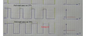
A sawtooth voltage generator (frequency 150 Hz) is implemented on transistor VT1 (unijunction). Operational amplifier DA1 plays the role of a comparator that creates PWM based on transistor VT2. The result is a PWM engine speed controller.
The rotation speed is changed by variable resistor R5, which changes the duration of the pulses. Since the amplitude of the PWM pulses is constant and equal to the supply voltage of the electric motor, it never stops even at a very low rotation speed.
Second scheme
It is similar to the previous one, but the operational amplifier DA1 (K140UD7) is used as the master oscillator.
This op-amp functions as a voltage generator producing triangular-shaped pulses and having a frequency of 500 Hz. Variable resistor R7 sets the rotation speed of the electric motor.
Third scheme
It is unique, built on the popular NE555 timer. The master oscillator operates with a frequency of 500 Hz. The pulse width, and therefore the engine speed, can be changed from 2% to 98%.
The weak point in all the above schemes is that they do not have an element for stabilizing the rotation speed when the load on the DC motor shaft increases or decreases. You can resolve this problem using the following diagram:
Like most similar regulators, the circuit of this regulator has a master voltage generator that produces triangular pulses with a frequency of 2 kHz. The entire specificity of the circuit is the presence of positive feedback (POS) through elements R12, R11, VD1, C2, DA1.4, which stabilizes the rotation speed of the electric motor shaft when the load increases or decreases.
When setting up a circuit with a specific motor, resistance R12, choose a PIC depth at which self-oscillations of the rotation speed do not occur when the load changes.
Technical parameters of the electric motor speed controller:
- Supply voltage: 230 V AC
- adjustment range: 5..99%
- load voltage: 230 V / 12 A (2.5 kW with radiator)
- maximum power without radiator 300 W
- low noise level
- speed stabilization
- soft start
- board size 50×60 mm
Schematic diagram
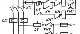
The control system module circuit is based on a PWM pulse generator and a motor control triac - a traditional circuit design for similar devices.
Elements D1, R1 limit the supply voltage to safe values for powering the generator microcircuit.
Capacitor C1 is responsible for filtering the supply voltage.
Elements R3, R5 and P1 are an adjustable voltage divider, which is used to set the amount of power supplied to the load.
Thanks to the use of resistor R2, which is directly included in the input circuit to the m/s phase, the internal units are synchronized with the VT139 triac.
The figure below shows the location of the elements on the printed circuit board. During installation and startup, attention should be paid to ensuring safe operating conditions (the regulator is powered by a 220V network and its elements are directly connected to the phase).
A similar engine speed controller can be bought in China with free shipping for only $1.5 (120 rubles) - Link
Increasing regulator power
In the test version, a BT138/800 triac with a maximum current of 12 A was used, which allows control of a load of more than 2 kW. If you need to control large load currents, we recommend installing the thyristor outside the board on a large radiator. You should also remember to select the correct FUSE fuse depending on the load.
Also, in addition to controlling the speed of electric motors, it is possible, without any modifications, to use a circuit to regulate the brightness of lighting lamps.
Parts of electric motor rotation controllers
In these circuits, it is possible to use the following replacements of radio components: transistor KT817B - KT815, KT805; KT117A can be replaced with KT117B-G or 2N2646; Operational amplifier K140UD7 on K140UD6, KR544UD1, TL071, TL081; timer NE555 - S555, KR1006VI1; microcircuit TL074 - TL064, TL084, LM324.
When using a more powerful load, the KT817 key transistor can be replaced with a powerful field-effect transistor, for example, IRF3905 or similar.
Source
Possibilities of “weak” currents
Various children's games, robotics, and home automation use low-power motors that operate from 12-volt power supplies. The rotation speed in such devices can be adjusted by connecting a resistor in series in the circuit. But at the same time, low efficiency is achieved, and there is no possibility to smoothly change the rotation speed. Sometimes, when the voltage is low, the motor may stop completely.
A 12V speed controller made by yourself will fully comply with the necessary characteristics, although it includes a minimum of elements: a transistor, an operational amplifier, a timer and a microcircuit.
Note!
DIY furniture made from pallets (140 photos) - step-by-step master class with diagrams and drawings, design ideas
DIY coffee table - manufacturing guide with a full description of the steps, choice of materials (120 photo ideas)
Do-it-yourself laundry basket (130 photo ideas): step-by-step master class for making it yourself, choice of materials, design options
If you plan to use stronger loads, you can take a more powerful field-effect transistor or assemble more complex systems that have increased control accuracy (with a timer).
Various circuit options allow you to create not only single-channel, but also dual-channel regulators.
Adjustment of electric motor speed 220V, 12V and 24V
To smoothly increase and decrease the shaft rotation speed, there is a special device - a 220V electric motor speed controller. Stable operation, no voltage interruptions, long service life - the advantages of using an engine speed controller for 220, 12 and 24 volts.
The methods for changing rotation depend on the model of the electric machine. The characteristics of electrical machines are different: direct and alternating current, single-phase, three-phase. Therefore, we need to talk about each case separately.
The simplest option
The easiest way is to change the speed of a DC motor. They can be changed by simply changing the supply voltage. And it doesn’t matter where: at anchor or excited, but this only applies to low-power machines with minimal load. Basically, the rotation speed is controlled via the armature circuit. Moreover, rheostatic regulation is possible here if the motor power is small, or there is a fairly powerful rheostat.
This is the most uneconomical option. The mechanical characteristics of a motor with independent excitation are the most unfavorable due to large losses, which results in a drop in mechanical power and efficiency.
Another possibility is to introduce a rheostat into the field winding. Considering the characteristics of an engine with independent excitation, we will see that regulation of the rotation speed is possible only in the direction of increasing revolutions. This occurs due to winding saturation.
So, rheostat control of the rotation speed of an independent excitation apparatus is justified in systems with minimal load. It is best when the work with this switching on is periodic.
In the anchor chain
This is the best option for regulating the speed of a motor with independent excitation. The rotation speed is directly proportional to the voltage supplied to the armature. The mechanical characteristics do not change their angle of inclination, but move parallel to each other.
To implement this scheme, you need to connect the armature circuit to a voltage source that can be changed.
This is possible in low or medium power electric machines. It is advisable to connect a high-power motor to a circuit with an independent excitation voltage generator.
A conventional three-phase asynchronous machine is used as a drive for the generator. To reduce the speed, it is enough to lower the voltage at the armature. It varies from nominal and down. This circuit is called “motor-generator”. This way you can change the parameters on a 220V engine.
For low voltage
Controlling 12V units is easier due to the lower voltage and, as a result, more accessible parts. There are many options for such schemes, so it is important to understand the principle itself.
Such a motor has a rotor, a brush mechanism and magnets. It has only two wires at the output; speed is controlled through them. The power supply can be 12, 24, 36V, or other. What is needed is to change it. It's better when it ranges from zero to maximum. In simpler options, 12–0V will not work; other options provide this opportunity.
From the network
Single-phase AC motors also allow you to control the rotation of the rotor.
Collector machines
Such motors are found on electric drills, jigsaws and other tools. To reduce or increase the speed, it is enough, as in previous cases, to change the supply voltage. There are also solutions for this purpose.
The structure connects directly to the network. The adjusting element is a triac, which is controlled by a dinistor. The triac is placed on the heat sink, the maximum load power is 600 W.
If there is a suitable LATR, you can do all this using it.
Two phase motor
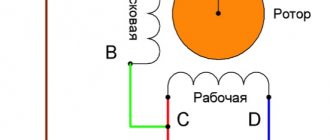
The device, which has two windings - starting and working, is two-phase in principle. Unlike three-phase, it has the ability to change the rotor speed. The characteristic of its rotating magnetic field is not circular, but elliptical, which is due to its design.
There are two possibilities for controlling the speed:
- Change the amplitude of the supply voltage (Uy),
- Phase - change the capacitance of the capacitor.
Such units are widely used in everyday life and in production.
Regular asynchronous
Three-phase electric machines, despite their ease of operation, have a number of characteristics that need to be taken into account. If you simply change the supply voltage, the torque will change within a small range, but no more. In order to regulate speed within a wide range, you need quite complex equipment, which is difficult and expensive to simply assemble and set up.
For this purpose, the industry has launched the production of frequency converters that help change the speed of the electric motor in the desired range.
The asynchronous machine gains momentum in accordance with the parameters set on the frequency driver, which can be changed in a wide range. The converter is the best solution for such engines.
Do-it-yourself electrics
Adjusting the speed of an electric motor is often necessary both for industrial and some domestic purposes. In the first case, industrial voltage regulators - inverter frequency converters - are used to reduce or increase the rotation speed. Let’s try to understand in more detail the question of how to regulate the speed of an electric motor at home.
It must be said right away that different power regulators should be used for different types of single-phase and three-phase electrical machines. Those. For asynchronous machines, the use of thyristor regulators, which are the main ones for changing the rotation of commutator motors, is unacceptable.
The best way to reduce the speed of your device is not by adjusting the speed of the engine itself, but through a gearbox or belt drive. At the same time, the most important thing will be preserved - the power of the device.
Selecting a device
In order to select an effective regulator, it is necessary to take into account the characteristics of the device and its intended purpose.
- Vector controllers are common for commutator motors, but scalar controllers are more reliable.
- An important selection criterion is power. It must correspond to that permitted on the unit used. It is better to exceed for safe operation of the system.
- The voltage must be within acceptable wide ranges.
- The main purpose of the regulator is to convert frequency, so this aspect must be selected according to the technical requirements.
- You also need to pay attention to the service life, dimensions, number of inputs.
Triac device
The triac device is used to control lighting, power of heating elements, and rotation speed.
The controller circuit based on a triac contains a minimum of parts shown in the figure, where C1 is a capacitor, R1 is the first resistor, R2 is the second resistor.
Using a converter, power is regulated by changing the time of an open triac. If it is closed, the capacitor is charged by the load and resistors. One resistor controls the amount of current, and the second regulates the charging rate.
When the capacitor reaches the maximum voltage threshold of 12V or 24V, the switch is activated. The triac goes into the open state. When the mains voltage passes through zero, the triac is locked, and then the capacitor gives a negative charge.
Converters on electronic keys
Thyristor power regulators are one of the most common, having a simple operating circuit.
Thyristor, works in alternating current network.
A separate type is the AC voltage stabilizer. The stabilizer contains a transformer with numerous windings.
DC stabilizer circuit
24 volt thyristor charger
The principle of operation is to charge a capacitor and a locked thyristor, and when the capacitor reaches voltage, the thyristor sends current to the load.
Proportional Signal Process
Signals arriving at the system input form feedback. Let's take a closer look using a microcircuit.
Chip TDA 1085
The TDA 1085 chip pictured above provides feedback control of a 12V, 24V motor without loss of power. It is mandatory to contain a tachometer, which provides feedback from the engine to the control board. The stabilization sensor signal goes to a microcircuit, which transmits the task to the power elements - to add voltage to the motor. When the shaft is loaded, the board increases the voltage and the power increases. By releasing the shaft, the tension decreases. The revolutions will be constant, but the power torque will not change. The frequency is controlled over a wide range. Such a 12, 24 volt motor is installed in washing machines.
With your own hands you can make a device for a grinder, wood lathe, sharpener, concrete mixer, straw cutter, lawn mower, wood splitter and much more.
Industrial regulators, consisting of 12, 24 volt controllers, are filled with resin and therefore cannot be repaired. Therefore, a 12V device is often made independently. A simple option using the U2008B chip. The controller uses current feedback or soft start. If the latter is used, elements C1, R4 are required, jumper X1 is not needed, but with feedback, vice versa.
DC Motor Speed Control
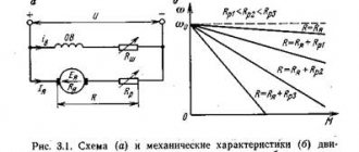
From the point of view of regulating the rotation speed of electric motors, the equation for electromechanical characteristics corresponding to Kirchhoff’s Second Law is interesting:
ω = U/C×Φ – ΥЯ /( C×Φ) 3 ×M
When describing the technical characteristics of an electric motor, the speed expressed in revolutions per minute is often called the rotational speed ν according to the well-known relationship:
ω = 2p/T = 2pn
Therefore, these two different quantities are often used in the same sense. The speed w (frequency ν ) is directly dependent on the supply voltage U and inversely dependent on the magnetic flux Ф. Based on the above formula, the conclusion arises that the speed can be controlled by adjusting the armature resistance, magnetic flux and supply voltage.
Adjustment methods
So, there are three main options for speed control:
- Changing the mains voltage . By changing the supplied power, you can control the engine speed;
- By adding a starting rheostat to the armature circuit . By adjusting the resistance, you can reduce the rotation speed;
- Magnetic flux control . Motors with electromagnets make it possible to regulate the flux by changing the excitation current. However, the lower limit ν min is limited by the saturation of the motor magnetic circuit, which does not allow the magnetic flux to be increased to a large extent.
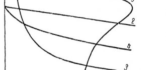
Each option corresponds to a certain dependence of mechanical characteristics.
Control methods apply to engines with various:
- types of excitation;
- the amount of power.
In practice, in modern electric motors, due to the disadvantages and limited ranges, the methods discussed are not always used.
This is also due to the fact that the machines are characterized by rather low efficiency, and also do not allow smoothly increasing or decreasing the rotation speed.
Electronic control circuits with frequency regulators powered by a 12 V battery, on the other hand, are widely used. For example, they are very relevant for controlling low-voltage 12-volt electric motors in automation devices, children's toys, electric bicycles, and battery-powered children's cars.
The fundamental feature of the method is that the current in the armature circuit and the torque developed by the electric motor depend only on the magnitude of the load on its shaft. Adjustment is carried out using the electric motor speed controller.
For a very long time, thyristor converters were the only commercially available motor controllers. By the way, they are still the most common today. However, with the advent of power transistors, DC motor speed controllers with pulse width modulation have become the most popular. For example, let's look at a circuit running from a 12 V DC source below.
In practice, the circuit makes it possible, for example, to increase or decrease the brightness of incandescent lamps by 12 volts.
Series-parallel control is used in situations where two or more DC units are mechanically connected. A series connection of electric motors, in which the total voltage is divided among all, is used for low speed applications. A parallel connection of machines having the same voltage is used in high speed applications.
Frequency regulation
Just recently (10 years ago), there were a limited number of frequency controllers for motor speeds on the market, and they were quite expensive. The reason was that there were no cheap high-voltage power transistors and modules.
But developments in the field of solid-state electronics have made it possible to bring power IGBT modules to the market. As a consequence, there is a massive appearance on the market of inverter air conditioners, welding inverters, and frequency converters.
At the moment, frequency conversion is the main way to regulate the power, performance, speed of all devices and mechanisms driven by an electric motor.
However, frequency converters are designed to control three-phase electric motors.
Single-phase motors can be controlled by:
- specialized single-phase inverters
- three-phase inverters with the exception of the capacitor
Converters for single-phase motors
Currently, only one manufacturer announces serial production of a specialized inverter for capacitor motors - INVERTEK DRIVES.
Optidrive E2 model
For stable engine starting and operation, special algorithms are used.
In this case, frequency adjustment is possible upward, but in a limited frequency range, this is prevented by a capacitor installed in the phase-shifting winding circuit, since its resistance directly depends on the frequency of the current:
f - current frequency
C - capacitance of the capacitor
The output stage uses a bridge circuit with four output IGBT transistors:
Optidrive E2 allows you to control the motor without removing the capacitor from the circuit, that is, without changing the motor design - in some models this is quite difficult to do.
Advantages of a specialized frequency converter:
- intelligent motor control
- Stably stable engine operation
- the enormous capabilities of modern inverters: the ability to control the operation of the motor to maintain certain characteristics (water pressure, air flow, speed under changing load)
- numerous protections (motor and device itself)
- sensor inputs (digital and analogue)
- various outputs
- communication interface (for control, monitoring)
- preset speeds
- PID controller
Disadvantages of using a single-phase inverter:
- limited frequency control
- high price
Reversing DC motors
The easiest way to reverse a DC motor is that it has a permanent magnet stator. It is enough to change the polarity of the power supply so that the rotor begins to rotate in the opposite direction.
It is more difficult to reverse a motor with electromagnetic excitation (series, parallel). If you simply change the polarity of the supply voltage, the direction of rotation of the rotor will not change. To change the direction of rotation, it is enough to change the polarity only in the field winding or only on the rotor brushes.
To reverse high-power motors, the polarity should be changed at the armature. A break in the field winding while the motor is running can lead to a malfunction, because the resulting EMF has an increased voltage, which can damage the insulation of the windings. Which will lead to failure of the electric motor.
To reverse the direction of rotation of the rotor, bridge circuits using relays, contactors or transistors are used. In the latter case, you can also regulate the rotation speed.
The figure shows a circuit using transistors. To illustrate the operation, the transistors are replaced by switch contacts. Similarly, bridge circuits are made not on bipolar, but on field-effect transistors.
The efficiency of such a circuit is much higher than that of transistors. Control is carried out by a microcontroller or simple logic circuits that prevent simultaneous signaling.
PWM DC motor speed controller
Let's combine the two circuits presented above, and we get a simple DC motor speed controller circuit, which can be used to control the engine speed of a toy, robot, micro drill, etc.
VT1 is an n-type field-effect transistor capable of withstanding the maximum motor current at a given voltage and shaft load. VCC1 is from 5 to 16 V, VCC2 is greater than or equal to VCC1.
Instead of a field-effect transistor, you can use a bipolar npn transistor, a Darlington transistor, or an opto-relay of appropriate power.
Source
Connection diagram for a commutator motor with reverse
To reverse a commutator motor, you need to know:
- Not every commutator motor can be reversed. If a rotation arrow is indicated on the housing, then it cannot be used in reversible devices.
- All high speed engines are designed to rotate in one direction. For example, in an electric motor installed in angle grinders.
- For an engine that has low speeds, rotation can occur in different directions. Such motors are mounted in power tools, for example, electric drills, screwdrivers, washing machines, etc.
The figure shows a diagram of a universal commutator motor, which can operate on both direct and alternating current.
To change the rotation of the rotor, it is enough to change the polarity of the voltage on the rotor or stator winding, as in DC motors, from which universal machines are practically no different.
If you simply change the polarity of the supply voltage to the commutator motor, the direction of rotation of the rotor will not change. This must be taken into account when connecting the electric motor to the network.
You should also know that in high-power motors the armature winding is switched. When switching the stator windings, a self-induction voltage arises, which reaches values that can damage the motor.
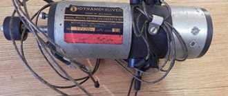
Amateur designers use various types of engines in their crafts. They often use a brush motor from an automatic washing machine. These are convenient motors that can be connected directly to a 220 volt network. They do not require additional capacitors, and the speed can be easily adjusted using a standard dimmer. Six or seven pins are output to the terminal block.
Depends on engine type:
- Two go to the commutator brushes.
- A pair of wires come from the tachometer to the block.
- The field windings may have two or three wires. The third is used to change the rotation speed.
To reverse the motor from a washing machine, you should swap the leads of the field winding. If there is a third output, then it is not used.
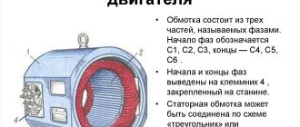
A little theory about the design and scope of commutator electric motors
Electric motors of this type can be direct or alternating current, with series, parallel or mixed excitation (for alternating current only the first two types of excitation are used).
A commutator motor consists of a rotor, stator, commutator and brushes. The current in the circuit passing through the stator and rotor windings connected in a certain way creates a magnetic field that causes the latter to rotate. Voltage is transmitted to the rotor using brushes made of a soft electrically conductive material, most often graphite or a copper-graphite mixture. If you change the direction of the current in the rotor or stator, the shaft will begin to rotate in the other direction, and this is always done with the rotor leads, so that the magnetization reversal of the cores does not occur.
If the connection of both the rotor and stator is changed simultaneously, reversal will not occur. There are also three-phase commutator motors, but that's a completely different story.
DC motors with parallel excitation
The field winding (stator) in a parallel-wound motor consists of a large number of turns of thin wire and is connected in parallel to the rotor, the winding resistance of which is much lower. Therefore, to reduce the current when starting electric motors with a power of more than 1 kW, a starting rheostat is included in the rotor circuit. The electric motor speed control with this connection scheme is carried out by changing the current only in the stator circuit, because The method of reducing the voltage at the terminals is very uneconomical and requires the use of a high-power regulator.
If the load is small, then if the stator winding accidentally breaks when using such a circuit, the rotation speed will exceed the maximum permissible and the electric motor may go into overdrive.
Series-wound DC motors
The field winding of such an electric motor has a small number of turns of thick wire, and when it is connected in series to the armature circuit, the current in the entire circuit will be the same. Electric motors of this type are more durable under overloads and therefore are most often found in household devices.