One of the main components of a truly high-quality seam is the correct and precise adjustment of the welding current in accordance with the task at hand. Experienced welders often have to work with metal of different thicknesses, and sometimes the standard min/max adjustment is not enough for proper work. In such cases, there is a need for multi-stage current regulation, accurate to the nearest ampere. This problem can be easily solved by connecting an additional device to the circuit - a current regulator.
The current can be adjusted in the secondary (secondary winding) and in the primary (primary winding). Moreover, each method of setting up a transformer for welding has its own characteristics that are important to consider. In this article we will tell you how to regulate the current in welding machines, provide diagrams of regulators for a semi-automatic welding machine, and help you choose the right welding current regulator for the primary winding for a welding transformer.
Methods for adjusting current
There are many ways to regulate the current, and above we wrote about the secondary and primary windings. In fact, this is a very rough classification, since the adjustment is still divided into several components. We will not be able to analyze all the components within the framework of this article, so we will focus on the most popular ones.
One of the most commonly used current control methods is to add a ballast at the output of the secondary winding. This is a reliable and durable method; you can easily make a ballast with your own hands and use it without additional equipment. Often, ballasts are used solely to reduce current.
In this article, we described in detail the operating principle and features of using a ballast for a semi-automatic welding machine. There you will find detailed instructions on how to make the device at home and how to use it in your work.
Despite many advantages, the method of adjusting the current through the secondary winding when used in conjunction with a welding transformer may not be very convenient, especially for novice welders. First of all, the ballast is quite bulky and its size can reach a meter in length. The device is also often underfoot and gets very hot, and this is a gross violation of safety regulations.
If you are not ready to put up with these shortcomings, then we recommend that you pay attention to the method when the welding current is adjusted through the primary winding. For these purposes, electronic devices that can be easily made with your own hands are often used. Such a device will easily regulate the current through the primary and will not cause inconvenience to the welder during operation.
The electronic regulator will become an indispensable assistant for a summer resident who is forced to weld under conditions of unstable voltage. Often houses are simply not allowed to use electrical appliances larger than 3-5 kW, and this is very limiting in their work. Using the regulator, you can configure your device so that it can operate smoothly even with low voltage. Also, such a device will be useful for craftsmen who need to constantly move from place to place while working. After all, the regulator does not need to be dragged around like a ballast, and it will never cause injury.
Now we will talk about how to make an electronic regulator from thyristors yourself.
General concepts
The principle of arc welding is well known. Let's refresh our memory of the basic concepts. To obtain a welding joint, an arc must be created. An electric arc occurs when voltage is applied between the welding electrode and the surface of the material being welded. The arc current melts the metal, forming a molten pool between the two ends. After the seam has cooled, we obtain a strong connection between the two metals.
Arc welding diagram.
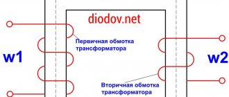
In Russia, alternating current is regulated at a frequency of 50 Hz. Power for the welding machine is supplied from the mains with a phase voltage of 220 V. Welding transformers have two windings: primary and secondary. The secondary voltage of the transformer is 70 V.
Separate manual and automatic welding modes. In a home workshop, welding is carried out manually. We list the parameters that can be changed manually:
- welding current;
- arc voltage;
- welding electrode speed;
- number of passes per seam;
- diameter and brand of electrode.
The correct selection and maintenance of the necessary parameters throughout the welding process are the key to a high-quality welded joint..
When carrying out manual arc welding, it is necessary to correctly distribute the current. This will allow you to make a high-quality seam. The stability of the arc directly depends on the magnitude of the welding current. Experts select it based on the diameter of the electrodes and the thickness of the materials being welded.
Thyristor regulator circuit
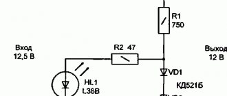
Above you can see a diagram of a simple regulator using 2 thyristors with a minimum of non-scarce parts. You can also make a regulator using a triac, but our practice has shown that a thyristor power regulator is more durable and operates more stably. The assembly diagram is very simple and according to it you can quickly assemble the regulator with minimal soldering skills.
The operating principle of this regulator is also simple. We have a primary winding circuit into which the regulator is connected. The regulator consists of transistors VS1 and VS2 (for each half-wave). The RC circuit determines the moment when the thyristors open, and at the same time the resistance R7 changes. As a result, we get the opportunity to change the current in the primary of the transformer, after which the current changes in the secondary.
Note! The regulator is adjusted under voltage, do not forget about this. To avoid fatal mistakes and avoid injury, it is necessary to isolate all radio elements.
In principle, you can use old-style transistors. This is a great way to save money, since these transistors can easily be found in an old radio or at a flea market. But keep in mind that such transistors must be used at an operating voltage of at least 400 V. If you find it necessary, you can use dinistors instead of the transistors and resistors shown in the diagram. We did not use dinistors, since in this version they do not work very stably. In general, this thyristor-based welding current regulator circuit has proven itself well, and on its basis many regulators have been manufactured that operate stably and perform their function well.
You could also see in stores the resistance welding regulator RKS-801 and the resistance welding regulator RKS-15-1. We do not recommend making them yourself, since it will take a lot of time and will not save you much money, but if you want, you can make RKS-801. Below you see a diagram of the regulator and a diagram of its connection to the welder. Open the pictures in a new window to see the text better.
How to make a current regulator for a welding machine with your own hands
One of the main components of a truly high-quality seam is the correct and precise adjustment of the welding current in accordance with the task at hand. Experienced welders often have to work with metal of different thicknesses, and sometimes the standard min/max adjustment is not enough for proper work. In such cases, there is a need for multi-stage current regulation, accurate to the nearest ampere. This problem can be easily solved by connecting an additional device to the circuit - a current regulator.
The current can be adjusted in the secondary (secondary winding) and in the primary (primary winding). Moreover, each method of setting up a transformer for welding has its own characteristics that are important to consider. In this article we will tell you how to regulate the current in welding machines, provide diagrams of regulators for a semi-automatic welding machine, and help you choose the right welding current regulator for the primary winding for a welding transformer.
Welding current measurement
Once you have made and configured the regulator, it can be used in operation. To do this, you need another device that will measure the welding current. Unfortunately, it will not be possible to use household ammeters, since they are not capable of working with semi-automatic devices with a power of more than 200 amperes. Therefore, we recommend using a clamp meter. This is a relatively inexpensive and accurate way to find out the current value; the clamp control is clear and simple.
The so-called “clamps” at the top of the device grip the wire and measure the current. There is a current measurement limit switch on the device body. Depending on the model and price, different manufacturers make clamp meters capable of operating in the range of 100 to 500 amps. Choose a device whose characteristics match your welding machine.
Clamp meters are an excellent choice if you need to quickly measure current without interfering with the circuit or connecting additional elements to it. But there is one drawback: clamps are absolutely useless when measuring DC current values. The fact is that direct current does not create an alternating electromagnetic field, so the device simply does not see it. But when working with alternating current, such a device meets all expectations.
There is another way to measure current, it is more radical. You can add an industrial ammeter to the circuit of your semi-automatic welding machine, capable of measuring large current values. You can also simply temporarily add an ammeter to the open circuit of the welding wires. On the left you can see a diagram of such an ammeter, according to which you can assemble it.
This is a cheap and effective way to measure current, but using an ammeter in welding machines also has its own characteristics. It is not the ammeter itself that is added to the circuit, but its resistor or shunt, and the dial indicator must be connected in parallel to the resistor or shunt. If you do not follow this sequence, the device, at best, simply will not work.
Types of current regulators
Schematic diagram of a DC regulator.
There are more ways to change the current during welding operations. Even more electrical circuit diagrams of regulators have been developed. The methods for controlling the welding current can be the following:
- installation of passive elements in the secondary circuit;
- switching the number of turns of transformer windings;
- change in the magnetic flux of the transformer;
- adjustment on semiconductors.
You should know the advantages and disadvantages of different adjustment methods. Let us name the characteristic features of these types.
Resistor and choke
The first type of adjustment is considered the simplest. A resistor or inductor is connected in series to the welding circuit. In this case, the change in current and arc voltage occurs due to resistance and, accordingly, voltage drop. Craftsmen appreciated a simple and effective way to regulate the current - including a resistance in the secondary circuit. The device is simple and reliable.
Changing the current value using a resistor.
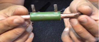
Additional resistors are used to soften the current-voltage characteristic of the power source. Resistance is made from thick (5-10 mm in diameter) nichrome wire. Powerful resistance wires are used as a passive element.
To regulate the current, a choke is installed instead of a resistance. Due to the introduction of inductance into the AC arc circuit, a phase shift of the current and voltage is observed. The current crosses zero occurs at a high transformer voltage, which increases the reliability of re-ignition and the stability of the arc. The welding mode becomes soft, resulting in a uniform and high-quality seam.
This method is widely used due to its reliability, ease of manufacture and low cost. The disadvantages include a small control range and difficulty in adjusting parameters. Anyone can make such a design. Transformers such as TS-180 or TS-250 are often used from old tube TVs, from which the primary and secondary windings are removed and a choke winding with the required cross-section is wound. The cross-section of the aluminum wire will be about 35-40 mm, copper - up to 25 mm. The number of turns will be in the range of 25-40 pieces.
Switching the number of windings
Voltage adjustment is carried out by changing the number of turns of the winding. This is how the transformation ratio changes. The welding current regulator is easy to operate. For this method of adjustment, it is necessary to make bends during winding. Switching is carried out by a switch that can withstand high current and mains voltage. Disadvantages of switching turns: it is difficult to find a switch that can withstand a load of a couple of hundred amperes, a small current adjustment range.
Simple design of DC welding machine
Based on the installation principle, the following parts can be distinguished:
- homemade transformer for welding;
- its power supply circuit is from network 220;
- output welding hoses;
- power unit of a thyristor current regulator with an electronic control circuit from a pulse winding.
Pulse winding III is located in power zone II and is connected through capacitor C. The amplitude and duration of the pulses depend on the ratio of the number of turns in the capacitor.
Radio circuits. — Welding machine with electronic current control
categorydo-it-yourself welding and welding equipmentmaterials in the category
Many metal structures are assembled using electric welding. I made several devices for this, and one turned out to be the most successful and easy to use. I bring to your attention a welding transformer with electronic current control. It has no moving parts that require high quality assembly and are subject to vibration. The control unit allows you to smoothly regulate the welding current by turning the potentiometer knob. At the same time, the arc burns stably throughout the entire range of changes. I think this design should be of interest to the readers of the magazine.
| Technical characteristics of a welding transformer with electronic current regulation: | |
| Supply voltage, V | 220 |
| Welding current control limits, A | 45 — 140 |
| Power arc open circuit voltage, V | 42 |
| Pilot arc no-load voltage, V | 87 |
| Make-up current, A | 15 |
Figure 1 shows the electrical circuit of the welding machine. It includes: welding transformer T3; power rectifier using thyristors VS3, VS4; rectifier for powering the pilot arc using diodes VD6 - VD9, smoothing choke L1; control unit for power thyristors on transistors VT1 - VT5.
Welding machine diagram
The main arc is powered by a rectifier using thyristors VS3, VS4; the value of the welding current changes by changing the switching angle of the thyristors.
When the power thyristors are closed, the welding arc current is provided by the feed circuit on diodes VD6 - VD9 and inductor L1.
The power rectifier has a falling external characteristic. The pilot arc rectifier has a steep external characteristic, and due to the inductor L1, a continuous current is maintained in the arc circuit, which ensures stable arc burning and prevents shedding of the electrode coating.
The control circuit consists of a power source on transformer T1, a rectifier on diodes VD1, a synchronization circuit on transistors VT1 and VT5, a phase-shifting device on transistors VT3, VT4, a comparison unit on transistor VT2, a welding current meter circuit on current transformer T4, a control circuit for power thyristors on thyristors VS1 and VS2.
The synchronization circuit on transistors VT1, VT5 is designed to discharge capacitance C3 of the phase-shifting device at the beginning of each half-cycle of the network supply voltage. At the moment when the network voltage is 0, at the base of the transistor VT1 there will be 0 (it is closed), and VT5 is open and C3 is discharged; in all other cases, VT5 is closed.
At the beginning of each half-cycle of the supply voltage, capacitor C3 is charged through VT2 and R8; at the moment when the voltage at C3 is equal to the voltage at the base of the transistor VT3, it opens, VT4 and C3 are discharged to the I winding of the pulse transformer T2. From windings II and III, a current pulse opens the thyristor VS1 or VS2 (the thyristor opens, at the anode of which there is a positive half-wave voltage). The control current from winding III or IV of transformer T1 through an open thyristor VS1 or VS2 is supplied to the power thyristor VS3 or VS4. Of these thyristors, the one through whose control electrode the control current flows opens. The latter is limited by resistors R14 or R15. The welding arc current flows through the open thyristor VS3 (VS4), it is measured by current transformer T4 and through the feedback circuit VD5, R17, C4, R18, R20, R7 is supplied to the comparison circuit on transistor VT2. The voltage from the resistor R20 motor is compared with the voltage at point “A” of the comparison circuit. Transistor VT2 changes its internal resistance (it operates in active mode) depending on the voltage difference at point “A” and across the resistor R20. If the current through the welding arc has increased more than that set by the control unit, the internal resistance VT2 increases, capacitor C1 charges more slowly, the switching angle of the power thyristors increases and, therefore, the current through the welding arc decreases.
If the welding current decreases below that set by the control unit, reverse processes occur: the switching angle of the power thyristors decreases and, consequently, the arc current increases. In this way, the welding current is regulated.
The welding arc current is set from the control panel by turning the resistor R20 slider. As the arc burns, the gap between the end of the electrode and the welding product changes, therefore, the voltage on the arc also changes. In some cases (with a large gap) it becomes greater than the open circuit voltage of the power rectifier, and then the arc begins to be powered by the pilot arc rectifier, and the power thyristors close. If the length of the welding arc decreases, the power thyristors will open again, since control current flows through the control electrode of the thyristor during the entire half-cycle.
Transformer T1 can be of any power, but not less than 20 W, primary winding I - 220 volts, winding II - 24 volts, wire diameter not less than 0.13 mm, windings III and IV - 12 volts, wire diameter not less than 0.25 mm.
Transformer T2 is wound on a K20x10x5 core made of 2000NM ferrite. Its windings I, II, III are each 50 turns of PEV-1 wire with a diameter of 0.2 mm.
The core of the T3 transformer is made of electrical cold-rolled steel grade 3404 with a thickness of 0.35 mm (dimensions are shown in Fig. 2). Winding I - 162 turns: two sections of 81 turns of copper wire with a cross section of 8 mm2 (2x4 mm). Each winding II and III has 32 turns: it consists of two sections of 16 turns of copper wire with a cross-section of 15 mm2 (3×5 mm). Windings I, II, III have fiberglass insulation impregnated with heat-resistant varnish. Winding IV, V - 93 turns of enameled wire with a diameter of 1.7 mm.
Welding transformer design
1 — winding I (two sections of 81 turns of copper wire with a cross-section of 8 mm2); 2.3 - windings II and III (each of two sections of 16 turns of copper wire with a cross-section of 15 mm2); 4.7 - windings V and IV (93 turns of enameled wire with a diameter of 1.7); 5 - core (cold-rolled steel grade 3404, sheet s0.35); 6 - magnetic shunt.
As a current transformer T4, a core from a current transformer TK 200, 100/5 was taken. It has two primary
windings of one turn with a cross section of 15 mm2. As a wire, you can use a welding cable or other stranded wire in insulation. The secondary winding is 400 turns of enamel wire with a diameter of 0.5 mm. It is wound onto the frame from the old secondary winding.
Debugging of the welding transformer is carried out block by block. First, it is assembled and connected to the network through a fuse of at least 30 A. Then the voltage on the secondary windings is checked: on II and III - up to 45 volts, and they must be turned on according to; on windings IV and V - up to 90 volts (switching on is also according to). The single-turn windings of current transformer T4 are connected in series with the power thyristors so that it operates in magnetization reversal mode.
After assembling the control unit, check the pulses at the T2 output and the operation of the synchronization circuit. For ease of testing, instead of transistor VT2 in parallel with R9, you should install a variable resistance of 20 kOhm and, by changing its value, check the change in the switching angle of the dinistor analogue. Then the whole circuit is assembled. An ammeter with a total deflection current of 150 - 200 A is placed in the welding arc circuit. When welding metal, it is necessary to adjust the resistor R18 so that when the handle of the variable resistor R20 is turned, the welding current changes from 45 to 140 A.
Power thyristors are mounted on standard radiators; diodes VD6 - VD9 are installed on four radiators with an area of 30 cm2 each.
The welding transformer has been successfully and reliably operated since 1993 to this day; electronic control of the welding current is very convenient during welding work, especially in different spatial positions of the welding seam.
N. ZYZLAEV, SamaraModel designer 2005 No. 1
Literature:
1. D. Priymak. To help the radio circle - Radio. 1989. No. 5. With. 79.2. M.I. Zaks, B.A. Kagansky, A.A. Pechenin. Transformers for electric arc welding. Leningrad: Energoatomizdat. 1988
3. V.M. Rybakov. Arc and gas welding. - Moscow: “Higher School”, 1986
Throttle core L1 is made of electrical steel; the cross-section of the magnetic core (passing through the winding) is at least 12 cm2 with a non-magnetic gap of 1 mm. The number of turns of enamel wire with a diameter of 2.24 mm is 68.
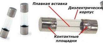
The electronic circuit is not critical to radio elements, with the exception of VTZ and VT4 (a pair of these transistors should be an analogue of a dinistor). Resistor R20 must have a knob to regulate the welding current. Resistor R16 is PEV 10. Resistor R15 (R14) is assembled from three parallel-connected one-watt resistors of 47 Ohms each.
radio-uchebnik.ru
Setting methods
There are various methods for adjusting the voltage, we previously talked about the energy of the converted AC and the converted.
In reality, this is too broad a division, because the setting still has subtypes. We will not be able to talk in detail about the subspecies in this article, so we will discuss the more popular ones.
The main method of setting the current regulator for a welding machine is to add a ballast at the energy output of the converted alternating current.
This method is considered safe and durable; it is easy to make a ballast yourself and use it for work without auxiliary equipment. Basically, the ballast is used only to reduce voltage.
We have already talked in detail about the intricacies of work and the use of a ballast for a semi-automatic inverter. There are important recommendations on how to make an electrical appliance at home and how to use it for work.
In addition to the advantages, a method of adjusting the energy of the converted alternating current, used in conjunction with an energy converter. It may not be so convenient for cooking, especially for inexperienced craftsmen.
Firstly, the ballast is of a sufficiently large size - up to 1 m long. Basically, such an electrical device is placed underfoot; it can become very hot, which violates safety rules.
If you are not satisfied with such qualities, then it is better to choose a method that includes adjusting the cooking voltage according to the energy of the converted alternating current.
For this, an electric current regulator for a welding machine is often used, which is easy to make yourself. Such a device is easy to adjust according to the energy of the converted alternating current and will be convenient for the master to work with.
An electric current regulator for a welding machine will be the first assistant in working in the country, where the power supply is often intermittent.
It happens that in houses it is impossible to use electrical appliances larger than 4 kW, which makes the work limited.
With an adjustment device, it is possible to adjust the device so that it will work non-stop in the absence of decent voltage.
Another advantage of the current regulator for the welding machine is that it is easy to work with when you need to frequently change the place to do the work. There is no need to take the regulator device with you, like a ballast, it will not injure you.
Let's talk about making your own electrical control device from thyristors.
↑ Design and details
In my version, the rectifier with regulator is made as a separate unit and is connected to the welding machine with flexible jumpers approximately 0.5 m long. This is more convenient, since there is no need to redo a ready-made welding machine; moreover, you can weld with both direct and alternating current. With this design, the rectifier unit can be connected to any welding transformer. Diodes and thyristors are installed on separate finned radiators (Fig. 2).
All connecting jumpers are made of stranded copper wire with contact terminals at the ends for bolted connections. The electronic control circuit is made on a printed circuit board (Fig. 3), although the volumetric installation, assembled with high quality, is no worse.
View from the parts
Pulse transformer T2 - grade TI-3; TI-4; TI-5, with a transformation ratio of 1:1:1. You can wind it yourself on a ferrite ring, for example, 32x20x6 MH2000. All windings contain 100...150 turns of copper winding wire of the PEV, PELSHO brand 0.25...0.3 mm. Before winding, the core must be wrapped with a layer of varnished cloth. Capacitor C1 is made up of 4 capacitors of 15,000 μF each with an operating voltage of at least 80V. Since when the welding circuit is closed and opened and when the arc is burning, the feeding currents flowing through the capacitors are very large, it is necessary to connect the capacitors according to the “star” circuit (4 wires go from one connecting terminal to the “+” terminal of each capacitor, and from the second terminals - also 4 wires to the “-” terminal of the capacitors). The cross-section of each wire is chosen such that the total cross-section of all 4 wires is not less than the cross-section of the supply power cables.
If there is a shortage of capacitance of capacitor C1, 44,000 μF (two imported ones of 22,000 μF each at 90 V), during operation of the device, the capacitors heat up from increased currents (charge-discharge), with four imported ones of 22,000 μF each at 90 V, during very long operation in welding mode a little warm. Practice has shown that C1 works better with a larger number of capacitors of smaller capacity.
The inductor is wound on a core with an area of 20...30cm2, with a non-magnetic gap of 0.5...1 mm. The number of turns can be from 25 to 60...80. The more turns, the better, but heat dissipation from the inner layers of the winding worsens. The winding wire must have a cross-section no less than the cross-sectional area of the wire with which the secondary winding of the transformer is wound. This also applies to all jumpers that make connections to the power unit.
The welding current can reach 100...180A, depending on the power of the welding transformer. This must be taken into account during installation. When making a bolted connection, you must follow the rule: the welding current should not flow through the bolt, unless, of course, it is copper or brass. This mainly applies to the input and output terminals. One of the options for how to do this is shown in Fig. 4.
It is advisable to make the rectifier housing from a non-flammable material, but you can even make it from plywood if space allows and move away from heating radiators. Ventilation holes are required in the housing. The current control knob is installed on the body, and a scale with divisions is applied around it - for more convenient setting of the current. For the convenience of adjusting the working current, I installed a 110 incandescent control lamp at the minimum power according to the degree of which I was guided when setting the welding current. An automatic circuit breaker for the corresponding operating current is used as a fuse in the primary circuit of the transformer. A fan for forced cooling must be used with a fairly decent-sized impeller. All this creates conditions for safe, more reliable operation of the device.
PS I apologize for the low quality of the pictures. They were retaken with a phone (Nokia N73) from old inkjet printouts. There is no way to take new photos from the device since it has been sold.
