Repair of a tubular fuse, selection of wire diameter
In modern electrical appliances, fuses are found everywhere, or, to put it scientifically, fuses.
They protect the network and the device itself from short circuits or overload. The design of fuse links is very diverse, as are the sizes. The rated currents and voltages for which fuses are issued correspond to standard values. Its overall dimensions, namely length, depend on the rated voltage of the fuse; the higher the rated voltage of the fuse, the greater the distance between the contacts. The rated current is determined by the cross-section of the wire inside the fuse. Although self-resetting electrical fuses can now be found in more expensive devices, most devices are still equipped with conventional fuses.
General concepts, introduction to tubular fuses
The most common fuses are the so-called tubular ones. They are a ceramic or glass tube with metal cup contacts at the ends. These cups are connected to each other by wire, the cross-section of which, as already mentioned, determines the rated current of the fuse. This current is indicated on the tube or one of the contact parts of the fuse. For example: F0.5A - this means that this fuse is rated for a current of 0.5 amperes.
On electrical circuit diagrams, a fuse is indicated by a rectangle with a straight line passing through it. Next to the conventional graphic designation its position designation is indicated, for example F1 (F – fuse, fuse in English); and if this does not clutter the circuit - the rated current, for example 100 mA.
Description of the operating principle of a fuse link (fuse)
The principle of operation of the fuse is extremely simple. When a rated current flows through the wire connecting the fuse contacts, this wire heats up to a temperature of about 70 °C. But when the current is exceeded, the wire heats up more, and when the melting temperature is exceeded, it melts, i.e. burns out. It is for this reason that fuses are also called fuses or fusible links. The higher the current, the faster the heating, the faster the melting occurs, and, accordingly, the fuse blows.
Thus, all fuse links operate on the same principle - excess current in the circuit causes overheating and melting of the wire inside the fuse and, as a result, disconnection of this circuit from the power source.
There are two main reasons for the burnout of fuse links: surges in the supply voltage and a malfunction within the electrical appliance itself.
Fuses in household appliances
Special plugs are available with fuses located inside. The fuse may blow if there is a problem within the plug itself. The main cause is usually a short circuit. In order to replace it, you need to unscrew the top part of the plug and use a screwdriver to pull it out of the clamping plates. After that, it is checked by a tester. If you don’t have a tester, you can check by installing it in the plug of a working device. The blown fuse is replaced with another, serviceable one, having the appropriate characteristics.
Individual appliances can be connected directly to fuse blocks that are mounted on the wall. It is placed in a special secret cartridge. To remove it, you need to turn off the connecting block and use a screwdriver to remove it.
Checking the fuse, fuse fault indicator
You can check the fuse-link with any continuity tester or tester. The goal is to ensure that the fuse circuit is intact and capable of conducting electrical current.
To avoid electric shock, checking the fuse is only allowed when the electrical appliance is turned off!
In addition, you can buy or make your own fuse blown indicator, which will notify you that the fuse has blown.
The circuit diagram of such a device is extremely simple and is shown in the following figure.
LED HL1 is connected in parallel to the fuse contacts, through current-limiting resistor R1 and diode VD1, to protect against reverse voltage. Diode VD1 must be selected based on the reverse voltage exceeding the mains voltage. For a 220 V network, the reverse voltage for the VD1 diode must be at least 300 V; for example, the 1N4004 diode or the domestic KD109B meets these requirements.
The indicator does not light if the fuse is good, and lights up if it is blown.
The indicator does not light if the load is disconnected.
This circuit is very convenient to complement home-made power supplies.
By slightly changing (simplifying) the circuit, you can get a fuse blown indicator on a neon lamp, although it does not look as effective as an LED.
Replacing the fuse
When replacing a fuse, to avoid electric shock, be sure to unplug the electrical appliance!
There is an unspoken rule: if after the second replacement the fuse blows again, look for a fault in the electrical appliance itself. This means that the electrical appliance needs to be repaired.
Do not install a fuse at a higher current under any circumstances; such attempts will definitely lead to even greater damage to the device, up to the point of its being beyond repair!
Be careful when purchasing a new fuse. Correctly determine the type and current rating of the replacement candidate. It is better to purchase electronic components from trusted suppliers who guarantee product quality, such as Conrad Electronic. The full range of fuses can be found at the link - https://conrad.ru/catalog/predohraniteli_s_plavkoy_vstavkoy.
Replacement of fuses and fuses.
5. Electrical equipment of class 2. II - having double or reinforced insulation and not having elements for grounding. Designation: double square
EXAMINATION TICKET No. 11
Group: Electricians of the 3rd category for repair and maintenance of electrical equipment QUESTIONS
1. Installation of grounding in distribution devices. In electrical installations with voltages up to 1000 V, when working on the busbars of switchgear switchgears, switchboards, assemblies, the voltage from the busbars must be removed and the busbars (with the exception of busbars made with insulated wire) must be grounded. The need and possibility of grounding connections of these switchgears, switchboards, assemblies and equipment connected to them is determined by the issuing order or order. Temporary removal of grounding connections installed during preparation of the workplace is allowed if this is required by the nature of the work being performed (measuring insulation resistance, etc.). Temporary removal and reinstallation of groundings is carried out by operational personnel or on the instructions of the work contractor issuing the work order. Permission to temporarily remove groundings, as well as to perform these operations by the work contractor, must be included in the “Separate instructions” line of the work order. In electrical installations, the design of which is such that the installation of grounding is dangerous or impossible (for example, in some distribution boxes, switchgear of certain types, assemblies with a vertical phase arrangement), additional measures must be developed to ensure work safety, including the installation of dielectric caps on the disconnector blades, dielectric pads or disconnecting wires.
2. Potential equalization system. Additional potential equalization system. The main potential equalization system in electrical installations up to 1 kV should connect the following conductive parts (Fig. 1.7.7): 1) zero protective RE-
or
PEN
- supply line conductor in a
TN system;
2) a grounding conductor connected to the grounding device of the electrical installation in
IT
and
TT systems;
3) a grounding conductor connected to the re-grounding electrode at the entrance to the building (if there is a ground electrode);
4) metal pipes of communications entering the building: hot and cold water supply, sewerage, heating, gas supply, etc. If the gas supply pipeline has an insulating insert at the entrance to the building, only that part of the pipeline that is located relative to the insulating insert on the side of the building is connected to the main potential equalization system; 5) metal parts of the building frame; 6) metal parts of centralized ventilation and air conditioning systems. If there are decentralized ventilation and air conditioning systems, metal air ducts should be connected to the PE
of the power supply panels for fans and air conditioners;
Rice. 1.7.7. Potential equalization system in the building:
M -
open conductive part;
C1
- metal water pipes entering the building;
C2
- metal sewer pipes entering the building;
C3 -
metal gas supply pipes with an insulating insert at the inlet, entering the building;
C4 -
ventilation and air conditioning ducts;
C5
- heating system;
C6 -
metal water pipes in the bathroom;
C7 -
metal bath;
C8 -
third-party conductive part within reach of open conductive parts;
C9 -
reinforcement of reinforced concrete structures;
GZSh - main grounding bus; T1
- natural grounding conductor;
T2
— lightning protection grounding conductor (if available);
1 -
neutral protective conductor;
2
- conductor of the main potential equalization system;
3 -
conductor of the additional potential equalization system;
4 —
down conductor of the lightning protection system;
5
- circuit (main) of working grounding in the information computing equipment room;
6 -
working (functional) grounding conductor;
7 -
potential equalization conductor in the working (functional) grounding system;
8 -
grounding conductor
7) grounding device of the lightning protection system of the 2nd and 3rd categories;
 grounding conductor of functional (working) grounding, if there is one and there are no restrictions on connecting the working grounding network to the protective grounding device;
9) metal sheaths of telecommunication cables.
Conductive parts entering the building from the outside must be connected as close as possible to the point of their entry into the building.
To connect to the main potential equalization system, all specified parts must be connected to the main grounding bus ( see 1.7.119-1.7.120) using potential equalization system conductors.
1.7.83. The additional potential equalization system must connect with each other all simultaneously accessible open conductive parts of stationary electrical equipment and third-party conductive parts, including accessible metal parts of building structures, as well as neutral protective conductors in the TN
and protective earth conductors in
IT
and
TT systems,
including protective conductors for socket outlets.
For potential equalization, specially provided conductors or exposed and third-party conductive parts may be used if they satisfy the requirements of 1.7.122 for protective conductors with regard to conductivity and continuity of the electrical circuit.
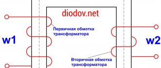
3.Residual current device (RCD). RCD - residual current device. The principle of its operation is based on Kirchhoff's rule (the sum of the currents is zero). The device monitors leakage currents that occur when a person touches a live wire, damage to the insulation, etc. The most common RCDs with a cutoff current of 10mA, 30mA and 300mA. In residential and public premises, as a rule, RCDs with a cut-off current of 30 mA are used. The main task of an RCD is to protect people from electric shock and fire. The device consists of 3 main functional units: A summing current transformer for detecting leakage current. Trip release. Switching device locking device with contacts. The summing current transformer is connected to all live wires and to the neutral wire. In an undamaged installation, the magnetizing effect of the current-carrying wires in the summing current transformer is mutually compensated, since, according to Kirchhoff's law, the sum of all currents is zero. Thus, there is no residual magnetic field that could induce voltage in the secondary winding. If, as a result of an insulation fault, a leakage current appears, then the above-mentioned equilibrium is disrupted and a residual magnetic field remains in the transformer core. As a result, a voltage arises in the secondary winding, which turns off the electrical circuit through the release and blocking device of the switching device. The devices are two-pole (single-phase network) and four-pole (three-phase network). The RCD is mounted on a DIN strip. When purchasing an RCD, you should focus on its operating current, which should cover the maximum load current, and the calculated leakage current, which was discussed above. The operating current of the RCD can be 16, 25, 40, 63, 80 A (depending on the manufacturer). The RCD must be protected from overload by a circuit breaker. For example, an RCD rated 25 A must be protected by a circuit breaker having an operating current < 25 A, i.e. 16 A (in fact, the selectivity condition is met).
⇐ Previous8Next ⇒
Recommended pages:
Fuse repair
Typical people believe that fuses cannot be repaired; in fact, this is not the case. Most types of fuses can be repaired and given a second, third, etc. life. The fuse housing, as a rule, is destroyed extremely rarely, the wire inside burns out, and the repair consists of replacing it. The main task is to use a wire similar to the one in the fuse.
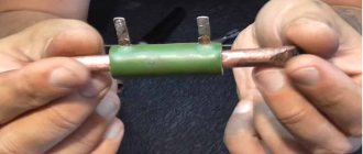
If you need to replace a fuse very quickly, but you don’t have a spare at hand, you can use the following method:
Remove the paint coating from a wire of a suitable diameter (clean it until it shines) and wind several turns around each fuse contact, then insert the fuse into the holder. This method is popularly called “bug”. With its help you can very quickly check the serviceability of the device, but it is not reliable and can be used as a temporary solution to the problem.
The next method is the so-called “factory” one. Repairs will require a soldering iron, and perhaps a Dremel or screwdriver, but the fuse after repair will look like it came straight from the factory.
Heat the ends of the cup contacts with a soldering iron and remove the solder from the holes in the ends using a toothpick or something similar. It happens that the holes are too small or completely absent, then you will have to drill them. Use a drill of small diameter 1 - 2 mm.
Pass a wire of a suitable diameter through the holes and solder it to the cup contacts.
Sequence of fuse repair
Repair of fuses with replaceable inserts consists of replacing them with new ones designed for the same current.
The rated current of the insert is indicated on its surface in those places that are not affected by melting. Additionally, the insertion current of the fuse is indicated next to it on the device body, and at industrial facilities a tag is additionally hung on the fuse body.
If cracks, soot, or metallization from the action of an electric arc appears on the body, it is replaced. Any defect that can impair the arc-extinguishing properties of the fuse will lead to problems when disconnecting the next short circuit: the body will melt, the arc will spread to adjacent contacts. The switchgear will switch off completely and be damaged.
The fuses in household equipment are replaced entirely. In plug-type fuses, the fuse link is replaced. But inserts for the required current are not always at hand. Sometimes it becomes necessary to temporarily repair a fuse, but at the same time ensure trouble-free operation of the protected device.
Electricians have long solved this problem by installing, instead of inserting, a thin copper wire called a “bug.” But when installing it, you need to take into account two main rules, compliance with which will preserve the safety of the repaired fuse:
- The wire must not be wound outside the housing. It should be in the same place where the burnt insert was. Otherwise, when melting, the “bug” will cause a fire or a large-scale short circuit.
This is how you can't do it:
To select the correct wire cross-section, use the table:
Selecting the diameter of the fuse wire
As written above, to repair a fuse, it is necessary to replace the burnt wire with one similar to the one that was in the fuse before it burned out.
Factory fuses use wires made of various metals: silver, copper, aluminum, tin, lead, nickel, etc. At home, it is unlikely that we will be able to determine the material of the wire of a blown fuse, and we also have ordinary copper wire at hand. But just in case, we present a table of wire diameters depending on the rated current of the fuse, containing, in addition to copper, aluminum, steel and tin.
How to repair a fuse.
In the industrial production of fuses, wires made of various materials are used (copper, aluminum, tin, lead, nickel, silver, etc.) - it all depends on the magnitude of the current and the requirements for the device’s response speed when the rating is exceeded.
When repairing an insert, only one option is possible - using red copper wire. Finding such a wire is not at all difficult - for sure, any master has small pieces of wire left over after laying or repairing electrical wiring.
The main task is to correctly determine the diameter of the wire based on the fuse rating. If this parameter cannot be determined from the element itself (for example, the number has become unreadable), the power of the device is taken as a basis. In this case, one important rule must be observed - the maximum permissible current of the insert must be greater than the current required by the device when operating in maximum mode. For example, if the product is designed for a maximum current of 1 ampere, then a protective element of 2 amperes is selected. Once you have decided on the fuse rating, you should select the wire diameter using the following data:
- for a fuse with a current of 0.25 A, a wire with a diameter of 0.02 mm is required;
- fuse 0.5 A – wire diameter 0.03 mm;
- 1 A – 0.05 mm;
- 2 A – 0.09 mm;
- 3 A – 0.11 mm;
- 5 A – 0.16 mm;
- 7 A – 0.20 mm;
- 10 A – 0.25 mm;
- 15 A – 0.33 mm;
- 20 A – 0.40 mm;
- 25 A – 0.46 mm;
- 30 A – 0.52 mm;
- 35 A – 0.58 mm;
- 40 A – 0.63 mm;
- 45 A – 0.68 mm;
- 50 A – 0.73 mm;
- 60 A – 0.83 mm;
- 70 A – 0.91 mm.
Homemade fuse
The fuse
in the electronic device has failed .
It is clear that you need to understand the reasons for the blown fuse and eliminate them. Let's say you did this, you need to turn on the device to check, but there is no intact fuse. The material of the article in an abbreviated form is duplicated in the video:
The fuse can be replaced with a piece of wire, the diameter of which depends on the amount of permissible current. Therefore, without much risk, you can replace a blown fuse with a copper wire inserted and soldered into the old fuse housing.
To determine the diameter of a copper wire, use the formula:
How many amps?
Fuses are designed to allow only a specified amount of current to pass through. Replace a blown fuse with a higher amp fuse at your own risk. You can cause a melt in the wiring harness - which in turn will cause several short circuits, some of which may not be protected by other fuses. You may have to replace the entire wiring harness, or it may result in an electrical fire that will completely destroy your vehicle.
LOCATE THE FUSE BLOCK. What fuse box? Many cars have more than one. Typically the main unit is located under the instrument panel. Look above the driver's feet (1), behind the inspection panel on the left side of the instrument panel, or near the bottom of the glove compartment. If you can't see it, then you need to refer to your owner's manual, which will tell you where to look for it. There should be a diagram on the fuse box cover (2).
There may be an additional panel under the hood that possibly controls electrical circuits to under-hood items such as the air conditioning system or the ABS control unit. Again, the owner's manual will tell you where this panel is. Additional installed devices (such as stereo systems) sometimes have a built-in fuse in line with the power cord. It may be hidden under the shield, and then you need to run your fingers along the cord to find it.
Now that I've got your attention, I'll come back and say that one time, in an emergency, I replaced a blown 15 amp fuse with a 20 amp fuse because it was the only spare fuse in the box. But the first thing I did the next morning was replace that fuse with the correct one, which soon blew. The fuel pump was drawing too much current because the fuel filter was clogged, but that's another story.
Blade fuses come in three sizes - mini, regular and maxi. And they are all color coded - regular sized 10 amp fuses are red, 15 amp fuses are blue, and so on. Just so life doesn't seem easy, the color coding is different for maxi sizes. Don't make the mistake of assuming the red fuse is always 10 amps. Additional warning: do not assume that the last person who changed fuses replaced the blown one with the correct amperage rating, even if it was a professional. As always, you can look at your owner's manual—or the diagram on the fuse box cover—to find out the correct fusing current ratings.
Fuse design, types
Why do you need a microwave fuse? It protects electronics from voltage surges, or rather, their consequences. Instability in the network leads to a sharp surge in voltage and burnout of the electronic components of the microwave oven.
Therefore, before the current reaches the “filling” of the equipment, it passes through a flask with a metal thread. If the value in the network exceeds the nominal value, then the thread burns out, breaking the circuit and protecting the device.
The glass (ceramic) fuse bulb serves as a protective shell against splashes when the filament melts.
When a part burns out, a Samsung or Daewoo microwave may not turn on.
How many are there in a microwave oven? There are three types of protective devices:
- Network. Located on the input cable. They provide protection not only for equipment from surges in the network, but also for the entire home circuit from short circuits (short circuits). The latter often happens when one of the microwave elements malfunctions. In case of any problem, the protection disconnects the equipment from the network.
- High voltage. Why do they work? As soon as an overload occurs, the fuse breaks the circuit to ensure the safety of the magnetron and transformer - one of the main components of the microwave oven. Sometimes the machine gun on the dashboard gets knocked out. What does it look like and where is it located? It is located right next to the transformer and is enclosed in a plastic case with latches.
DIY replacement
Before replacing a part, unplug the microwave oven. Arm yourself with a Phillips screwdriver and unscrew the screws securing the casing.
Now inspect the constituent elements. What does a blown fuse look like? Upon visual inspection, it will be swollen or black marks of burns will be visible.
If the flask is glass, you may see a broken thread inside. If the circuit is short-circuited, the breakdown is more difficult to detect. To do this, tests are carried out with a multimeter in resistance mode:
- Attach the probes to the contacts of the device.
- Everything is fine if the screen shows zero.
- If it displays a value other than zero or “OL”, the part has burned out and needs to be replaced.
For repairs you will need identical elements. They must have the same dimensions and current range. Usually these indicators are indicated on the case. You can view them through a magnifying glass.
Important! Do not install a new fuse with bare hands. Use pliers or rubber gloves. Some microwave parts retain voltage even when unplugged.
After installation, reassemble the device in reverse order. When you turn it on, make sure all elements are working.
You should not carry out repairs yourself if you have not done this before. Ignorance of the microwave device can lead not only to complete breakdown, but also to electric shock.