Dry transformers with cast insulation are energy converters from one voltage class to another, having in their design a type of natural air cooling of all working units. Such cooling of an electrical installation is based on the convection of ambient air inside all systems of the transformer, by the processes of radiation of the generated heat during its normal operation.
This type of voltage converters is associated with the use of energy transforming devices in places where increased safety of the entire installation and its operating personnel is required.
Design and principle of operation of a power transformer
An electrical conversion unit or voltage transformer has several main structural elements:
- The housing - of various types, depending on the installation details, may have a different design, but its main task is to reliably contain and safely isolate the entire electrical part of the energy conversion device from surrounding processes.
- The primary winding is the input of the device (input) - a coil with copper conductors, a certain number of turns, cross-section, type, the internal part of which is connected to external contact terminals mounted on an insulating base. Depending on the general functionality of the transformer (step-up/step-down type), conductive elements are connected to its contact part to further carry out the transformation process. The winding of the primary type, like the secondary one, is connected (wound) to a structural part of the magnetic circuit - a mandatory requirement for performing the main transformation process.
- The secondary winding is the output contact part of the converter. Depending on the general functionality of the equipment, it has its own characteristics and design, the cross-section of the conductor in its coil winding.
- Magnetic core is a structure made of electrically laminated, pressed steel, or ferromagnetic materials, of a certain structure and shape, uniting both windings with its “body”. Thanks to its closed circuit, electromagnetic laws are practically implemented, which makes it possible to carry out the process of energy transformation according to voltage class.
- Additional element base if you scale the transformer devices according to their purpose and scope. It includes all other elements that make up the voltage converter.
The structure of a voltage transformer is most clearly shown in Figure 1.
Figure 1. Detailed design and structure of a voltage transformer
Radiators, insulators, expansion tank and other additional parts may vary depending on the type of specific electrical equipment.
It is easy to explain in detail the principle of operation of the voltage converter based on the equipment diagram:
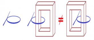
There is a primary, input winding made of usually copper conductors wound on a magnetic circuit, to which a certain voltage value is applied, and a secondary (output) winding, from the output terminals of which the voltage is removed, but already reduced to the required voltage value. Both windings are wound on the sides of the core and have no electrical connection with each other. The core, also known as the magnetic circuit, according to the law of electromagnetic induction, implements the entire process of voltage conversion in the device.
Figure 2. Transformer operating principle
Alternating current (varying over time with an operating frequency of 50 Hz) enters the input of the primary winding and flows through all the conductors of this coil, thereby inducing an EMF from its side of the core. According to the law of electromagnetic induction, a magnetic flux of a certain magnitude is induced in the magnetic circuit and begins to circulate. This magnetic field, in the course of a circular motion along the core, passes through the conductors of the secondary winding of the device, which is wound on the opposite side of the equipment and induces its own EMF of a smaller magnitude there (the example considers the step-down type of device). The magnitude of the EMF of the secondary winding by its action creates the rated current and voltage on the secondary winding, which are removed from its output terminals and are the result of the entire operation of the electric converter.
By changing the design of the core, the cross-section, the type of conductors and the number of turns in each of the windings, it is possible to vary the principle of operation of the equipment, using it as a step-down unit for transmitting electrical energy from the power source to the consumer, a step-up element as part of the “Generator-Transformer-Power Line” installation, or a transmission an element when it is necessary not to change the voltage value, but to use it in relay protection systems as a safe device that provides galvanic isolation for automation and protection.
Design features of dry cast resin transformers
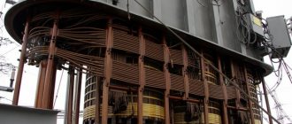
If we consider in detail the structure of a dry transformer with cast insulation, then paying attention to Fig. 3, one distinctive feature of the unit is highlighted, which is necessary for it to implement the process of natural air cooling of the entire electrical system - this is the almost complete absence of a solid equipment body, compared to other transformers that use oil or mixed cooling.
Figure 3. Dry-type cast resin transformer
The electrical, magnetic part of a dry-type transformer is not much different from other types of converters - its device has windings made of copper conductors of the primary and secondary types, one of which is connected to the energy source (primary), and the second is connected to the load - the voltage consumer. It contains a closed magnetic circuit and contact terminals necessary for normal conditions for the formation of electromagnetic induction and energy transformation.
The main differences between dry-type transformers begin in the insulation of the windings and the product housing.
Insulation performance is the main distinguishing feature of dry type equipment. For its production and creation they use:
- special insulating profiles with increased dielectric characteristics. Reinforced porcelain insulators are used to form the vertical and horizontal air cooling channels of the device;
- the material and the production of the insulation itself from it is carried out using a special technology and is in the form of a monolith (hence the name “cast”) by pouring epoxy dielectrics onto the copper conductors of the winding.
The second distinctive feature of dry type converters is its external design and dimensions. Compared to other types of similar electrical devices, dry-type transformers have large dimensions. In addition, they do not have a common one-piece cast body in their device, only individual elements of external protection (sheets for windings), strips for installing I/O contact parts, rigging during installation and a lower wheel structure for the ability to move at the time of primary installation and subsequent maintenance.
Such differences have a number of pros and cons in the main operation of the unit.
Advantages and disadvantages
Compared to oil-based ones, dry transformers have the following advantages:
- environmental safety - their operation does not involve the use of toxic substances with the subsequent need for their disposal. This significantly reduces the negative impact on the environment,
- ease of maintenance - no need to constantly replace and top up oil, control the tightness of components,
- safety in operation - such devices have a significantly lower fire hazard and risk of fire, the threat of thermal expansion of the oil with a possible explosion is eliminated,
- simplicity of design - this reduces the cost of production and ensures reliable operation,
- light weight - which is especially important for units of significant power due to the fact that no liquid dielectric is used.
Comparison of oil, dry and air transformers
Comparison of oil and dry transformers
Economic benefits of a dry-type transformer
Disadvantages are associated with relatively large dimensions. For powerful machines, it becomes necessary to significantly increase the volume of the case in order to increase the air gap for cooling.
The use of cast insulation poses a risk of mechanical failure when operating in conditions of low temperatures or sudden temperature fluctuations.
Application benefits
The design of dry-type transformers, due to their design features, the use of the latest, reinforced insulation materials, core, and housing elements, contains a set of advantages that can be divided into elements of interaction of converters with the environment and according to their technical characteristics and indicators.
Environmental friendliness
When interacting with the environment, during the full cycle of operation of such devices, after being written off for scrap, such equipment produces the least amount of pollution, both to the surrounding air and to the environment as a whole. This is due to the absence of a harmful, aggressive coolant environment, as in oil-type models, which, as a result of constant exhaust gases during operation, during accidents or repairs, cause significant harm to the environment with residual transformer oil, the breakdown of which or processing into an environmentally friendly product occurs or with difficulty or at high additional costs for such procedures.
Products that use natural air convection to cool their normal operation simply do not have such a volume of harmful substances, which means they are much cleaner according to environmental standards and regulations.
Fire safety
The reduction in the risk of fire in emergency operation, in the case of repair or adjustment work for dry-type transformers is also significantly lower compared to oil-type ones. The reason is also the lack of a fire-hazardous, flammable cooling liquid based on oil products. And the design of cast insulation, which is implemented on the basis of modern, high-strength, reinforced dielectric materials in the insulation of equipment windings, only increases their reliability and resistance to fires.
Based on the first two points of the advantages of dry-type devices, their use is recommended in areas where there is an increased risk of fire and better safety is required, like other electrical equipment, and working personnel.
Low noise pollution
The noise effect and its impact on both the environment and operating personnel occurs when the device is operating under load and depends on many factors, the main of which is the structure and shape of its magnetic part. Regardless of the type of converter, its ideal format, a silent type at the time of operation does not occur in nature.
Dry-type transformers have lower noise pollution during operation due to the manufacture of a laminated core and gluing, impregnation of its sheets with numerous layers of epoxy resins. The monolithic structure of the magnetic circuit thus formed produces significant noise attenuation when the transformer operates under load, in contrast to power units with an oil-fired or other type of structure.
High resistance to short circuit currents
Due to its design of the electrical part, insulation, and external casing, dry-type equipment is highly resistant to short circuit conditions and currents arising as a result of the formation of such a mode.
Power units with a rated power of more than 1000 kVA have a short-circuit voltage of 6-8% in normal operation, which increases the resistance limit of such products from the destructive effects of short-circuit currents.
Work in networks that are subject to lightning and switching overvoltages
The possibility of normal operation is due to the resistance of electrical equipment to short-circuit modes, the use in their design of a monolithic type of insulation of windings and contact parts based on modern epoxy materials with enhanced dielectric properties.
This priority of work expands their operating area not only in terms of the degree of danger of use, but in terms of the climatic conditions of zones with an increased threat of frequent thunderstorm fronts.
Easy installation
When installing it on site, there is no need to install a complex and sensitive fire extinguishing structure of the site with equipment, or adjust automation and alarm systems. This saves significant installation time. Dry converters do not have oil receivers, expansion tanks and other components necessary for commissioning oil-based energy conversion devices.
Taken together, the absence of all of the listed elements allows for easier installation of equipment on site and shorter diagnostic time during operation.
Economical
As for dry type converters in assessing their efficiency, this is their significant advantage. Due to the lack of fire extinguishing systems, the budget for the design of electrical installations, which include dry power modules for energy conversion, is significantly larger in volume.
The possibility of significantly close location of electrical equipment to consumers allows saving on less consumption of materials for the construction of transmission lines - their length is thereby significantly minimized, and power losses during the transfer of energy to end consumers are also reduced.
Automatic cooling control
The design of automation systems for cooling control in dry blocks is in most cases not required due to the basic principle of implementing cooling, built on the natural convection of air from the environment into the operating, transmitting transformer and back. The very operation of the dry-type installation, its design of the housing with special air channels allows semi-automatic control of heating of its entire electrical part.
Exceptions may be individual high-power products in a dry design, in which forced cooling installation projects are implemented through the additional installation of fans in individual parts of the transforming compartments.
Manufacturing technology of dry transformers
There are two main types of dry-type power transformers (besides the fact that the windings are made of either copper or aluminum): cast resin and air barrier insulation (open windings).
At the present stage of development of dry-type transformers, the manufactured windings are filled with epoxy compounds. Similar transformers are currently produced both abroad and in Russia and the CIS countries (METZ named after V.I. Kozlov RB, Transformer CJSC, Podolsk; SVEL Group of Companies, Yekaterinburg and others). There are two technologies for manufacturing dry power transformers with cast insulation: 1) vacuum technology; 2) roving technology.
When producing dry transformers using vacuum technology, the finished transformer windings are filled in a vacuum with an epoxy compound with a quartz filler (the so-called geafol), the preparation process of which also takes place in a vacuum. Until the end of the 50s of the last century, the technology of filling high-voltage windings of dry transformers with epoxy resin in air was widely used. In accordance with this technology, high voltage windings were impregnated with an insulating dielectric, and then they were dried. High-voltage transformer windings filled using this technology were of low quality, since the coils contained various impurities and micropores filled with air, which in many cases led to increased values of partial discharges, rapid aging of the insulation, reduced service life of the transformer, and in some cases could even cause an emergency insulation breakdown.
The simplicity of the technology for manufacturing windings impregnated in air also led to other, extremely undesirable, consequences: the windings were subjected to humidification and moisture absorption, which again caused surface discharges and accelerated aging of the insulation; transformers with such windings did not have the necessary mechanical strength, resistance to short circuit currents and were quite bulky.
The vacuum technology of filling transformer windings, which replaced the filling of windings in air, made it possible to completely eliminate various impurities and gas micropores from the insulation composition, and significantly improved the dielectric strength of the insulation with respect to partial discharges. The windings processed using this technology were closed on all sides with an epoxy shell with a thickness of 5 to 20 mm, which gave them the necessary rigidity and protected them from moisture and exposure to an aggressive environment.
The design and production technology of dry-type transformers at the highest technical level were developed by the famous company TRAFO-UNION, which sold its license to many companies. Thus, vacuum winding filling technology spread to many transformer plants and by the mid-1970s. became dominant in the production of epoxy transformers.
Transformers manufactured using the vacuum technology described above were considered trouble-free under any operating conditions, even the most extreme. But as the number of transformers in operation increased, the following shortcomings began to emerge:
- formation of cracks in the epoxy winding casing when overloaded at about 60...80% of the rated power of the transformer, which was initially in a cold state, or when the windings of a disconnected transformer are cooled to a temperature below -15...-20°C;
- The formation of cracks was caused by the fact that during sudden temperature changes, the rapidly heating winding material (copper) ruptured the epoxy-quartz winding body. insufficient resistance to dynamic short circuit forces;
- The high and low voltage windings constitute two independent winding cylinders, the mechanical strength of which in some cases is insufficient.
As a result of research, ABB developed a new technology for the production of cast resin transformers: by sealing layer windings using pure resin and glass filaments.
The idea of block winding is that the low and high voltage windings are connected to each other via fiberglass battens to form a single solid block.
By using approximately 80% glass fiber filling and optimally combining the transverse and cross directions of the glass fibers during the winding process, it is possible to obtain an extremely strong winding unit with high mechanical strength, which eliminates any movement of the windings under the influence of transverse or longitudinal forces.
This leads to high resistance to short circuits and stability of technical characteristics when exposed to low and high temperatures. Table 5. Dry transformers made in Russia and CIS countries
| Production capacities (Russia and CIS) of existing factories producing dry power transformers | Pieces/year (approximate data) | Type of dry-type transformers produced |
| OJSC Holding Company Elektrozavod, Moscow | 3000 | Cast insulation air barrier insulation |
| UE "METZ im. V. I. Kozlova", Republic of Belarus, Minsk | 4000 | Cast insulation air barrier insulation |
| LLC "Electrophysics", St. Petersburg | 1000 | Air barrier insulation |
| Group, Ekaterinburg | 1000 | Cast insulation |
| JSC "Kentau Transformer Plant", GC, Kentau | 1000 | Cast insulation air barrier insulation |
| OJSC "Ukrelectroapparat", Ukraine, Khmelnitsky | 500 | Cast insulation air barrier insulation |
| CJSC "Transformer", Podolsk | 1000 | Cast insulation |
| OJSC "NWTT", Yekaterinburg | 500 | Cast insulation |
| TOTAL: | 12 000 |
Features of various series
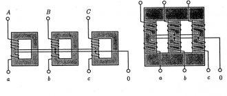
Based on Fig. 4 clearly shows that the second letter in the abbreviation of any transformer brand determines its type of cooling. For the dry look, the letter “C” will be used accordingly. Next comes the execution of the body.
Figure 4. Decoding the brand of power transformers
Even within dry cooling systems, there are several types of energy converters that have their own characteristics when releasing their series. It is worth considering the main ones, briefly describing the differences.
TSGL, TSDGL
According to the established decoding of the abbreviation of the product brand, we obtain:
- “T” – device – power converter.
- “C” – cooling type – dry type.
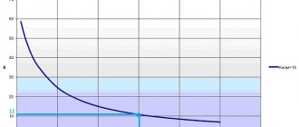
- “D” – the letter designation in the second mark of the chapter is the designation of the ambient temperature sensor included in the kit on a cable system with a length of at least 10 m, which allows you to control the heating modes of the room at various points. Its mobility ensures free movement of thermal protection and automatic fan control when used.
- “G” - type of insulation material - the use in the construction of a power unit of a special type of ultra-resistant insulation, which has a scientific name - geofolium. It has increased resistance and increased dielectric properties.
- “L” - the method of performing winding insulation - cast insulation indicates the production of a monolithic epoxy compound in the form of winding insulation, which allows it to have superior dielectric properties and strength.
A series of devices such as TSGL and TSDGL are usually made with a primary winding voltage in the range of 6-10 kV; the secondary winding of these devices reduces the voltage to 0.4 kV. Schemes and groups of connection of transformer windings are mainly:
- triangle - Star with grounded neutrals;
- star - A star with a neutral conductor.
The winding material is made from aluminum conductors in the original factory design. The insulation of the windings is additionally reinforced with a fiberglass mesh, which increases the resistance of the winding insulation in all respects and in emergency modes.
TSZGL, TSDZGL
The second series has a decoding of its abbreviations in almost the same version. The exception is the addition of the letter symbol “Z” - air cooling in a protected design. Here it is worth considering the details of the designed models depending on the busbar (bus or cable systems) of their primary and secondary outputs.
With LV and HV cable supply
In this design, the locations of the contact parts of the primary high-voltage and secondary low-voltage windings are reliably protected by the surface of the protective casing. The location for connecting the primary (HV) and secondary (LV) windings of cables on both sides of the device is located underneath it.
With LV bus terminals on the roof
If the connection of a dry voltage transformer is made by busbar in such a series and design, the HV contacts are located under the protective casing, and the LV part of the connection is brought to the roof of the casing and the busbar of the secondary winding is made there.
With LV and HV terminals on the roof
In this design, all contacts of the HV and LV parts of the dry-type transformer are brought out to the roof of the casing and can be connected to the electrical system both by bus and cable lines.
TSZGL11, TSDZGL11
The basic decoding of such series using alphabetic symbols is no different from the above equipment. The exception is the digital symbol in both brands of transformers - “11”; its presence indicates the displacement of the low-voltage terminals to the side of the protective casing of the dry-type mechanism. Moreover, both brands are designed for connecting both windings with cable lines.
TSZGLF11, TSDZGLF11
Another similar release of a series of blocks, differing in configuration, marked in the form of the letter symbol “F”, which indicates the flanged design of the main modules of the side part of the protective casing.
Distinctive class for heating resistance F type. The lateral arrangement of the HV contact parts is on the side flange, and the LV side is located on the roof of the protective casing. Possibility of inclusion in the power supply system using buses or cables for the secondary winding and only busbars for connecting high-voltage transformer inputs.
- Dry power transformers type TS, TSZ
- Dry power transformers type TSGL, TSZGL
- Dry power transformers type TSN, TSZN
Dry power transformers type TSN and TSZN with windings made of wires with Nomex insulation of heat resistance class N (180°C).
Used in many sectors of the national economy; designed for converting electrical energy in three-phase alternating current power networks with a frequency of 50 Hz; are installed in industrial premises and public buildings, which have increased requirements in terms of fire safety, explosion protection, and environmental cleanliness.
Technical data
Power transformers of the TSN and TSZN types are manufactured with a power from 25 to 2500 kVA with a rated voltage of the primary winding (high voltage) up to 10 kV inclusive and a secondary winding (low voltage) - 0.4 kV.
terms of Use
— ambient temperature: from -5°С to +40°С; — relative air humidity — no more than 98% at a temperature of +25°C; — installation height above sea level — no more than 1000m; — the environment is non-explosive and does not contain conductive dust.
Transformer design
Transformers consist of the following main assembly units: - magnetic circuit; — windings placed on the magnetic core (active part); — taps (inputs, HV and LV busbars); - protective casing.
The magnetic core is made of high-quality electrical steel. Special cutting on the Georg line and assembly methods using bands, tie rods and special adhesives ensure low no-load losses and low noise levels. Organosilicon paints are used to protect against corrosion.
LV windings are made of copper or aluminum wires with Nomex insulation or copper or aluminum foil. Nomex paper is used as interlayer insulation.
Dry power transformers type TS, TSZ
TS, TSZ
Brief characteristics: Type - TS, TSZ Power 10 - 100 kVA Voltage class 6-10 kV
Three-phase dry transformers without casing (TC) and with casing (TSZ) of voltage class 0.66 kV with power from 0.1 to 100 kVA with any combination and voltage of windings.
Three-phase dry transformers of the TS and TSZ series are designed for converting electricity from consumers. Transformers are highly reliable, require minimal maintenance costs, are economical, and easy to operate.
TS transformers are of unprotected design (protection level IP 00).
TSZ transformers are of protected design (protection degree IP 21).
The corrected sound power level is no more than 60 dBA.
Type of climatic modification UHL, placement category 4.
Technical characteristics of transformers type TS, TSZ
Rated
power, kVA
| Losses, VT | Short voltage short circuits, % | ||
| idle move | short circuit | ||
| 10 | 80 | 300 | 3,8 |
| 16 | 120 | 400 | |
| 25 | 155 | 600 | |
| 40 | 220 | 880 | |
| 63 | 290 | 1280 | |
| 100 | 390 | 1450 | |
Dimensional and weight characteristics of TS type transformers
| Rated power, kVA | Weight, kg | Length, mm | Width, mm | Height, mm |
| 10 | 120 | 630 | 440 | 720 |
| 16 | 132 | |||
| 25 | 177 | 680 | 780 | |
| 40 | 220 | 720 | 810 | |
| 63 | 287 | 760 | 900 | |
| 100 | 445 | 870 | 550 | 950 |
Dimensional and weight characteristics of transformers type TSZ
| Rated power, kVA | Weight, kg | Length, mm | Width, mm | Height, mm |
| 10 | 138 | 780 | 440 | 880 |
| 16 | 150 | |||
| 25 | 195 | 810 | 940 | |
| 40 | 240 | 880 | 980 | |
| 63 | 310 | 920 | 1110 | |
| 100 | 480 | 980 | 550 | 1120 |
Dry power transformers type TSGL, TSZGL
TSGL, TSZGL
Brief characteristics: Type - TSGL, TSZGL Power 160 - 2500 kVA Voltage class 6-10 kV
Power transformers of the TSZGL type with a power from 100 to 2500 kVA with a rated voltage of the primary winding (high voltage) up to 20 kV inclusive and secondary winding (low voltage) - 0.4 kV.
Voltage regulation - non-excited jumper switching to ±5% or ±2.5% UH.
Technical characteristics of dry transformers of the TSZGL series
| Rated power, kVA | Losses, VT | Short circuit voltage, % | |
| idle move | short circuit | ||
| 160 | 850 | 2300 | 4 |
| 250 | 1000 | 2890 | |
| 400 | 1150 | 3790 | 6 |
| 630 | 1600 | 5800 | |
| 1000 | 2100 | 7900 | |
| 1600 | 3100 | 11500 | |
| 2500 | 4800 | 17000 | |
Dimensional and weight characteristics
| Rated power, kVA | Weight, kg | Length, mm | Width, mm | Height, mm |
| 160 | 1310 | 1380 | 925 | 1380 |
| 250 | 1670 | 1700 | 1050 | 1580 |
| 400 | 1700 | 1760 | 1640 | |
| 630 | 2500 | 1820 | 1188 | 1850 |
| 1000 | 3050 | 1980 | 1224 | 1950 |
| 1600 | 4100 | 1298 | 2320 | |
| 2500 | 6900 | 2850 | 1455 | 2735 |
Dry power transformers type TSN, TSZN
TSN, TSZN
Brief characteristics: Type - TSN, TSZN Power 25 - 2500 kVA Voltage class 6-10 kV
Technical characteristics of dry transformers of the TSN series
| Rated power, kVA | Losses, VT | Short voltage short circuits, % | |
| single progress | short closures | ||
| 25 | 150 | 600 | 4,0 |
| 40 | 220 | 880 | |
| 63 | 300 | 1280 | |
| 100 | 400 | 1720 | |
| 160 | 570 | 2300 | |
| 250 | 750 | 2900 | 4,5 |
| 400 | 820 | 4300 | 6,0 |
| 630 | 1300 | 5500 | |
| 1000 | 1900 | 8250 | |
| 1600 | 2500 | 12350 | |
| 2500 | 3500 | 15300 | |
Dimensional and weight characteristics
| Rated power, kVA | Weight, kg | Length, mm | Width, mm | Height, mm |
| 5 | 680 | 1000 | 680 | 900 |
| 40 | 740 | |||
| 63 | 900 | 1100 | 735 | 950 |
| 100 | 930 | 1000 | ||
| 160 | 990 | 1510 | 1135 | 1530 |
| 250 | 1310 | |||
| 400 | 1600 | 1710 | 1640 | |
| 630 | 2300 | 1850 | ||
| 1000 | 3200 | 1920 | I960 | |
| 1600 | 4400 | 2220 | 1310 | |
| 2500 | — | — | — | — |
Electrical and noise characteristics depending on power
The parameters of the electrical part of energy converters from one voltage class to another are directly proportional to the rated power of the device. It is a known fact that the more energy consumers and receivers of electrical energy need to be powered, the more power the power transformer needs, regardless of the type of cooling.
And therefore, even in dry conversion units, with an increase in the required power, it is necessary to expand, increase the cross-section of the conductors of the windings of both sides of the device, and increase their size, which in turn provokes a further increase in the remaining geometric parameters of the equipment.
At present, an ideal device of enormous power, but with minimal dimensions, has not yet been invented, just like normally constantly working superconducting materials. However, in dry types, due to the lack of oil cooling systems and components, the entire electrical part is located in the most compact design, depending on the series of devices.
The noise power characteristics of dry-type voltage transformers have the same direct relationship, proportional to the power of the power unit and in basic nominal values varies in values and tolerances equal to 50 -70 dB, but no more.
What is it used for and where can it be used?
A dry transformer produced in Russia provides a decrease or increase in the voltage value, which is determined by the needs of the consumer. Converting electrical parameters is an important step, without which it would be difficult to provide facilities with electricity, since this requires changing the high-voltage voltage of power lines to a lower one. Due to the absence of an oil dielectric, such devices are called dry. This means that the design includes an air cooling system.
The dry step-up power transformer is designed to implement the function of converting electricity with its further distribution and transmission. The electricity generated by the generator occurs at low voltages (no more than 24 V), and in order to transmit it through high-voltage lines without significant losses, it is desirable to increase the voltage value to a higher level (from 110 to 750 kW, depending on needs). At the same time, such devices also perform a reduction function.
Additionally, a dry-type transformer with a capacity of 400 kVA (above or below) can power electrical installations, equipment and electrical appliances. This means that this type of equipment is widely used in power supply networks, in production, and to provide electricity to facilities for various purposes.
Dimensions and weight
The presence of additional elements in dry energy converters determines its design dimensions and weight. They differ and are divided into production series. This is the easiest way to highlight them here
TSGL, TSDGL
Devices with geofoil insulation reinforced with fiberglass, but without protective casings, have the following geometric parameters of their “body” in the power range of 100-2500 kVA:
Table 1. Overall dimensions and weight of TSGL, TSDGL in the main limits of size and power
| Brand Transformer TSGL/TSDGL | Overall dimensions Length x Width x Height, mm | Wheel track, axle size, mm | Net weight of dry products, kg | |
| Protection degree IP00 | Protection degree IP21 | Protection degree IP00/IP21 | ||
| from 100 before 2500 kVA | 1250x800x1000 to 1720x1430x2100 | 1250x1000x1000 Before 1720x1530x2100 | 660 Before 1070 | 750 Before 4450 |
A more detailed storyboard of the overall dimensions and weight of devices for a specific power can be obtained on the websites of manufacturers, or in reference technical literature. In Table. 1 shows the minimum and maximum parameters of devices for general illumination of their minimum and maximum dimensions and weight.
TSZGL, TSDZGL
Here it is worth describing the parameters again based on the type of arrangement of the inputs on the protective casing on each side of the windings and the type of their busbar.
With LV and HV cable supply
The publication again outlines their minimum and maximum parameters in terms of size and tonnage depending on the power range
Table 2. TSZGL/TSDZGL with cable supply to LV and HV
| Brand Transformer TSZGL/TSDZGL | Overall dimensions Length x Width x Height, mm | Wheel track, axle size, mm | Net weight of dry products, kg | |
| Protection degree IP00 | Protection degree IP21 | Protection degree IP00/IP21 | ||
| from 100 before 2500 kVA | 1340x810x1540 to 2250x1500x2370 | 1340x1110x1540 Before 2250x1520x2370 | 660 Before 1070 | 850 Before 5380 |
Analyzing the second parametric table and comparing it with the first, it becomes clear that the additional structure in the form of a protective casing makes adjustments to the dimensions of the conversion equipment in the direction of increasing both its operating weight and overall dimensions.
With LV bus terminals on the roof
Another option is worth considering due to technical parameters, when the connection to the contact parts is made mainly by the bus and only on the LV side of the device
Table 3. TSZGL/TSDZGL with LV busbar supply on the roof
| Brand Transformer TSZGL/TSDZGL | Overall dimensions Length x Width x Height, mm | Wheel track, axle size, mm | Net weight of dry products, kg | |
| Protection degree IP00 | Protection degree IP21 | Protection degree IP00/IP21 | ||
| from 100 before 2500 kVA | 1650x910x2260 to 2250x1500x2470 | 1650x1110x2260 Before 2250x1520x2470 | 660 Before 1070 | 1350 Before 5380 |
Within product series, changes in the type of busbar and the location of inputs have a rather critical effect on the size and weight of the equipment.
With LV and HV terminals on the roof
The latest publication of technical parameters for dry-type transformers with a protective casing, where the contact parts are located on the roof of the casing of both windings and it is possible to connect both a cable and a bus to them in Table. 4.
Table 4 TSZGL/TSDZGL With LV and HV terminals on the roof
| Brand Transformer TSZGL/TSDZGL | Overall dimensions Length x Width x Height, mm | Wheel track, axle size, mm | Net weight of dry products, kg | |
| Protection degree IP00 | Protection degree IP21 | Protection degree IP00/IP21 | ||
| from 100 before 2500 kVA | 1470x910x1540 before 2445x1500x2370 | 1470x1110x1540 Before 2445x1520x2370 | 660 Before 1070 | 850 Before 5380 |
There is some similarity with previously published types of devices without protective casings, but there are strong discrepancies in power gradation by size, hence the size and weight table for them has been published additionally.
TSZGL11, TSDZGL11
Devices with a parameter for lateral displacement of the terminals on the casing have separate geometric criteria and mass parameters.
Table 5. TSZGL11/TSDZGL11 Data on the dimensions of equipment with lateral displacement of inputs
| Brand Transformer TSZGL11/TSDZGL11 | Overall dimensions Length x Width x Height, mm | Wheel track, axle size, mm | Net weight of dry products, kg | |
| Protection degree IP00 | Protection degree IP21 | Protection degree IP00/IP21 | ||
| from 100 before 2500 kVA | 1470x910x1540 before 2445x1500x2370 | 1470x1110x1540 Before 2445x1520x2370 | 660 Before 1070 | 850 Before 5380 |
Despite the lateral arrangement of the contacts, their design is similar to the previous series of transformers.
TSZGLF11, TSDZGLF11
The presence of a flange at the location of the side winding contacts on the protective casing did not make any difference in either the weight or dimensions of the voltage transformers. Flange devices have the same meanings as in Table. 5. Repeated publication of the same size and weight table for them in this article would be redundant.
Specifications
- Rated power - determines the volume of processed electricity for a dry transformer.
- Rated voltage - shows the value of the voltage level that can be supplied to each of the high, medium and low potential windings.
- Overload factor – shows by what amount the workload can exceed the rated current value.
- No-load and short-circuit loss coefficients
- The degree of dust-moisture resistance and climatic performance determines the external conditions under which the unit can be operated and the insulation strength is maintained.
- Overall dimensions and weight of a dry-type transformer.
- Noise level.
To enlarge the table with characteristics, click on it:
Temperature relay connection diagrams
The temperature control system for dry voltage converters on all three phases and at several points of the core is implemented automatically based on the connection of a thermal relay of the RT 100 type, connected via temperature sensors to the temperature measurement points of the operating equipment.
The thermal relay is located on the housing of the power plant in a place on the housing convenient for maintenance and reading indicators on a universal DIN rail.
The connection diagram for the contact parts of the thermal relay control to the transformer is given below.
Figure 5. Thermal relay RT 100
The limit of maximum and minimum response thresholds for signaling an emergency or shutdown mode of a power device can be set by maintenance personnel, but it should not exceed the permissible values of 140-1500 C for the standard insulation resistance class and higher for more reinforced ones. In Table. 6 these characteristics are described in detail for each class.
The relay is connected to the power supply through modular differential protection, and is also connected by its contacts to the power coils of cooling fans of certain areas of dry-type equipment, when the PT 100 is triggered, which begin forced airflow into these areas of the device.
Permissible overloads
Dry-type power transformers are divided depending on the heating class of insulation resistance according to established standards. Based on them, there is a parametric table of tolerances for temperature overloads of power devices.
Table 6. Permissible overloads of dry type transformers
| Device insulation type according to heating resistance class with temperature range | Triggering of thermal probes installed on the transformer upon an “ALARM” | Triggering of thermal probes installed on the transformer upon the “SHUTDOWN” signal |
| Class "B" = -50 to 1200 C | 1200 C | 1300 C |
| Class "F" = -50 to 1550 C | 1400 C | 1500 C |
| Class "H" = -50 to 1800 C | 1600 C | 1700 C |
Thus, if dry transformers are selected in a climatic zone with an increased temperature balance for long-term operation, it is imperative to select them with an insulation resistance heating class of at least “H”, based on the values given above.
How to arrange ventilation in compartments
For optimal creation and implementation of natural air cooling of a power transforming unit, electricity is necessary in the compartments where its permanent installation and connection is planned, the creation of a correct supply and exhaust ventilation scheme.
Some recommendations for creating them in a short diagram and with a short description are given below.
Figure 6. Creation of ventilation for dry transformers in their operating area
Calculation of the selection of the supply and exhaust openings indicated in Fig. 6 S1/S2 is produced using special calculation formulas and depends on several parameters of the power converter, as well as on the dimensions of the compartment itself in which the installation takes place. It is better to entrust these calculations either to computerized services for calculating technical parameters for optimal operation of transformers or to attribute them to the design bureaus that design the future electrical installation or part of it.
Application area
Rice.
7. Practical application of dry transformers In view of the widespread use of electrical energy for all production and technological processes, dry transformers, as high-voltage converters, have a fairly wide application. They are used to supply power to ground electrified transport systems, traction and transformer substations, and power production workshops. In addition to the industrial sector, dry aggregates are used in the agricultural industry, for shopping complexes, resort centers and villages. In everyday life, they are used to supply power to apartment buildings, schools and preschool institutions.
The scope of application of low-current low-power dry transformers is practically unlimited. These are all kinds of household appliances, devices and devices for small-scale mechanization, converters and welding equipment.