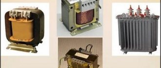
Any transformer, with the exception of an autotransformer, has at least two windings: high and low voltage. Also, for three-phase devices, each of the windings consists of three parts (according to the number of phases). The large number of parts allows for multiple inclusion options. To avoid confusion, all transformer winding connection groups for three-phase devices are standardized and brought into a single system for error-free connection of devices and the possibility of parallel operation.
The concept of a group connecting the windings of a three-phase transformer
Three-phase networks use two types of connections: star and delta. When making structures, it may seem that there are only four types of winding arrangements:
- Star-star.
- Star-triangle.
- Triangle-star.
- Triangle-triangle.
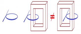
In reality, everything is more complicated, since in each type of connection (star or triangle) the parts of the windings can be connected differently. An example is a conventional two-winding transformer. If such a device has the same beginnings and ends of the windings, then the phase shift will be equal to 0. Turning one of the windings will give a phase shift of 1800.
There are also z-shaped winding connections (zigzag). In such designs, each of the windings consists of two parts located on different cores of the transformer magnetic circuit.
A three-phase network is characterized by a phase shift relative to one another by 1200. Therefore, there are a total of 12 connection groups. Each group is characterized by a certain shift of the same phases at the input and output of the transformer.
How to connect two primary and two secondary windings of a transformer
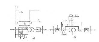
A typical transformer primary connection is shown in the image on the left.
With a parallel connection, the supply voltage of the parallel-connected primary windings of the transformer will remain unchanged in our example 120 v.
In the case of a serial (Series) connection, the supply voltage will double. With this connection, we can now supply a total of 240v voltage to one winding.
Typical connection of the secondary windings of a transformer.
1. The first option is when we use it as is. Each secondary winding of the transformer powers its own load.
2. The second option is a series connection of the secondary windings of the transformer.
As a result, we will get double the voltage at the 2*12 output.
We will get an output voltage of 24v at the same currents as in the circuit of independent operation of the secondary windings.
3. The third option is a scheme with a midpoint. This option is applicable in circuits with bipolar power supply.
4. The fourth option is a parallel connection of the secondary windings of the transformer. This circuit doubles the output current. Increases output power, voltage remains the same.
Symbols and explanation
Groups are marked with numbers from 0 to 11. For convenience and standardization, the following is accepted:
- connections of the same type (∆/∆, Y/Y) have even numbers;
- heterogeneous connections (∆/Y, Y/∆) – odd.
Three-phase transformers are made on core magnetic cores. Each phase is located on a separate rod. This greatly simplifies further work and coordination of devices with each other.
If a transformer has identical phases wound on the same rods, then the groups of connections are called main (0, 6, 11, 5). The remaining groups are derivatives.
Since the minimum phase shift can be 300, the number of options is 12, which corresponds to the positions of the clock hands. The 0th and 12th positions are the same. Based on this, they say that the group number coincides with the position of the hour and minute hands. The phase shift is calculated simply:
Group number*300.
The following designations are accepted on electrical circuits and devices:
- Y, U – star;
- Yn, Un – star on the low voltage side;
- Yo, Uo – star with zero point;
- ∆, D, D – triangle;
- ∆н, Дн, Dн – triangle on the low voltage side.
An example of marking a two-winding transformer:
- ∆/Yн – 11. Primary winding triangle, secondary (step-down) star. Phase shift 3300;
- Y/Yо -0. Both windings are connected in a star, the secondary with the zero point removed. There is no phase shift.
Also on electrical diagrams, high voltage (HV) windings are designated by the following symbols:
- A, B, C – beginning of the winding;
- X, Y, Z – end of the winding.
Likewise for the low voltage side:
- a, b, c;
- x, y, z.
Multi-winding devices are marked in a similar way, for example:
Yo/Y/∆ – 0 – 11.
Instead of the zero group, the twelfth group can be indicated, which is completely equivalent.
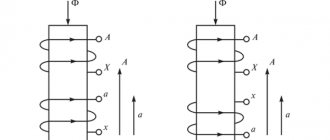
Star connection of transformer windings
When connected into a star, the following relations apply:
- line currents are equal to phase currents,
- linear voltages are √3 times greater than phase voltages
There are many options for connecting the transformer windings in a star, some of them are shown in the figure below. And, as they say, not all of them are equally useful, or rather, different connection diagrams are needed for different cases.
It should be noted that either one three-phase transformer or three single-phase ones can be connected into a star. The figure indicates:
- A, B, C – the beginning of the high voltage windings
- X, Y, Z – ends of high voltage windings
- a, b, c – the beginning of the low voltage windings
- x, y, z – ends of low voltage windings
How vector diagrams are constructed
When constructing vector diagrams, you need to remember the rule that the phase shift between the phases is 1200, that is, if the voltages are equal, the ends of the vectors will always form an equilateral triangle.
The simplest diagram to draw is for a star connection. A point is placed in the center of the diagram, which corresponds to the combined ends of the windings. Phase vectors are drawn from the center at angles of 1200. The vector of the middle phase is drawn vertically.
For a triangle, draw a line parallel to the corresponding phase of the star, and from its ends, respectively, the remaining two phases are connected to it. The condition must be met - all sides of the triangle must be parallel to the corresponding phases of the star. The required vectors will be lines drawn from the center of the triangle to its vertices.
Vector diagrams are drawn for the high and low sides and then aligned with a single center. The angle between like phases will indicate the connection group number expressed in hours.
The count must be taken from the high voltage vector to the low one.
Connection group table
The table below shows the designations of the connection groups and the phase rotation of the low and high sides.
| Connection group | Designation | Phase rotation |
| 0 | Y/Y-0 | C, B, A |
| c, b, a | ||
| ∆/∆-0 | C, B, A | |
| c, b, a | ||
| 1 | Y/∆-1 | C, B, A |
| c, b, a | ||
| ∆/Y-1 | C, B, A | |
| c, b, a | ||
| 2 | Y/Y-2 | C, B, A |
| c, b, a | ||
| ∆/∆-2 | C, B, A | |
| a, c, b | ||
| 3 | Y/∆-3 | C, B, A |
| b, a, c | ||
| ∆/Y-3 | C, B, A | |
| b, a, c | ||
| 4 | Y/Y-4 | C, B, A |
| b, a, c | ||
| ∆/∆-4 | C, B, A | |
| b, a, c | ||
| 5 | Y/∆-5 | C, B, A |
| c, b, a | ||
| ∆/Y-5 | C, B, A | |
| c, b, a | ||
| 6 | Y/Y-6 | C, B, A |
| c, b, a | ||
| ∆/∆-6 | C, B, A | |
| c, b, a | ||
| 7 | Y/∆-7 | C, B, A |
| c, b, a | ||
| ∆/Y-7 | C, B, A | |
| c, b, a | ||
| 8 | Y/Y-8 | C, B, A |
| a, c, b | ||
| ∆/∆-8 | C, B, A | |
| c, b, a | ||
| 9 | Y/∆-9 | C, B, A |
| b, a, c | ||
| ∆/Y-9 | C, B, A | |
| b, a, c | ||
| 10 | Y/Y-10 | C, B, A |
| c, b, a | ||
| ∆/∆-10 | C, B, A | |
| b, a, c | ||
| 11 | Y/∆-11 | C, B, A |
| c, b, a | ||
| ∆/Y-11 | C, B, A | |
| c, b, a |
Determination by galvanometer method
There are several ways to determine whether the windings are connected correctly. The easiest way is to use a magnetoelectric system voltmeter. It is also called the direct current method.
To do this, a measuring device is connected to the ends of the winding being tested, and a constant voltage is applied to the other winding. The deflection of the arrow at the moment the key is closed will indicate the polarity of the winding connection. Such actions are performed for each winding.
You can also use a simple voltmeter when connecting AC voltage. To do this, a reduced alternating voltage is supplied to one of the windings, and the remaining two windings are connected in series and connected to a voltmeter. Absence or too small readings indicate that the windings are connected in opposite directions.
How to connect two primary and two secondary windings of a transformer
How to connect two primary and two secondary windings of a transformer
A typical step-down transformer with two Primary and two Secondary windings is shown in the image.
The dark dot indicates the beginning of the winding (identical polarity of the windings at a given point)
By combining the primary windings with each other, we thereby assign the transformer to be used either in a network with an alternating current voltage of 110 -120 vv, or in an alternating current network of 220 - 240 vv.
By combining the secondary windings of the transformer and depending on the combination circuit, we thereby determine which circuit solution will use one or another circuit for combining the secondary windings of the transformer.
By manipulating the way the primary and secondary windings of the transformer are connected together, we can increase or decrease the output voltage or power. As well as input voltage limits.
Examination
If the transformation ratio is known, then using a voltmeter you can determine the number of the main connection group. For this purpose, voltage is applied to ends A and a or x and y and the voltages are measured at terminals B-c and C-c when connected in a star, or By and Cz when connected in a triangle. The following ratios are used for verification:
UBb = UCc = UAa(k-1) Group Y/Y-0
UBy = UCz = Uxy(k+1) Y/Y-6
UBb = UCc = UAa(√(1-√3k+k2)) Y/∆-11
UBy = UCz = Uxy(√(1+√3k+k2)) Y/∆-5
To avoid equipment damage, emergency situations and injury, all measurements should be made at low voltage, without connecting the equipment to the main network of the enterprise.
Voltage transformer connection diagrams
Single-phase voltage transformers, depending on their purpose, are interconnected in various circuits.
In Fig. Figure 2-3 shows the basic connection diagrams for single-phase voltage transformers .
Figure (a) shows a diagram for connecting one VT AC voltage .
This circuit is used when only one phase-to-phase voltage is needed for protection or measurement.
In Fig. (b) shows a diagram of connecting 2 VTs into an open triangle (or partial star ). This circuit is used when two or three phase-to-phase voltages are required for protection or measurement.
In Fig. (c) shows a diagram of connecting 3 single-phase VTs into a star . This scheme has become widespread and is used when phase voltages or simultaneously phase and phase-to-phase voltages are needed for protection and measurements.
The connection of 3 single-phase VTs triangle-star circuit is shown in Fig. (G). This circuit provides a voltage on the secondary side equal to
In Fig. (e) shows a diagram of connecting the windings of 3 single-phase voltage into a zero-sequence voltage filter . In this circuit, the primary windings of the VT are connected in a star with a grounded neutral, and the secondary windings are connected in series, forming an open (not closed) triangle . The voltage at the terminals of the open triangle is equal to the geometric sum of the zero-sequence voltages of the secondary windings:
Since the sum of the 3-phase voltages is equal to triple the zero-sequence voltage, then
Consequently, a voltage proportional to the zero sequence voltage is obtained at the terminals of the open delta circuit .
In normal modes and during short circuit. without ground Up=0 , because the voltage vectors do not contain a zero sequence.
With short circuit to ground in networks with a grounded neutral and in case of ground faults in networks with an isolated neutral, the geometric sum of phase voltages is not equal to zero due to the appearance of a zero-sequence voltage and a zero-sequence voltage of 3U0 .
Thus, the considered circuit is a zero-sequence voltage filter.
It should be noted that a prerequisite for the operation of the considered circuit (e) as a filter U0 is the grounding of the neutral of the primary windings of the VT , since in the absence of grounding, the primary windings of the VT will be supplied not with phase voltages relative to the ground, but with phase voltages relative to the isolated neutral, the sum of the voltages of which is not contains U0 and their sum is always zero and during a ground fault there will be no voltage at the output of the circuit.
In Fig. 2-4 shows a connection diagram for a voltage transformer with two secondary windings. Here, the primary and main secondary windings are connected in a star, and the additional secondary winding is connected in an open delta (to the sum of the phase voltages - to obtain the zero-sequence voltage necessary to turn on the voltage relay and the power direction relay for protection against single-phase short circuits in networks with grounded neutral, as well as for insulation monitoring devices acting on the signal in networks with an isolated neutral).
As is known, the sum of 3-phase voltages in normal mode, as well as with 2 and 3-phase short circuits. equal to zero. Therefore, under these conditions, the voltage at the terminals of the open delta will be zero.
Typically, at the terminals of an open delta in normal mode (in the absence of a ground fault) there is a small voltage of 0.5-2 V , which is called unbalance voltage .
At 1f. short circuit in a network with a grounded neutral, the phase voltage of the damaged phase becomes equal to zero, and the geometric sum of the phase voltages of 2 undamaged phases turns out to be equal to the phase voltage.
In case of single-phase ground faults in a network with an isolated neutral, the voltages of the undamaged phases become equal to the phase-to-phase voltage, and their geometric sum turns out to be equal to triple the phase voltage. In this case, so that the voltage on the relay does not exceed the nominal value of 100 V , for transformers intended for operation in networks with isolated neutrals, the secondary additional windings connected in an open delta circuit have a transformation ratio increased by 3 times (for example,).
It should be borne in mind that when the primary windings of the voltage transformer are connected to phase voltages, they must be connected into a star, the zero point of which must be connected to ground . Grounding of the primary windings is necessary so that at 1ph. short circuit or ground faults in the network where the VT , instruments and relays connected to its secondary winding correctly measured the phase voltages relative to the ground.
Grounding of the secondary windings is also mandatory regardless of their connection diagram because This grounding is protective - it ensures the safety of personnel when high voltage enters the secondary circuits. Usually one of the phase wires (usually phase B ) or the star zero point is grounded.
The primary windings of voltage up to 35 kV are connected to the network through high-voltage fuses to quickly disconnect a damaged transformer .
To protect the voltage in case of damage, low voltage circuit breakers (or fuses) are installed in the secondary circuits.
Secondary VT must be constructed with a high degree of reliability, excluding breaks and loss of contacts to prevent the disappearance of voltage at the protections, since the disappearance of voltage will be perceived by the protections as a decrease in voltage during a short circuit. in a protected network and can lead to their incorrect operation. The loss of voltage from the transformer voltage due to malfunctions or blown fuses will also be perceived by the protections as a loss of voltage and can also lead to their incorrect operation. Therefore, protections that respond to a decrease in voltage are designed in such a way that they distinguish short circuits. from malfunctions in secondary circuits, or are equipped with special devices - interlocks in case of malfunctions in voltage circuits.
Examples of group winding connections
The state standard provides only two groups of winding connections:
- Y/Y-0 or ∆/∆-0
- Y/∆-11 and ∆/Y-11
Strict standardization eliminates accidents and damage resulting from incorrect connections. In addition, for transformers of the same power and transformation ratio, parallel connection of devices becomes possible.
The remaining number of connections is used extremely rarely in some cases when it is impossible to use the standard option.
The type of connection must be specified in the accompanying documentation and duplicated on the device nameplate.
Erroneous designations
Erroneous connections occur when the rules for connecting the ends are not followed. This occurs as a result of incorrect winding or incorrect designation. As a result, when the device is connected to a three-phase network, the windings connected in opposite directions compensate each other’s magnetic fluxes, so a current begins to flow through them, limited only by the active resistance of the winding wire, which is equivalent to a short circuit.
To eliminate cases of incorrect switching, it is recommended that after repairing equipment or before switching on unknown devices, carefully check the phasing of each winding using several methods to eliminate possible errors.
A preliminary calculation of voltages for measurements using the voltmeter method will help reduce the likelihood of error. The data obtained serve as guide values that need to be taken into account when making subsequent measurements.