Transformers. Typical faults of transformers and ways to eliminate them.
1. “Aging” of the intersheet insulation of the magnetic circuit
, some local damage to it, short-circuiting of individual sheets. Signs of damage are an increase in current and no-load losses, rapid deterioration of the oil, a decrease in its flash point, an increase in oil acidity and a decrease in breakdown voltage.
2. "Fire" of steel
,
damage to the insulation of the coupling bolts
,
shorting of the sheets of the magnetic circuit
, contact of some metal parts in two places of the magnetic circuit, as a result of which closed circuits for vortex flows are formed. Signs of damage are an increase in the temperature of the transformer, the appearance of black or brown gas in the gas relay, which ignites when ignited. The oil changes color, becomes dark and has a sharp specific odor due to decomposition (cracking process).
3. Loosening the compression of the magnetic circuit
, free vibration of fastening parts, vibration of the outer sheets of the magnetic circuit. Signs of damage include abnormal buzzing, rattling, or buzzing sounds. These same signs may also be a consequence of an increase in primary stress compared to normal.
4. "Aging" and wear of insulation
. Insulation wear can occur due to long-term use of the transformer, but premature wear can also occur as a result of frequent overloads or insufficient cooling at rated load. Deterioration of cooling conditions can occur due to sludge deposits on the windings, contamination of the spaces between windings, and “aging” of the oil.
In practice, the following division of insulation into suitability classes is accepted:
1st class - the insulation is elastic, soft, does not crack or deform; such insulation is considered good; 2nd class - the insulation is hard, durable, without cracks, does not crack or deform when pressed by hand and is difficult to separate with a knife; this state of insulation is considered satisfactory; 3rd class - the insulation is fragile, when pressed or tapped, it delaminates or small cracks and deformations appear; 4th class - the insulation has cracks, crumbles when pressed by hand, bare areas are noticeable; the insulation is considered poor and windings need to be replaced.
To determine the strength of insulating gaskets in repair practice, the condition of electrical cardboard is checked using samples cut from the insulation of various parts of transformers. The cut strip of electrical cardboard is bent with your fingers at a right angle or folded in half without squeezing the folded sheet. If the electrical cardboard does not break when fully bent in half, the insulation is considered good; if it breaks when fully bent, then it is satisfactory, i.e., of limited use, and if the cardboard breaks even when bent to a right angle, then it is unusable.
5. Turn short circuit in windings
. Such a short circuit occurs when the winding insulation is destroyed due to wear, deformation of the windings during a short circuit, load shock, various kinds of overvoltages in emergency modes, a decrease in the oil level until the windings are exposed, and in other cases. Signs of damage - operation of the gas protection to turn off the transformer with the release of flammable gas of a white-gray or bluish color; abnormal heating of the transformer with characteristic gurgling, unequal resistance of the phase windings when measured with direct current. In case of significant turn faults, maximum protection is activated.
b. Winding break
, which occurs when the output ends burn out due to the thermal action and electromechanical forces of short circuit currents, poor soldering of conductors, and burnout of part of the turns during turn faults. Signs of damage are the operation of the gas protection due to the formation of an arc at the break point.
7. Breakdown and overlapping of the internal and external insulation of the transformer
. The reasons for the overlap may be significant wear of the insulation, the appearance of cracks in it, into which dirt and dampness enter, as well as atmospheric and switching overvoltages. Let's take a closer look at possible malfunctions of power transformers.
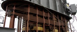
Transformers
domestically produced, simple in design, reliable and easy to use. Cases of damage to transformers are caused by: violation of current operating rules, emergency and abnormal operating modes, aging of winding insulation, poor quality assembly at the factory or during installation and repair. Experience in the installation and repair of transformers shows that two thirds of damage occurs as a result of unsatisfactory repair, installation and operation and one third is due to manufacturing defects. The main damage occurs to windings, taps, terminals and switches (about 84%).
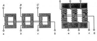
The most serious malfunction of transformers occurs when magnetic circuits are damaged (“steel fire”)
, due to a violation of the insulation between the individual sheets of steel and the bolts holding them together. In butt magnetic circuits, the cause of accidents is a violation of the insulation at the joints between the yoke and the rods. Local heating of the magnetic core steel occurs as a result of destruction or wear of the insulation of the coupling bolts, damage to the intersheet insulation and poor contact of electrical connections. Interturn short circuits in windings and sectional breakdowns and short circuits occur under shock loads or short circuits and as a result of deformation of sections from mechanical forces during short circuit currents and damage to the transformation insulation from atmospheric overvoltages. Breaks in the grounding of the magnetic core also lead to damage to the transformer, so all metal parts of the magnetic core, except for the tie rods, are connected to the transformer tank, which is reliably grounded with a strip of tinned tin or brass 0.5 mm thick and 25-30 mm wide. Methods for grounding a magnetic circuit depend on its design. This connection can be made by a bridge between the vertical pressing bolt and the bolt securing the cover to the transformer tank. When repairing a transformer, monitor the serviceability of the described grounding.
Windings are the most vulnerable part of transformers, often failing. The most common damage to the winding is short circuits between threads and to the body, breakdowns between sections, electrodynamic damage, and open circuit. The listed damages occur as a result of natural wear and tear of the insulation, a violation of its mechanical strength during a service life of more than 15 years. The insulation is also destroyed during prolonged overloads of the transformer, accompanied by overheating of the windings (about 105 °C). With through short-circuit currents, due to dynamic forces, deformation of the windings, their shift in the axial direction and, as a rule, mechanical destruction of the insulation are observed. Burnout of the output ends, electrodynamic forces, careless connection of the ends cause an open circuit of the windings, shorting them to the housing or breakdowns with the failure of the transformer.
During operation, crackling sounds may be observed inside the transformer, indicating that discharges are occurring between the windings or their branches and the housing (the windings and metal parts of the magnetic cores in transformers are capacitor plates). This phenomenon occurs as a result of short circuits of windings or branches to the transformer body due to overvoltage or a break in the grounding network. In this case, the transformer must be immediately switched off, after which the gas must be tested for flammability and a gas sample taken for chemical analysis. The main malfunctions of transformer terminals: cracks, chips and destruction of insulators as a result of atmospheric overvoltages, the throwing of metal objects or animals falling on the transformer, which leads to a phase-to-phase short circuit at the terminals, contamination of the insulators, poor-quality reinforcement and sealing, stripping of the thread of the rod due to incorrect screwing and tightening the nut. The most typical damage to the terminals is an oil leak between the terminal flange and the cover, in the reinforcement or at the exit point of the rod. The flange is a cast iron cage and is intended for fastening a porcelain terminal (insulator) on the transformer cover, the porcelain insulator is reinforced in the flange with reinforcing putty, the flange is secured to the transformer cover with bolts. A rubber gasket is tightly placed between the flange and the cover, which should be paid attention to during repairs.
Typical damage to power transformers
Damage Turn-to-turn short circuit
Possible causes Natural aging and wear of insulation; systematic transformer overloads; dynamic forces during through short circuits
Short circuit to housing (breakdown); phase-to-phase fault
Insulation aging, oil moistening and lowering its level; internal and external overvoltages; deformation of windings due to dynamic loads during through short circuits
Burnout of winding taps as a result of poor connection quality or electrodynamic loads during short circuits
Improper adjustment of the switching device
Melting of the contact surface Overlapping onto the body
Thermal effect of overcurrents on contact during short circuits Cracks in insulators; a decrease in the oil level in the transformer while simultaneously contaminating the inner surface of the insulator
Overlap between individual phase inputs
Damage to the insulation of taps to inputs or switch
Increase in no-load current "Fire of steel"
Weakening of the laminated magnetic circuit package Violation of the insulation between individual steel plates or the insulation of coupling bolts; weak pressing of plates; formation of a short-circuited circuit when the insulating gaskets between the yoke and the magnetic circuit are damaged; formation of a short-circuited circuit when grounding the magnetic core from the input side of the HV and LV windings
Oil leaks from welds, valves and flange connections
Failure of the weld due to mechanical or temperature influences; the tap plug is poorly ground; The gasket under the flange is damaged
How to check a current transformer
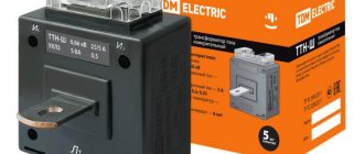
Devices that proportionally convert alternating current from one quantity to another based on the principles of electromagnetic induction are called current transformers (CTs).
They are widely used in the energy sector and are made in different designs, from small models placed on electronic boards to meter-long structures installed on reinforced concrete supports.
The purpose of the test is to identify the performance of the CT without assessing the metrological characteristics that determine the accuracy class and angular phase shift between the primary and secondary current vectors.
Possible faults
. Transformers are made as autonomous devices in an insulated housing with leads for connection to primary equipment and secondary devices. Below are the main causes of malfunctions:
— damage to the housing insulation; — damage to the magnetic circuit; — damage to the windings: — breaks; — deterioration of conductor insulation, creating interturn short circuits; — mechanical wear of contacts and leads.
Test methods
. To assess the condition of the CT, a visual inspection and electrical tests are carried out.
Visual external inspection
. It is carried out first and allows you to evaluate:
— cleanliness of the external surfaces of parts; — the appearance of chips on the insulation; — condition of terminal blocks and bolted connections for connecting windings; — presence of external defects.
Insulation check
. (operation of CTs with damaged insulation is not allowed!).
Insulation tests
. On high-voltage equipment, the current transformer is mounted as part of the load line, enters it structurally and is subjected to joint high-voltage testing of the outgoing line by insulation service specialists. Based on the test results, the equipment is allowed into operation.
Checking the insulation condition
. Assembled current circuits with an insulation value of 1 mOhm are allowed for operation.
To measure it, a megohmmeter with an output voltage that meets the requirements of the CT documentation is used. Most high voltage devices should be tested with a 1000 volt output meter.
So, a megohmmeter measures the insulation resistance between:
- housing and all windings; - each winding and all the others.
The performance of a current transformer can be assessed by direct and indirect methods.
1. Direct verification method
This is perhaps the most proven method, which is also called checking the circuit under load.
A standard CT switching circuit is used in the circuits of primary and secondary equipment, or a new test circuit is assembled, in which a current from (0.2 to 1.0) of the rated value is passed through the primary winding of the transformer and measured in the secondary.
The numerical expression of the primary current is divided by the measured current in the secondary winding. The resulting expression determines the transformation coefficient and is compared with the passport data, which allows us to judge the serviceability of the equipment.
A CT may contain several secondary windings. All of them, before testing, must be reliably connected to the load or short-circuited. In an open secondary winding (with current in the primary), a high voltage of several kilovolts arises, dangerous to humans and equipment.
The magnetic cores of many high-voltage transformers require grounding. For this purpose, a special clamp marked with the letter “Z” is equipped in their terminal box.
In practice, there are often restrictions on testing CTs under load related to operating and safety conditions. Therefore, other methods are used.
2. Indirect methods
Each method provides some information about the state of the CT. Therefore, they should be used in combination.
Determining the reliability of winding terminal markings
. The integrity of the windings and their output is determined by “continuity testing” (measuring ohmic active resistances) with checking or marking. Identification of the beginnings and ends of the windings is carried out in a way that allows the polarity to be determined.
Determining the polarity of winding terminals
. First, a milliammeter or voltmeter of the magnetoelectric system with a certain polarity at the terminals is connected to the secondary winding of the CT.
It is possible to use a device with a zero at the beginning of the scale, however, it is recommended to use one in the middle. All other secondary windings are bypassed for safety reasons.
A direct current source with a resistance limiting its discharge current is connected to the primary winding. An ordinary flashlight battery with an incandescent light bulb is sufficient. Instead of installing a switch, you can simply touch the wire from the light bulb to the primary winding of the CT and then remove it.
When the switch is turned on, a current pulse of the corresponding polarity is formed in the primary winding. The law of self-induction applies. When the winding direction in the windings coincides, the arrow moves to the right and returns back. If the device is connected with reverse polarity, the arrow will move to the left.
When the switch is turned off for unipolar windings, the arrow pulses to the left, and otherwise to the right.
In a similar way, the polarity of the connections of other windings is checked.
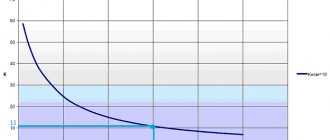
Removing the magnetization characteristic
. The dependence of the voltage at the contacts of the secondary windings on the magnetizing current passing through them is called the current-voltage characteristic (CVC). It indicates the operation of the CT winding and magnetic circuit and allows you to assess their serviceability.
In order to eliminate the influence of interference from power equipment, the current-voltage characteristics are taken with an open circuit at the primary winding.
To check the characteristics, you need to pass alternating current of various sizes through the winding and measure the voltage at its input. This can be done by any testing stand with an output power that allows loading the winding until the CT magnetic circuit is saturated, at which point the saturation curve goes horizontal.
The measurement data is entered into the protocol table. Graphs are drawn from them using the approximation method.
Before starting measurements and after them, it is necessary to demagnetize the magnetic circuit by several smooth increases in current in the winding, followed by a decrease to zero.
Abnormal transformer secondary voltage
The transformer primary voltages are the same and the secondary voltages are the same at no-load, but vary greatly under load.
Causes:
- poor contact in the connection of one terminal or inside the winding of one phase;
- break in the primary winding of a rod-type transformer connected according to a delta-star or delta-delta circuit.
The primary voltages of the transformer are the same, but the secondary voltages are not the same at no-load and at load.
Causes:
- the beginning and end of the winding of one phase of the secondary winding are mixed up when connected by a star;
- a break in the primary winding of a transformer connected according to a star-star circuit. In this case, the three linear secondary voltages are not zero;
- a break in the secondary winding of the transformer when connecting it according to the star-star or delta-star circuit. In this case, only one line voltage is not zero, and the other two line voltages are zero.
With a delta-delta connection circuit, a break in its secondary circuit can be determined by measuring resistance or by heating the windings: the winding of the phase that has a break will be cold due to the lack of current in it. In the latter case, temporary operation of the transformer is possible at a current load of the secondary winding of 58% of the rated one. To eliminate faults that cause symmetry violations in the secondary voltage of the transformer, repair of the windings is necessary.
Source: Electrician School
17428
Bookmarks
Comment 2
Latest publications
Experts from the National Research University "MPEI" discussed the future of engineering education at the Rosatom project session
July 30 at 13:35 28
IPPON at the video surveillance industry event Layta Connect in Kazan
July 29 at 17:27 28
Rockwell Automation presented a film episode about digital transformation with Technologies Added and Sustainder
July 28 at 23:42 38
The SME Corporation will launch a new “umbrella” guarantee mechanism for small businesses in August
July 28 at 23:40 34
"Samsung IT Academy" begins work at the Moscow Energy Institute
July 28 at 23:32 40
Schneider Electric Wins Project of the Year Award for Supply Chain Initiative
July 28 at 23:29 28
The manufacturer of specialized pipes invested 200 million rubles in the development of the enterprise with the support of PSB and the SME Corporation
July 27 at 18:18 44
Congratulations to the Bashkir Generating Company on its 15th anniversary
July 27 at 16:01 38
The unique experimental power plant of the National Research University "MPEI" received a positive conclusion from the state examination
July 27 at 14:44 71
A new point on the map of the Far Eastern projects of ZETO CJSC - a catering center for the seaport of Sukhodol
July 26 at 15:54 42
Comments 2
Zakharov O.G.
https://infra-e.ru/products/searchdefectrelaycontactorcircuits - read about checking transformer windings here
June 23, 2021 at 12:07
Bookmarks
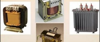
Basic information about transformers
To convert alternating voltage ratings, special electrical machines—transformers—are used.
A transformer is an electromagnetic device designed to convert alternating voltage and current of one magnitude into alternating current and voltage of another magnitude.
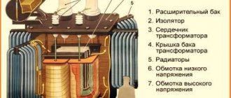
Device and principle of operation
It is used in all consumer power supply schemes, as well as for transmitting electricity over long distances. The transformer design is quite primitive:
- The ferromagnetic core is made of a ferromagnetic material and is called a magnetic core. Ferromagnets are substances that have spontaneous magnetization; the parameters (atoms have constant spin or orbital magnetic moments) vary greatly due to the magnetic field and temperature.
- Windings: primary (mains voltage is connected) and secondary (power supply to a consumer or group of consumers). There can be more than 2 secondary windings.
- Additional components are used for power transformers: coolers, gas relays, temperature indicators, moisture absorbers, current transformers, protection systems and continuous oil regeneration.
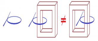
The principle of operation is based on the conductor being in an alternating electric field. When a conductor moves, for example, a solenoid (coil with a core), a voltage can be removed at its terminals, which depends directly proportionally to the number of turns. This approach is implemented in a transformer, but it is not the conductor that moves, but the electric field formed by alternating current. It moves along a magnetic circuit made of ferromagnet. Ferromagnetic is a special alloy ideal for the manufacture of transformers. Basic materials for cores:
- Electrical steel contains a large mass fraction of silicon (Si) and is combined under high temperature with carbon, the mass fraction of which is no more than 1%. Ferromagnetic properties are not clearly expressed, and eddy current losses (Foucault currents) occur. Losses increase directly proportionally with increasing frequency. To solve this problem, Si is added to carbon steel (E42, E43, E320, E330, E340, E350, E360). The abbreviation E42 stands for: E - electrical steel containing 4% - Si with 2% magnetic losses.
- Permalloy is a type of alloy and its constituent parts are nickel and iron. This species is characterized by a high value of magnetic permeability. Used in low-power transformers.
When current flows through the primary winding (I), a magnetic flux F is formed in its turns, which propagates along the magnetic circuit to winding II, as a result of which an EMF (electromotive force) is formed in it. The device can operate in 2 modes: load and idle.
Transformation coefficient and its calculation
Transformation ratio (k) is a very important characteristic. Thanks to it, you can identify malfunctions. The transformation ratio is a value showing the ratio of the number of turns of winding I to the number of turns of winding II. According to k, transformers are:
- Decreasing (k > 1).
- Raising (k