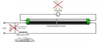
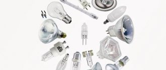
Despite the advent of LEDs, there are still quite a large number of luminaires with pin-type fluorescent lamps in use. They also allow you to spend less on electricity, especially if the lamp uses electronic ballast - electronic ballasts for fluorescent lamps.
Electronic ballast (electronic ballast, electronic ballast) is an electronic device that starts and maintains the operating mode of gas-discharge lighting lamps.
How does a fluorescent lamp with a choke work?
Emballast is an electromagnetic ballast or simply a “choke”. Having understood the principle of operation of electronic ballasts, it will be easier to understand the structure and operating principle of electronic ballasts.
First, it’s worth understanding how a fluorescent lamp works. We will talk about long lamps like T-8. In addition to the light source, there is also a starter (discharge lamp) and a ballast (inductor and capacitors).
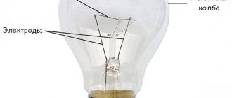
Fluorescent lamp design
Fluorescent lamp: device and operating conditions
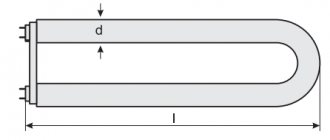
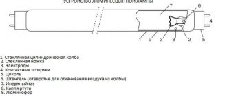
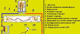
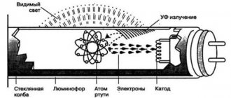
A few words about tubular-type fluorescent lamps. This is a hollow glass tube coated on the inside with a layer of phosphor. Metal caps with two pins are placed on the edges of the tube. These pins are the cathode leads. The cathodes are connected in pairs by a tungsten spiral with a special emissive coating. The lamp is filled with a mixture of inert gases and mercury vapor (there is no air inside). In order for the phosphor to light up, it is necessary:
- The presence of an alternating electric field.
- Free charged particles.
Structure of a fluorescent lamp
In the presence of an alternating field, electrons and ions actively move, colliding with the walls of the bulb, thereby causing the phosphor applied to them to glow. Everything seems simple. But when turned on, it is necessary to create conditions for the appearance of free charged particles in an inert environment. When turned off they are simply not there. And even if 220 V is directly applied to the cathodes, nothing will happen. There will be an alternating electric field, but there will be no unbound ions and electrons. And there will be no light either.
How to make a fluorescent lamp glow
So, in order for the lamp to light up, it is necessary that free charged particles appear in it. There are two ways to initiate their release:
- briefly apply high voltage to the cathodes (cold start);
- heat the spiral between the two cathodes to the temperature at which emission begins.
How to make a phosphor glow
Usually the second option is used. It requires more time and energy, but the lamps themselves “live” longer. Cold starting is popular among do-it-yourselfers. But this method “rips” particles out of the structure, which leads to rapid failure of the lamp. What's good about it is that you can make lamps with burnt-out filaments work. But it is irrational to use it, since the cathodes quickly burn out.
How does a fluorescent lamp work with EMPA (electromagnetic ballast)
In order to ensure the appearance of free particles, a choke is used, which is also called electromagnetic ballast and a starter. To stabilize operation, capacitors are used (in the diagram below C1 and C2). The choke is a set of ferromagnetic plates wrapped in enameled copper wire. A choke is similar to a transformer, only it has one winding. The starter is a gas-discharge lamp with a movable bimetallic contact.
Block diagram
While the lamp is cold, tungsten has a high resistance, therefore, when turned on, the current flows weakly - about 35-50 mA. It is not enough to heat the cathodes, but it is sufficient to operate the starter gas-discharge lamp. The current flowing through the starter heats the contacts of the gas-discharge lamp. As the bimetallic contact heats up, it bends and at some point comes into contact with the second, fixed contact. At this moment, the current instantly increases to hundreds of milliamps (500-800 mA). The glow discharge in the starter goes out, the bimetallic contact cools down and opens the circuit. But for a few seconds the current in the circuit is very high. This time is enough to heat up the cathodes of the lamp and begin the emission of free particles. A cloud of free ions and electrons forms near the cathodes.
But this is not yet the start of the lamp. It still doesn't light up. When the contact in the starter opens, an electromotive force (EMF) appears in the throttle, which is in phase with the mains voltage. This leads to an instantaneous voltage surge of up to kilovolts (1000 V or more). Such high voltage causes arc ignition, gas breakdown in the lamp and active release of free particles. Particles hitting the phosphor cause it to glow. The lamp lights up.
Disadvantages of EmPRA
At one time, this scheme was popular: electricity costs for lighting were reduced by about two to three times. And this despite the fact that such lamps lasted longer and produced clearer light. But they also have serious disadvantages:
- The lamp does not light when cut off. A few seconds pass. And the longer the life of the lamp, the longer the period of time.
- The light "blinks". We don't see it, but the retina reacts to blinking. This causes increased fatigue and can cause headaches. When working with rotating parts, a stroboscopic effect occurs, which can be dangerous.
- The throttle hums during operation. Some are quite loud. Constant background noise reduces performance.
- In a cold room, the lamp may not light up at all.
- The throttle can heat up to 100°C - this is an additional energy consumption.
Modern electronic ballasts from Schwabe Hellas. Q 125.613.4 - electromagnetic ballasts (EMPPAs) are used with lamps for indoor use with a power of 125 Watts. Sometimes EPGRA is called a choke for fluorescent lamps - take this into account when searching through catalogs
All these disadvantages are eliminated in electronic ballasts (electronic ballasts). Plus, they also consume less electricity, which makes fluorescent lamps more economical.
ECG FOR LED LUMINAIRES AND PANELS
It should be noted right away that ballasts for LED lamps and other LED light sources do not exist! No matter what store sellers or online service consultants claim, this only indicates their incompetence.
LED light sources do not require starting devices such as electronic ballasts. A constant voltage source is required, and ideally a current stabilizer.
Such devices are called drivers. They generate voltage at the output terminals in accordance with the connected light source and limit or stabilize the output current within certain limits.
The fact is that LEDs function normally only in a narrow range of current flowing through them. A lower value reduces the brightness, and a high value causes a sharp decrease in service life up to the instantaneous burnout of the emitting diode. An LED, as a semiconductor element, has a pronounced dependence of the resistance value on temperature, so changing it by just a few degrees can cause a critical increase in current.
What is the difference between a voltage stabilizer and a current stabilizer?
Read also: Cross switch connection diagram
To put it in simple words, a voltage stabilizer has a stable output voltage, despite the fact that the current consumption of connected devices can vary widely.
The situation is different in the case of a current stabilizer. This ensures a stable current value at different load resistances. In this case, the voltage value of the stabilizer can vary over a fairly wide range.
This characteristic imposes a limitation on the compatibility of devices of various types. LED lamps of a power other than that specified in the specification cannot be connected to the current source. You cannot connect several lamps in parallel. As a last resort, a serial connection is possible, but this is only if the output voltage range allows it.
The driver (this is what the current stabilizer is currently called) is designed for an output current of 100 mA and 12 - 24 V output voltage. Can be connected:
- LED lamp 100 mA 12 V or 100 mA 24 V;
- two 100 mA 12 V lamps connected in series;
- two 50 mA 12 - 24 V lamps connected in parallel.
The driver circuit can be made using either a transformer or an inverter, which currently constitutes the vast majority of devices. Drivers with variable output current are used to adjust the brightness of LED lamps.
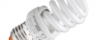
Most compact lamps are available with built-in drivers, freeing the buyer from the agony of choice. The use of separate drivers is only necessary when using LED strips or making luminaires from individual LEDs or matrices.
When purchasing LED panels with fixed dimensions, it is advisable to immediately rely on a driver with the recommended parameters.
© 2012-2019 All rights reserved.
All materials presented on this site are for informational purposes only and cannot be used as guidelines or regulatory documents.
A ballast for fluorescent lamps is a ballast that is used to effectively limit the current.
The use of such ballast is especially important when the electrical load is insufficient and there is no sufficient limitation on current consumption.
Electronic ballasts for fluorescent lamps: selection basics
On store shelves you can find electronic ballasts for fluorescent lamps that are comparable in price to electromagnetic lamps. There is another category - they cost three to four times more. Despite the difference in price, it is better to choose more expensive ones. The price didn't just happen. An expensive electronic ballast has exactly the same structure as shown above - with all the optional devices (power factor correction, brightness control and feedback). Due to this, more expensive electronic ballasts for fluorescent lamps consume significantly less electricity, provide more “even” operating conditions, which extends the life of the lamps. In general, this is the case when it is more economical to buy a more expensive option.
You need to choose according to technical indicators
But price is not all you should pay attention to. The following indicators need to be monitored:
- An electronic ballast is provided for one or two lamps. This parameter is displayed by a picture on the body. It is usually shown how they should be connected.
- Electronic ballast power. It must match the power of the lamps. Otherwise the lamp will not function.
- What lamps does this electronic ballast work with (types of lamps - T4, T5 and T8).
- Housing protection degree IP. If the luminaire is installed in living rooms, the standard design is sufficient - IP23. Bathrooms require increased moisture protection - IP 44 and higher.
For street lamps, the temperature range is important. It is worth noting that not all lamps, and not all electronic ballasts, can operate at low temperatures. It may happen that the lamp simply does not warm up to a temperature sufficient to start. So pay attention to this indicator.
Should I choose electromagnetic or electronic ballasts?
Electromagnetic ballasts (EMG) consist of at least an inductive ballast and a pulsed ignition device (IZD). If the kit includes a compensating capacitor, the efficiency of the EMCG increases.
When purchasing a ready-made lamp with a built-in electrical component, no special skills are required to connect it. But when combining a lamp and an electrical component, special electrical knowledge is required.
The amount of luminous flux and power consumption in luminaires with electromagnetic ballasts depend on the supply voltage. When operating EMPRA, background noise may occur, which can negatively affect the mood of customers. Another disadvantage of EMPR operation is that the real life of the lamp is approximately 2-2.5 times less than the rated one. And finally, lamps with EMPR are quite massive. For example, if the average weight of a luminaire for a 70W lamp is about 2 kg, then for a 400W lamp it is already about 9 kg. As a rule, when installing such a lamp, the EMPR is not suspended together with the lamp, but is installed below at a considerable distance or on special mounts under the ceiling.
EMPRAs are good because they are traditional; they are produced using technology that has been proven over many decades, ensuring decent reliability. The most unreliable element of the EMPRA is the IZU. If you come to terms with the features listed above, then a lamp with EMCG will be relatively inexpensive.
At present, electronic ballasts (ECGs) have become a real alternative to electronic ballasts, whose operational characteristics and operating efficiency are much higher than those of the former.
Electronic ballasts are more expensive compared to electromagnetic ballasts, but the initial costs are offset by their high efficiency, which is characterized by:
- energy consumption reduced by 30% (while maintaining luminous flux) due to increased light output of the lamp at an increased frequency and higher efficiency;
- increased lamp life by 50% due to gentle operation and start-up modes;
- reduction in operating costs due to a reduction in the number of replaced lamps and no need to replace starters;
- additional energy savings of up to 80% when working in light control systems;
- the ability to create light control systems.
Due to rising electricity tariffs, the use of electronic ballasts for fluorescent lamps is becoming more and more feasible. Even at current prices for electronic ballasts, which are 5 to 10 times higher than for electromagnetic ballasts and a starter, electronic ballasts pay for themselves by saving energy and increasing the service life of lamps. Specialists from the largest lighting companies (Osram, Philips, Motorola, etc.) have calculated that at the current level of prices for electricity and devices, the payback period for electronic ballasts is from 1 to 2.5 years, depending on the operating time of the lamps.
Electronic ballast circuits
It hardly makes sense to assemble electronic ballast with your own hands. Even quality models don't cost enough to justify the time required to assemble them. Unless you want to do something yourself. A self-made thing that works certainly brings moral satisfaction. There are a lot of schemes on the Internet, but many of them are completely unworkable. At this point we will present the workers - based on microcircuits or without them.
Electronic ballast circuit for fluorescent lamps based on transistor switches
Electronic ballasts based on the IR2520D chip from IR with an operating frequency range from 35 kHz to 80 kHz
Electronic ballast circuit based on the UBA2021 chip from NXP. Operating frequency 39 kHz
Ballast with ICB1FL02G chip and 40 kHz frequency
Principle of operation
Let's look at what a fluorescent lamp is and how it works. It is a glass tube that begins to work due to a discharge that ignites the gases inside its shell. A cathode and anode are installed at both ends, and it is between them that the discharge occurs, which causes the starting ignition.
Mercury vapor, which is placed in a glass case, when discharged, begins to emit a special invisible light, which activates the work of the phosphor and other additional elements. It is they who begin to emit the light that we need.
Operating principle of the lamp
Due to the different properties of the phosphor, such a lamp emits a wide range of different colors.