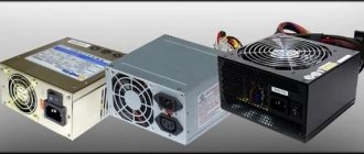
UPS operating principle
The main function of any power supply, including a pulsed power supply, is voltage stabilization in electrical networks. A UPS is a device for rectifying the mains voltage with the subsequent formation of an electrical high-frequency pulse.
Note!
An analog transformer-type power supply unit uses a transformer to change the voltage in the network, which is powered by a 220V power supply. TBP is designed to reduce the voltage in the network.
TBPs are now practically not used in electrical devices due to impracticality and large dimensions.
The differences between a pulse power supply and an analog one are presented in the comparative characteristics table:
| Name | UPS | TBP |
| Design features | Compact size, usually placed inside an electrical device | External power supply, large dimensions and weight |
| Operating principle | Rectifies the primary incoming voltage by converting it into an electrical pulse of a certain frequency | Reduces input voltage, can convert pulsating voltage in one direction to DC |
| Efficiency | About 98%, energy loss is minimal during voltage conversion process | Up to 80%, quite serious energy losses due to high power consumption for operation |
| Electricity losses during operation | Small | High |
| Availability of protection | Available in most existing models | Most models do not have |
| Price | Low, due to the widespread distribution and availability of components | High. Most models are outdated and discontinued, so there is a shortage of spare parts |
The table shows that the advantages of a switching power supply over a transformer are obvious.
Differences between a switching power supply and a regular one
The differences between a switching power supply and a conventional one between transformer and switching, as well as their advantages and disadvantages. For example, a transformer power supply, which contains a transformer that performs the function of lowering the mains voltage to a given one, this design is called a step-down transformer.
Power supplies operating in pulse mode are pulse converters or inverters. In switching power supplies, the alternating voltage at the input is first rectified, and then pulses of the required frequency are generated. Such a power supply, unlike an ordinary power transformer, with the same power, has much less losses and insignificant overall dimensions obtained as a result of high-frequency conversion.
Power supply structures and diagrams
There are two types of UPS: without transformers; PSU with transformer. In transformerless power supplies, the pulse current goes directly to the voltage rectifier. Its circuit is simple and consists of a minimal set of elements: a special integrated circuit and a pulse-width generator. Transformerless power supplies have low power. Since their circuit does not have a galvanic connection to the power supply network, there is a possibility of electric shock.
Note!
Power supplies with a transformer are safer and more reliable. In addition, with their small size, due to the number of turns of the winding, they are able to increase the power of the power supply.
Each turn of the winding has its own voltage rectifier, thus ensuring its output stability. Most desktop PCs use power supplies with power transformers.
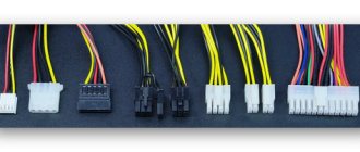
A typical power supply circuit with a transformer consists of:
- line filter with noise suppressor;
- rectifier;
- anti-aliasing filter;
- pulse width converter;
- switch transistors;
- high-frequency transformer at the output;
- output and individual group filters;
- rectifier
Operating principle of a switching power supply
The 220 V voltage is rectified by a bridge with diodes D26-D29. The input capacitors C18 and C19 charge to a total voltage of 320V, and since the inverter operates in a half-bridge system, they divide them in half, resulting in 160V per capacitor. This voltage is further balanced by resistors R16 and R17. Thanks to this separation, it is possible to connect transformer T1 to one channel. The potential between the capacitors is then treated as ground, one end of the primary winding is connected to +160 V, the other to -160 V. The switching voltage of the primary winding of transformer T1 is carried out using a variable N-MOSFET transistor Q8 and Q9.
Capacitor C10 and the primary winding of current transformer T3 are located in series with the primary winding. The coupling capacitor is not needed for the operation of the circuit, but it plays a very important role - it protects against unbalanced energy consumption from the input capacitors and, therefore, before charging one of them to more than 200 V. The current transformer T3, also located in series with the primary winding, acts as short circuit protection. The current transformer provides galvanic isolation and allows you to measure the current value, reduced to the accuracy of its transmission. Its task is to inform the controller about the amount of current flowing through the primary winding T1.
The power MOSFETs cannot be driven directly from the controller due to the change in the potential of the upper transistor source. The transistors are controlled using a special transformer T2. This is an ordinary pulse transformer operating in push-pull mode, opening power transistors. The control transformer T2 has at the input a set of voltage control elements on the windings, which, in addition to generating the voltage dictated by the controller, protect against the occurrence of core demagnetizing voltage. An uncontrolled demagnetization voltage would keep the transistor open. The elements directly responsible for eliminating the demagnetization voltage are diodes D7 and D9, as well as transistors Q3 and Q5. During idle time, when both MOSFETs are off, current flows through D7 and Q5 (or D9 and Q3) and maintains the demagnetization voltage around 1.4 V. This voltage is safe and cannot open the power transistor.
Voltage oscillogram at MOSFET inputs:
On the oscillogram you can clearly see the moment when the core stops being demagnetized by diodes D7 and D8 (D6 and D9) and begins to be magnetized in the opposite direction by transistors Q3 and Q4 (Q2 and Q5). During the core demagnetization phase, the voltage at the T2 gate reaches 18 V, and during the magnetization phase it drops to approximately 14 V. Why is one of the IR type drivers not used? First of all, the control transformer is more reliable, more predictable. IR drivers are very capricious and error prone.
An alternating voltage is generated on the secondary winding of the main transformer T1, so it needs to be rectified. The role of the rectifier is played by rectifying fast diodes, generating a symmetrical voltage. The output chokes are located behind the diodes - their presence affects the efficiency of the inverter, suppressing the surges that charge the output capacitors when one of the power transistors is turned on. Next are the output capacitors with preload resistors, which prevent the voltage from rising to too high values.
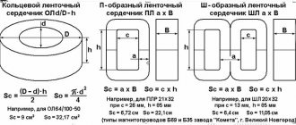
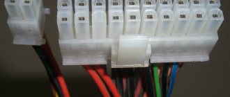
Power supply with power transformer
There are two types of power transformers for UPS: with and without an oblique. Both types can be used for installation in switching power supplies.
A transformer with a braid consists of three windings, the primary circuit is 1 winding, consisting of two half-windings of 20 turns each, and the secondary circuit also consists of 2 half-windings, which are connected in a braid. Each half-winding consists of seven turns, connected in series according to an electrical circuit, each turn is equal to 1 Volt. Connecting windings in series increases power.
The use of power transformers for a switching type power supply is due to a number of advantages:
- series connection of the transformer windings ensures voltage stability in the unit;
- ease of assembly and accessibility of elements;
- the ability to increase the current power due to the number of windings;
- low power consumption.
Power transformers have the following disadvantages:
- if the connections on the spit are not properly insulated, a short circuit may occur;
- electromagnetic field induction may cause interference.
Other options for switching power supplies
What other power options are there for a 12-volt screwdriver? The first thing that comes to mind is a power supply from a laptop. The beauty of the solution is that, unlike the proposed drivers and electronic transformers, such power supplies can be either 15 or 19 V. That is, by choosing the appropriate power supply, you can power a 14 and 18 V instrument with it.
Unfortunately, this option will not work, since the power supplies from the laptop will not be able to provide the necessary current to even the simplest and low-power screwdriver. The maximum you can get from them is 4–5 A. Ten-amp power supplies of this type simply do not exist.
This fairly powerful power supply for a 19-volt laptop will produce a current of no more than 4.75 A
Using universal power supplies
What other options do we have? You can use so-called universal power supplies to power the screwdriver. In the photo below, the power supply produces several voltages at once and is suitable for powering both 12-volt and 18-volt tools with a power of up to 120 watts.
Powerful universal switching power supply
But here again it all comes down to price. The cost of such a power supply will be higher than the price of the tool itself, and in addition, for this money we get a bunch of adapters that will lie around idle.
Homemade power supply for a screwdriver
If we have knowledge of electronics, we can assemble a switching power supply for a screwdriver with our own hands - there are many corresponding circuits. As an example, consider a relatively simple design.
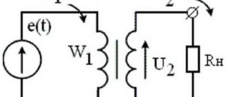
How does it work? The mains voltage is rectified by a diode bridge assembled on diodes VD1–VD4, smoothed by capacitor C1 and supplied to a powerful push-pull self-oscillator assembled on field-effect transistors VT2, VT3 and transformer T1, which, together with winding 2 of transformer T2, provides positive feedback to the self-oscillator.
The circuit assembled on transistor VT1 ensures the initial start of the generator and after that does not participate in the process - it is blocked by diode VD8. The load of the self-generator is the step-down transformer T2. The reduced voltage from its winding 3 is rectified by bridge VD7, smoothed by capacitor C5 and supplied to the instrument. The capacitor capacity is chosen to be large enough to ensure a high starting current for the screwdriver.
T1 is wound on a ferrite ring of size 12x8x3. All windings are the same and have 20 turns of PEV 0.33 wire. T2 is wound on a 40x25x11 ring. Winding 1 has 100 turns of PEV 0.54 wire. Winding 2 - 9 turns of PEV 0.33 wire, winding 3 - 13 turns of PEV 0.96 wire. Ferrite comes in grades 1000NM, 2000NM or 3000NM. The VD4 diode bridge can be assembled using four high-speed diodes that can withstand a current of 10 A. Transistors VT2 and VT3 must be installed on radiators.
Healthy! The proposed power supply is designed for an output voltage of 18 V. If you need to obtain a different voltage, it is enough to change the number of turns of winding 3 of transformer T2.
UPS operation algorithm
The operating principle of the UPS is simple: the input voltage is rectified and converted into electronic high-frequency pulses. At the output, the electrical circuit generates an OOS signal, which regulates the pulses.
The advantages of using a pulse power supply are obvious:
- small size and weight;
- low power consumption;
- ease of assembly;
- low energy losses;
- high efficiency;
- availability of protection;
- low price for components.
The disadvantages of using UPS include the presence of electromagnetic interference due to their operation on high-frequency pulses.
In personal stationary computers, as a rule, a UPS with a power transformer is used. To operate, the power device uses the properties and principles of electromagnetic induction. This makes it possible to transmit current without significant losses over long distances.
Operating principle of the charger
To understand the advantages and disadvantages of two fundamentally different types of chargers, you should consider how a pulse charger differs from a regular one. Although in this context it is not entirely correct to call transformer devices ordinary, because it is actual to call pulse analogues as such.
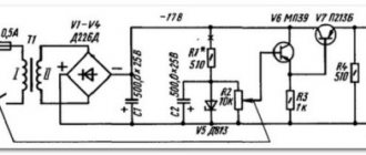
Transformer charger
Such devices are the simplest power supply with a fixed output voltage. Adjustment according to the LATR principle is possible.
The circuit is based on a step-down transformer that produces about 12V AC output. Next, the signal needs to be rectified, for which a diode bridge is used. After the bridge we get direct current in the form of half cycles. In principle, this is already enough to charge a car battery. It would be more correct, of course, to filter the received signal using a capacitor to obtain a smooth straight line.
As you can see, the circuit is very simple and anyone can assemble it from components of old household appliances and electronics.
Pulse charger
Switching power supplies are much more modern devices than their transformer counterparts. Here, too, the AC electrical signal is rectified, but the process is significantly different due to a completely different approach.
The alternating current is rectified and filtered, but instead of being directly reduced, the signal is converted into high-frequency pulses. This justifies the name of such power supplies. This can be followed by galvanic isolation in the form of a pulse transformer. The output voltage will depend on the duty cycle of the pulses (duty factor is the duration of each pulse).