Possible PSU malfunctions
The use of a proven pulse converter circuit for many years has made it extremely reliable.
Therefore, most PSU malfunctions in personal computers are associated either with the aging of its components, or with significant deviations of the power supply or load from the nominal parameters. Separately, it is worth mentioning the overheating of the output stages due to the accumulation of dust inside the power supply due to insufficient frequency of computer maintenance.
Aging has the greatest impact on the condition of the electrolytic capacitors of the rectifier and output stages. Over time, they degrade, losing capacity, which leads to a noticeable increase in voltage ripple at the output of the unit, which can lead to malfunctions of the PC. Also, especially in cheap units, the aging of electrolytic capacitors is accompanied by their noticeable swelling, sometimes leading to their destruction with a characteristic pop.
A significant increase in supply voltage or excessive load can lead to overheating and a short circuit inside the diode bridge of the input rectifier. In this case, alternating current from the network enters circuits that are not designed to work with it: electrolytic capacitors designed for unipolar power supply are destroyed, the PWM controller and its transistor wiring are damaged. Often, damage to the power supply makes its repair less cost-effective compared to a complete replacement.
Failure of the output transistors of a pulse converter is most often a consequence of their prolonged overheating caused by overload or insufficient cooling.
Diagnosis and simple repairs
A person planning to try to repair the power supply of household electronic equipment must be prepared in advance for the fact that not every power supply can be repaired. Today, some manufacturers produce electronics whose units are not subject to repair, but complete replacement.
No technician will undertake the repair of such a power supply, because it was originally intended for the complete dismantling of the old device and replacement with a new one. Often such electronic devices are simply filled with some kind of compound, which immediately removes the question of its maintainability.
Statistics show that the main malfunctions of the power supply are caused by:
- malfunction of the high-voltage part (40.0%), which is expressed by breakdown (burnout) of the diode bridge and failure of the filter capacitor;
- breakdown of a power field-effect or bipolar transistor (30.0%), which generates high-frequency pulses and is located in the high-voltage part;
- breakdown of the diode bridge (15.0%) in the low-voltage part;
- breakdown (burnout) of the output filter inductor windings.
In other cases, diagnosing is quite difficult and without special instruments (oscilloscope, digital voltmeter) it will not be possible. Therefore, if the malfunction of the power supply is not caused by the four above-mentioned main reasons, you should not engage in home repairs, but immediately call a specialist for replacement or purchase a new power supply.
Malfunctions of the high-voltage part are quite easy to detect. They are diagnosed by a blown fuse and no voltage after it. The third and fourth cases can be assumed if the fuse is working, the voltage at the input of the low-voltage unit is present, but the input is absent.
If the fuse blows, it is necessary to inspect the electronic board. A malfunction of the filter electrolytic capacitor is usually expressed by its swelling. To check the diodes of the high-voltage rectifier part, you will have to unsolder each of them and check it with a multimeter (tester).
It is advisable to check all parts simultaneously. If several electronic elements burn out when replacing one of them with a working one, it may burn out again due to a complex malfunction that has not been eliminated.
After replacing parts, you must install a new fuse and turn on the power supply. As a rule, after this the power supply starts working.
If the fuse has not blown and there is no voltage at the output of the power supply, then the cause of the malfunction is a breakdown of the rectifier diodes of the low-voltage part, a burnt-out inductor, or the output of the electrolytic capacitors of the secondary rectifier unit.
The malfunction of capacitors is diagnosed when they swell or leak liquid from their housing. The diodes must be unsoldered and checked with a tester in the same way as checking the high-voltage part. The integrity of the inductor winding is checked by a tester. All faulty parts must be replaced.
If you can’t find the right inductor, then some “craftsmen” rewind the burnt one, selecting a wire of a suitable diameter and determining the number of turns. Such work is quite painstaking and is usually performed only for unique power supplies; it is difficult to find an analogue for which.
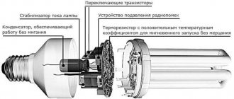
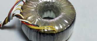
Why do you need to disassemble a transformer?
Pulse transformers are analyzed in two cases:
- Repair or replacement of windings. During operation, due to overload and overheating, as well as vibration, the insulation of the wires is destroyed. This leads to a short circuit and failure of the coil. A separately located secondary winding of several turns can be rewound without disassembling the device, but if it consists of a large number of turns, then it will not be possible to rewind it without disassembling it.
- Changing the number of turns. Pulse transformers and chokes installed in power supplies are manufactured for specific devices and have a certain number of turns and wire cross-section. In homemade devices, the voltage does not always correspond to what was in the original device. In some cases, it is possible to remove the secondary winding and wind a new one, but this does not always work.
TV PSU repair
Before repairing a television power supply, it is useful to acquire its circuit diagram. The operating principle of these power supplies is the same as any other. But it produces multiple output voltages, which makes the diagnostic process a little more complicated.
TV switching power supply circuit
Another difficulty is the presence of several protection systems for Uout deviations. from the norm. Because of them, the symptoms of many breakdowns look monotonous: the power supply does not show any signs of performance at all.
Today, the power supply circuit for almost any TV can be found on the Internet. A failure of the power supply is indicated by the inoperability of the LED, which usually operates in standby mode. If it burns, the cause is sought elsewhere.
As part of the diagnostics, the following elements are checked:
fuse. If there is no voltage behind it, the part is replaced;
ballast resistances. Their breakage is a possible cause of the malfunction;
smoothing capacitors of high-voltage and low-voltage rectifiers. Possible breakdown;
LC filter choke of the low-voltage rectifier. Possible breakage and interturn short circuit. If this model of power supply is rare, and it is not possible to find a similar inductor on sale, it can be rewound independently from a wire of the same cross-section
It is important to maintain the correct number of turns;
rectifier diodes. The semiconductors of the high-voltage converter fail more often because they operate under high voltage
Unlike the radio components listed above, diodes have to be soldered off for diagnostics.
It is impossible to check the functionality of the inverter microcircuit at home. Its malfunction is judged by indirect signs: if the normal state of all other elements is confirmed, but the power supply still does not work.
If the fuse is intact, check the voltage at the output of the high-voltage rectifier, looking for the following parameters:
- meaning;
- ripple amplitude (determined by an oscilloscope).
Normal values are from 280 to 320 V. At low values, the diodes are checked. A high ripple amplitude indicates a faulty smoothing capacitor or a broken rectifier.
If the voltage is normal, check the nature of the malfunction; two options are possible:
- The power supply does not turn on at all;
- tries to turn on, but is turned off by the locking system (reacts to low or high output voltage).
Popular articles Congratulations on March 8th. How to congratulate women on March 8 in an original way
An oscilloscope is used again. Its input is connected to the output of the inverter key transistor connected to the primary winding of the transformer.
Ground the device to the “hot ground” of the power supply. If, when you turn on the TV with the power button, a series of pulses appears on the oscilloscope, this indicates attempts to start. This means that the device is blocked by one of the protections, for example, from exceeding the anode voltage on the kinescope. This helps narrow down the troubleshooting area.
If the power supply does not try to turn on, check the inverter elements. For example, measure the voltage at the collector of a key transistor. It should be the same as on the smoothing capacitor of the high-voltage rectifier.
The absence of voltage indicates a break in the primary winding of the pulse transformer. Having replaced the damaged radio components, they continue checking the power supply by turning on an incandescent light bulb with a power of 100 - 150 W instead of the fuse.
When you activate the power button on the TV, the light bulb behaves in accordance with the adapter malfunction:
- flashes and immediately goes out, the standby mode diode lights up, a raster is visible on the screen. The horizontal scan voltage needs to be checked. If it is too high, check and, if necessary, change capacitors and optocouplers;
- came on and went off, but the LED does not light up, and there is no grid on the screen. This indicates that the inverter is not working. Check the voltage on the smoothing capacitor of the high-voltage rectifier. If the value is too low, as already mentioned, a check of the diodes and this capacitor is required;
- burns especially brightly. In this case, the power supply is immediately disconnected from the network and the functionality of all elements is checked again.
Repair of UPS units of computers and televisions
To repair a pulse voltage source, you will need tools such as a soldering iron with temperature control, a set of screwdrivers, wire cutters, tweezers, a mounting knife, and a regular 100 W lamp. From the material you will need solder, flux, alcohol to remove rosin with a brush from the board solder. The equipment you will need is a multimeter.
Since switching power supplies (UPS) for televisions and computers have standard circuits, the method for detecting faults in them will be the same. A malfunction of the TV's voltage converter can be determined by the absence of LED backlighting.
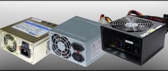
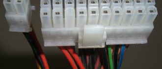
ATX computer power supply
The repair begins by checking the power cord, removing the power supply from the TV, and carefully inspecting the elements and traces of the board. They look for swollen capacitors, darkening of the tracks, cracked casing of alimony, charring of resistances, violation of the integrity of soldering joints, especially at the terminals of the pulse transformer.
If external damage is not found with a multimeter, check the fuse, diodes, power transistors of the keys, and the functionality of the capacitors. When you are sure that all elements are in good working order, but the device does not work, you need to change the pulse generator chip.
In a TV converter, the main faults occur in ballast resistors, low voltage electrolytic capacitors, and diodes. You can ring them without removing them from the boards (except for diodes). After troubleshooting, solder a 100 W lamp instead of the fuse and turn it on.
- The lamp lights up and goes out, and the sleep mode LED lights up. The TV screen lights up. Then check the horizontal voltage; if it is higher than normal, change the capacitors.
- The lamp lights up and goes out, but the LED does not light up, there is no raster. The reason is most likely in the pulse generator. Measure the voltage on the capacitor, which should be in the range of 280 - 300V. If the voltage is lower, the fault is sought in the diodes or in a capacitor leak. If there is no voltage on the capacitor, all circuits of high-voltage power supplies are checked again.
- The lamp burns brightly when some elements are faulty. The voltage source is checked again.
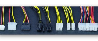
Using an incandescent lamp, you can find possible faults in the source. To repair a computer's ATX source, you need to assemble a load circuit as in the figure below or connect it to a computer. However, if the malfunction of the ATX unit is not corrected, you can burn the motherboard.
Load option for computer power supply
An external manifestation of an ATX unit failure may be when the motherboard does not turn on, the fans do not work, or the unit tries to turn on repeatedly. Before troubleshooting the device, you need to clean it from dust with a vacuum cleaner and a brush. A visual inspection of the elements and board tracks is also carried out, and only after that the load is turned on.
If the fuse blows, then connect a 100 W incandescent lamp, as when checking the voltage source on a TV. When the lamp lights up but does not go out, the fault is looked for in the capacitor, transformer and bridge diodes. If the fuse is intact, a malfunction could occur in the PWM controller, then it is necessary to replace the device. Also, repeated starting of the source indicates a malfunction of the reference voltage stabilizer.
Working tool for testing switching power supplies
To repair a switching power supply, you will need a regular, even simple multimeter that will check DC and AC voltage. Using the functions of an ohmmeter, by ringing the resistance of radio components, you can also quickly check the serviceability of fuses, chokes, the operating resistance of resistors, and the “barrels” of electrolytic capacitors. As well as transistor diode junctions or diode bridges and other types of radio elements and their connections in any electronic circuit (sometimes without even desoldering them completely).
The pulse unit must first be checked in “cold” mode. In this case, all visually suspicious (swollen or burnt radio components) are called up, which can be checked “cold” without applying operating voltage. Visually damaged radio components should be immediately replaced with new ones. If the marking has peeled off, use the circuit diagram or find the appropriate option on the Internet.
Replacement must be made only with a permitting tolerance for certain parameters, which you can find for any radio element in specialized literature or in the diagram supplied with the device. This is a safe method, because switching power supplies are very insidious with their electrical discharges.
Do not forget that if a non-working radio element is detected, you need to check the parts adjacent to it. Often, sudden voltage drops during the combustion of one element lead to the failure of neighboring ones. In the process of practical work on repairing certain models, you will logically calculate the fault based on the result of the condition of the object being repaired. For example, even by a certain smell (the smell of rotten eggs when the electrolyte fails), when turned on, by a monotonous sound or crackling sound during the operation of the unit and other defects that may arise during the operation of any electronic device.
In operating mode, checking a switching power supply is only possible when the entire system is loaded - do not even think about disconnecting the TV’s load buses when checking. You can create a load artificially by connecting a specially assembled load equivalent.
Switching power supply operation
Primary circuit of a switching power supply
The primary circuit of the power supply circuit is located before the pulse ferrite transformer.
There is a fuse at the input of the unit.
Next comes the CLC filter, with the coil used to suppress common mode interference. Following the filter is a rectification circuit based on a diode bridge and an electrolytic capacitor. Often, to protect the circuit from short high-voltage pulses, a varistor is installed after the fuse in parallel with the input capacitor. The resistance of the varistor drops sharply at increased voltage. Therefore, all excess current goes through it to the fuse, which burns, turning off the input circuit.
The protective diode D0 is needed in order to protect the power supply circuit if the diode bridge burns out. The diode will not allow negative voltage to pass into the main circuit, because the fuse will open and burn.
Behind the diode there is a 4-5 ohm varistor to smooth out sudden jumps in current consumption at the moment of switching on and initial charging of capacitor C1.
Active elements of the primary circuit: switching transistor Q1 with a PWM (pulse width modulator) control controller. The transistor converts a direct rectified voltage of 310V into an alternating voltage, which is converted by transformer T1 on the secondary winding into a reduced output.
And one more thing - to power the PWM regulator, the rectified voltage taken from the additional winding of the transformer is used.
Operation of the secondary circuit of the switching power supply
In the output circuit after the transformer there is either a diode bridge or 1 diode and a CLC filter consisting of electrolytic capacitors and a choke.
Optical feedback is used to stabilize the output voltage. It allows you to galvanically decouple the output and input voltages. Optocoupler OC1 and integrated stabilizer TL431 are used as feedback actuators. When the output voltage after rectification exceeds the voltage of the TL431 stabilizer, the photodiode turns on, which turns on the phototransistor that controls the PWM driver. The TL431 regulator reduces the duty cycle of the pulses or stops altogether until the voltage drops to the threshold.
General description of a household switching power supply device
Of course, in order to try not only to repair a switching power supply, but also to determine its malfunction, you must have basic knowledge of electronics and have certain electrical skills.
Popular articles Napkin with embroidered roses
In addition, it should be remembered that some elements of the unit are under mains voltage, so even during the initial inspection of the device, care should be taken. However, most units are built according to standard circuits and have similar faults, so anyone can try to repair a switching power supply on their own. Any power source, be it built-in, like in a TV, or installed as a separate device, like in a desktop computer, has two functional blocks – high-voltage and low-voltage
Any power source, be it built-in, like in a TV, or installed as a separate device, like in a desktop computer, has two functional blocks - high-voltage and low-voltage.
In the high-voltage side, the mains voltage is converted by a diode bridge into constant voltage and smoothed out on a capacitor to a level of 300.0...310.0 volts. Constant, high voltage is converted into pulsed voltage, with a frequency of 10.0...100.0 kilohertz, which makes it possible to abandon massive low-frequency step-down transformers, replacing them with small-sized pulse ones.
In the low-voltage block, the pulse voltage is reduced to the required level, straightened, stabilized and smoothed. At the output of this block there is one or more voltages necessary to power household appliances. In addition, various control circuits are mounted in the low-voltage block to increase the reliability of the device and ensure the stability of output parameters.
Visually, on a real board, it is quite simple to distinguish between the high-voltage and low-voltage parts. The network wires come to the first one, and the power wires come from the second one.
Switching stabilizer in a transistor power supply
Description of the voltage converter
The switching power supply can be in the form of a board or an independent remote module. It is intended, as already mentioned, to reduce and rectify the mains voltage. Its necessity is based on the fact that the standard power supply has a voltage of 220 volts, and for the operation of many household appliances a much lower value of this parameter is required. Today, instead of standard buck-rectifier circuits assembled on the basis of a diode bridge and a power transformer, pulsed voltage conversion power supplies are used.
Note! Despite the presence of high circuit reliability, switching power supplies often break down. Therefore, nowadays it is very important to repair these elements of electrical circuits.
Switching power supply circuit
All types of pulsed power supply (built-in or external to the device) have two functional blocks:
- high voltage. In such a power supply, the mains voltage is converted to DC using a diode bridge. Moreover, the voltage is smoothed to a level of 300.0...310.0 volts on the capacitor. As a result, high voltage is converted into pulsed voltage with a frequency of 10.0...100.0 kilohertz;
Note! This design of the high-voltage unit made it possible to abandon massive low-frequency step-down transformers.
- low voltage. Here the pulse voltage is reduced to an unnecessary level. In this case, the tension is smoothed out and stabilized.
As a result of this structure, at the output of the switching type power supply, several or one voltage is observed, which is needed to power household appliances. It is worth noting that the low-voltage unit can contain a variety of control circuits that increase the reliability of the device.
Switching power supply (board). Colors are shown in the diagram
Since power supplies of this type have a complex structure, their proper DIY repair must rely on some knowledge in electronics. When repairing this device, do not forget that some of its elements may be under mains voltage. In this regard, even when conducting an initial inspection of the unit, extreme caution must be observed. Repair in most cases will not cause complications, because... Switching power supplies have a standard design. Therefore, their faults will also be similar, and do-it-yourself repairs look like a completely feasible task.
Repairing the power supply step by step with photos
The resistor could burn out if its rated power dissipation was exceeded for a long time. The burnt resistor was soldered out, and its seat was cleaned:
To replace a resistor you need to find out its value. To do this, a known-good power supply was disassembled. The indicated resistor turned out to have a resistance of 1 ohm:
Further along the circuit of this resistor, a broken capacitor with position number C6 was discovered, the continuity of which showed its low resistance, and therefore unsuitability for further use:
It was precisely the breakdown of this capacitor that could cause the resistor to burn out and further inoperability of the entire device as a whole. This capacitor has also been removed from its place, you can compare how small it is:
The broken capacitor is comparable to the head of a match; such a small part caused the breakdown of the power supply. Next to it on the board, parallel to it, there is a second similar capacitor, which has survived. Unfortunately, there was no replacement capacitor and all hopes rested on the remaining second capacitor. But in place of the burnt resistor, a resistor with the required resistance of 1 Ohm was selected, but not surface mounted:
This resistor was installed on the seat of the burnt one, the soldering areas were cleaned of flux residues, and the seat of the broken capacitor was varnished for better insulation and to eliminate the possibility of air breakdown of this place:
After a test run, the power supply started working in normal mode and the indicator LED stopped blinking:
Subsequently, the installed resistor was replaced with a surface-mount resistor and a second layer of varnish was applied in place of the removed capacitor:
Of course, it would be ideal to install a second capacitor, but even without it, the power supply works fine, without extraneous noise and flickering of the LED:
After connecting the adapter to the network, the output voltage was measured, it turned out to be within the normal range, namely 11.9 Volts:
At this point, the repair of the device can be considered complete, since its functionality has been restored and it can continue to be used for its intended purpose. It is worth noting that the block is made according to a very good design, which, unfortunately, it was not possible to sketch.
At the moment, a quick external inspection reveals a good mains and output filter, a well-thought-out circuitry for controlling the power transistor and good stabilization of the output voltage. The physical design of the device is also at a high level, the installation is rigid and smooth, the soldering is clean, and precision radio elements are used. All this allows you to obtain a high-quality device with precisely specified parameters and characteristics.
Read more about computer power supply repair
Among the general recommendations for troubleshooting, first of all you should carry out a visual inspection, paying attention to darkened areas of the board or damaged radio elements. If a burnt-out resistor or fuse is detected, it is imperative to ring the nearest parts directly connected to the visually damaged one.
Semiconductors and capacitors in high-voltage circuits are especially dangerous, which in the event of a breakdown can lead to irreversible consequences for the entire device if it is turned on repeatedly without identifying a complete list of damaged components. With correct and careful diagnostics, in most cases everything ends well and the breakdown can be eliminated by replacing the damaged parts with the same serviceable ones or those that are similar in nominal value and parameters.
Video instructions for repairing a switching power supply:
Repair of switching power supplies (repair modules)
$0.5 Product link
Today I want to talk about modules for repairing switching power supplies (hereinafter referred to as UPS). Switching power supplies are quite complex products and they often fail (especially low-quality non-name products). Is it worth repairing them? Not always. Often, if the power supply is not of very high quality and has a standard voltage, it is much easier, faster and cheaper to simply buy a new ready-made power supply or a high-quality board from disassembly (the Chinese often inexpensively sell branded power supply boards from disassembly or after restoration).
I haven't written for a long time. The kupislonica project is non-profit (for this reason, mercantile authors have fled to other resources to write laudatory reviews of products provided free of charge by stores, which is probably for the best). Now this is completely my blog (well, maybe there will be 1-2 more authors). Since I have enough work for which they pay (and not bad) and it comes out of turn, articles have not been written for a long time. But, finally, I decided to resume this thankless task, especially since a lot of information has accumulated for writing articles.
There are times when simply changing the power supply is not so easy or even impossible. For example, if it has several non-standard output voltages, unusual dimensions, or is integrated into the main board of an expensive and/or unique product. In this case, there is no alternative to repair. And repairing a UPS is sometimes difficult and expensive. If there is a problem in the “hot” part, the power transistor usually breaks through, which pulls with it a low-resistance current resistor, a PWM chip, a diode bridge, a fuse, and sometimes a common-mode choke. Taken together, the cost of these parts is already high, and this does not include the time spent on repairs, and time is one of the most expensive resources. It often takes a lot of time to recognize elements, find and buy them or their analogues. Sometimes PWM chips do not have markings or they are worn out and you have to look for a match based on the pins, select options and study datasheets. Sometimes specific microcircuits or mosfets can be difficult to purchase or delivery is very long. When ordering, you can run into re-labeling and, after waiting a couple of months, burn them the first time you turn them on or the first serious load. And the worst situation in my opinion: someone already tried to repair the power supply, “plowed” half of the board, lifted and damaged some of the tracks, replaced some parts (and it’s not a fact that with similar ones and not with similar ones that were at hand ). With this option, the time that will have to be spent on restoring the circuit, finding all the problems, ordering and purchasing parts may exceed all reasonable limits and make repairs unprofitable, even if the client is willing to pay dearly. That's when repair modules come in handy.
They are designed to be built into any UPS after the rectifier, connect to an existing power transformer and ensure the power supply operates normally without touching the “cold” part of the circuit, thereby preserving all the voltages and settings of the power supply being repaired. The cost of such repair modules is low (often lower than the cost of parts that need to be replaced when repairing a UPS) and the repair time is guaranteed to be reduced to tens of minutes.
Help: repair modules appeared quite a long time ago and were intended for repairing TV power supplies. They were built on Gakun controllers and were actively discussed on repair forums. Gakun has become a household name, like Xerox, Jacuzzi, toilet, Bendix, etc. in their time. GAKUN modules cost a lot, from ten dollars and more, but when repairing a TV costing from several hundred to thousands of dollars, such a cost was justified, the modules paid for themselves.
By that time, I was no longer involved in repairing televisions, and when repairing network equipment or other inexpensive equipment, the high cost of repair modules reduced the meaning of repair to zero and GAKUN were not interesting to me. It would have been easier to screw in some TOP or TNY. But I wanted more elegant solutions for repairs, I even started developing a repair module myself on the KA5M63035R microcircuit (I had a dozen of them lying around, so I wanted to put them into use), laying out a printed circuit board, etc. But it didn’t come to a series. The Chinese have launched mass production of several types of repair modules. And even though they are not made perfectly, their price is several times lower than the cost of making it yourself, and this is the decisive factor.
Repair modules vary in power and switching circuit. There are modules that practically do not use the circuit of the unit being repaired at all and require only 5 points for their connection: plus and minus of the high-voltage capacitor, drain mosfet must be removed), plus and minus of the output voltage. The board of such a module contains the PWM controller itself, a powerful MOSFET, a miniature power transformer with a rectifier, a stabilization circuit with an optocoupler, and a trim resistor to set the stabilization voltage.
The power of power supplies that can be repaired using such modules is limited only by the mosfet on the module (can be replaced with the desired one). Such modules cost from $2 and up (initially you can choose one with a mosfet of the required power), they have their drawbacks, but I will write a separate review about these repair modules, they are worth it.
The simplest and cheapest (I took from 50 cents) repair modules consist of a miniature board, a controller with a built-in power transistor and a couple of parts. And I want to talk about them today.
These repair modules are made on the FSDM0465 (or FSDM0565) chip and use the self-supply winding of the standard transformer of the power supply being repaired and its optocoupler, thereby assuming that the voltage control circuit of the power supply being repaired is working.
What does the microcircuit promise us?
Features ■ Internal Avalanche Rugged SenseFET ■ Advanced Burst-Mode Operation Consumes under 1W at 240VAC and 0.5W Load ■ Precision Fixed Operating Frequency: 66kHz ■ Internal Startup Circuit ■ Improved Pulse-by-Pulse Current Limiting ■ Over-Voltage Protection (OVP) ■ Overload Protection (OLP) ■ Internal Thermal Shutdown Function (TSD) ■ Abnormal Over-Current Protection (AOCP) ■ Auto-Restart Mode ■ Under-Voltage Lock Out (UVLO) with Hysteresis ■ Low Operating Current: 2.5mA ■ Built-in Soft -Start
As for me, that’s very good. Some sellers on their pages promise power up to 180W. The datasheet for FSDM0465 is not so optimistic, the power is indicated up to 56W. The modules on FSDM0565 are the same, but the power is up to 80W.
It makes sense to pay attention to this when purchasing. Sometimes it is more profitable to buy 2-3 cents more expensive but have one and a half power reserves.
These modules arrived directly on a common board. If you need it, break it off and use it.
This suggests that it’s unlikely that anyone tests them before selling them, so they’re soldered and off they go. The fact that this is not an industrial production is also indicated by the fact that microcircuits with completely different markings, production dates and even different styles of laser markings are sealed on a common board (it is not a fact that among the dozen normal ones there are not 1-2 over-marked and non-working ones). But I haven’t come across any non-working ones yet.
Besides the PWM chip with a built-in power transistor, there are only a couple of parts and a multi-colored cable. I do not rule out that the color of the wires may differ among different basement manufacturers, so you need to double-check and not rely on the description of the connection only by color, especially since some sellers have a blue wire in the description, which is actually white. Probably the description was taken from someone else's page.
Figuring out what to connect where is not that difficult. But this is if the seller kindly posted on his page a schematic diagram of the power supply indicating the connection points.
Something like this. But this is not the best instruction. Sellers often do not understand what they are selling and post pictures that steal from competitors. Look carefully.
Some have a text description. Google translation from Chinese to English and then from English to Russian is difficult to understand, at least I did not rely on it. It’s easier to search through the pages of similar products from other sellers, especially if the product is sold at a higher price. There is a possibility that for a product at a higher price, the seller spent a little more time on the description and perhaps attached a connection diagram.
Like this. Well, that's another matter! Everything is clear right?
Or like this.
For those who speak English, the following picture will be useful:
I made a simple table:
| Wire color | Purpose |
| Green | +320V (“plus” of the high-voltage capacitor) |
| Yellow | Mosfet drain (Drain), transformer |
| Red | Self-powered PWM |
| White | FB with optocoupler |
| Black | Common wire (“minus” of the high-voltage capacitor) |
And here is my approximate diagram of a conditional power supply with colored dots where to connect what.
With the help of this type of repair units, I returned to operation several expensive devices that seemed too heavy to lift, since at different times they went through several repairmen with varying degrees of crookedness and there was no living space on the boards of the built-in power supply units.
But let's get down to business, I'll show you in practice how to restore a dead UPS.
I received the remains of a power supply from a DELL laptop from a service center (I didn’t take a photo before restoration, and what can I see there?) with a classic fault: a broken power transistor, a low-voltage resistor at the source, a diode bridge, a common-mode choke, a fuse and a PWM controller . In short, everything that could burn out burned out. The service found faulty elements and considered that repairing such a power supply did not make sense, so the capacitors were removed from the board, the Schottky diode, common mode choke was replaced with jumpers (probably at the very beginning, when there was hope to fix it), and a microcircuit (with a body kit) responsible for the ID signal soldered out and probably moved to another block. It is strange that the high-voltage capacitor remained in place and turned out to be serviceable. I received the payment in such a deplorable state. But the transformer was in place, the TL431 chip in smd design and its wiring visually seemed untouched, and this gave us hope.
The service team did not solder it carefully, there was clearly no intention of restoring the block, and the board was initially coated with sealant, all together this presented a “heartbreaking sight,” as the donkey from the famous children’s cartoon said. In the place where there should be PWM on the board, several tracks of different lengths are torn off, many SMD parts are missing. Of course, it makes no sense to restore such a power supply in the classical way (search for PWM and replace all parts), the cost of such a repair will be commensurate with the price of a new power supply (especially since the ID chip is no longer there). But with the help of a repair module for $0.5, you can try to get a working power supply with good characteristics. Initially, I set myself the goal of restoring this UPS from what was available, without purchasing anything additional for money; the cost of repair should not exceed the cost of the repair module (50 cents or 1 Belarusian ruble). And I succeeded.
First of all, I soldered the diode bridge. We couldn’t find a suitable one in terms of dimensions, so we had to take it with a power reserve from a computer power supply, slightly bending the leads and widening the holes in the board. Nothing, no more, no less. I soldered the missing capacitors in the secondary circuit (then I will bridge them with ceramics). In terms of voltage, I took it with a reserve, fortunately I had previously ripped out several boards from old CRT monitors and free capacitors; there’s a whole box worth of them. I also soldered the missing dual Schottky diode at 50 volts 45A (there is also a pile after repairs of computer power supplies). I will return to this diode a little later in more detail. Using a tester, I checked that there was no short circuit at the output. There was a specific fuse on the board, a small square one in a plastic case. I don't have any of these in stock. Instead of a fuse, I soldered an NTC thermistor. It should limit the inrush current of the capacitor when connected to the network. I will carry out the tests at the stand, where there is already a transformer decoupling from the network, a plug-in current-limiting light bulb and fuses. When I send this UPS into operation, I will solder a fuse in place of one half of the common-mode choke (now there are just jumpers there). I know that the common-mode choke in the circuit is not superfluous, but it was tiny on the board, it’s unlikely that with a couple of turns it seriously filtered something, rather it simply created an appearance. And most importantly, I don’t have this standard size in stock, and half of the Chinese blocks don’t have them at all. The presence of NTC prevents sparking when turned on and burning of the contacts of the plug and socket, in my opinion this is more important. Next, I unsoldered and checked the optocoupler. There have been cases when, due to a faulty optocoupler, power supplies did not work properly or even failed. The optocoupler turned out to be working. Next, instead of an optocoupler, I temporarily soldered a red LED and connected a laboratory power supply to the UPS output, set the current limit (just in case) and began to gradually increase the voltage. When it reached 19.4 V the LED lit up. This indicates the serviceability of the voltage stabilization circuit.
Next, I unsolder the LED, solder the optocoupler in place and begin connecting the repair module. There was no need to desolder anything else from the board (“everything was already stolen before us…”), the wiring parts of the PWM chip remained on the board, they will not participate in any way in the further operation of the power supply.
I figured out the place where the repair module would be located and shortened the wires and pins of the microcircuit protruding from the back of the repair module board. Next I soldered it by color according to the table.
I turned it on via a light bulb, the LED at the output lit up, the measurement showed that the output voltage was 19.4 V. I turned it off and touched the elements. Everything is cold. Well, it's time to load the power supply a little. As a load, I soldered a 20W car lamp to the output. The lamp is 12-volt, but nothing will happen to it over a short period of time even at 19V. I turn it on, the 12-volt lamp lights up brightly. But after 30-40 seconds it starts blinking and after another couple of seconds it goes out completely. I disconnect the unit from the network, touch the parts: the controller on the repair module is hot, the Internal Thermal Shutdown Function (TSD) has clearly worked. The output Schottky diode is abnormally hot. Obviously, there was a short circuit here.
I unsolder the light bulb, measure the output, and it is short circuit. One half of the dual diode is broken. But the diode is 45 ampere and the current through it was small, a little more than an ampere, it shouldn’t get very hot at that current. And this is where I start to remember, where did I get this diode? Was it not from the box into which I dumped questionable parts taken from computer power supplies that were disassembled? But the diode was working properly, I tested it with a multimeter and inserted it into an electronic radio component tester. Everything was OK! Is such a test enough to be completely sure that the diode is working properly? What about leaks? How will it behave under load with pulsating currents?
From the same box I take another similar dual diode with the same marking (obviously from the same batch), and with a multimeter in diode testing mode it rings as good. I set the multimeter to measure resistance to the limit of 20KOhm. The diode shows conductivity in both directions, in the forward direction 2-3 kOhm, in the reverse direction about 10-15 kOhm. It shouldn't be this way.
If the controller did not have so many different protections, it is possible that such work under load could end in a bang. Plus for the repair module!
I take a new, known-to-be-good diode; it does not ring in the opposite direction at this measurement limit. Now everything becomes clear. Either the diodes were tired, or they were from a defective batch. I solder a new diode into the UPS board and turn it on again.
Everything works, there is a slight heating under load, but it is within normal limits, especially since later both the PWM chip with the power element and the Schottky diode will be on the radiators. The test run showed quite stable operation. There is no case or radiators for this power supply yet, perhaps it will be used as a replacement for some burnt-out power supply, for now I’ll just put it aside until better times.
Conclusions: these repair modules have a low price. They are easy to install and do not require adjustment. They have many different protections, are galvanically isolated from secondary circuits and are safe for equipment. Often they can be just a lifesaver when repairing power supplies of some unique equipment.
I ordered a couple dozen more for myself, let them be in reserve.
PS today I found this interesting branded power supply, also from a laptop, and someone has already tried to repair it.
Some parts in the PWM harness are missing, the rest is all in place.
This will clearly be the next candidate for the introduction of a repair module.
Here are some more links to the same modules: link1, link2.
More powerful module: link.
A more powerful and more versatile module with voltage adjustment: link
Share on social media networks
You might be interested:
Universal charger with USB port
Adapter from microSD to N
Good ceramic knives.
Arduino Pro Mini + CP2102 – USB-UART converter
1602 I2C LCD indicator (display) from YwRobot
Load distribution on the power supply
Since each power supply output voltage is used by a different load, depending on the computer configuration, the current consumption in each branch of the power supply may vary.
Therefore, for each block, in addition to the total maximum power, the maximum current consumption for each output voltage is also indicated.
Using the above photograph as an example, we will demonstrate the principle of calculating the applicability of a power supply:
- The 3.3V circuit has a maximum load current of 27A (89 W);
- A 5V circuit can deliver current up to 26A (130W);
- The 12V circuit is rated for current up to 18A (216 W).
But, since all these circuits are powered from the windings of a common transformer, their total consumption is limited: if in theory the maximum load at voltages of 3.3V and 5V can reach up to 219 W, it is limited to 195 W. With a maximum theoretical current output of all three circuits of 411 W, the actual load is limited to 280 W.
Thus, when adding new hardware to your PC, you need to consider not only the overall power consumption, but also the balance of the electrical circuits. Especially often, replacing power supplies with more powerful ones is required when installing high-performance video cards that significantly load the 12V circuit, while most of the PC power is taken from low-voltage circuits - the high voltage reserve remains insufficient.
Popular articles Unusual Valentine card
Current trends in power supply architecture
Dividing the load into approximately equal parts is nothing more than a trick that the developers successfully used - powering an indivisible load that consumes more than 20 amperes via the +12 volt line is impossible without violating safety standards. Obviously, compliance with these standards depends not only on the separation of channels in the power supply, but also on the layout of power circuits in the load.
If a high-power consumer (for example, a video adapter) that has more than one auxiliary power connector connected to it connects their 12-volt circuits to one point, or connects the 12-volt lines of the PCI Express connector and auxiliary power, then the result will not only be a violation of the specification, but also the risk of creating an imbalance in such forced-switched channels. This means that competent assembly of high-level platforms and mining farms is impossible without verifying the system using an ohmmeter. Or, to paraphrase a famous author, “it is possible if the result is not important to you.”
If you need to power an inseparable load with a high current, connecting the lines turns from a disadvantage into an advantage - with separate channels, there are options when the current provided by the power supply through the additional power supply line of the video card is insufficient, although it is less than the total current of all channels. With one 100-amp line, the consumer is insured against this type of incompatibility.
Additional disadvantages of a single channel also exist, because the current consumed from the power line is a function of time. For example, for a hard drive, the consumption level increases when positioning is performed; for a CPU and GPU, changes may be due to the cyclic execution of code fragments that create different computational loads. As a result of the interaction of components and due to increased current consumption, the level of noise along the power lines may increase. If we turn the volume control up to full power and start mining, won’t we hear “bitcoins ringing” in the speakers?
Malfunctions of modern switching power supplies
Often the causes of failures of pulsed voltage sources lie in poor-quality mains voltage. Lowering and increasing network voltage, power surges, and network shutdowns negatively affect the reliability of electronic components of power circuits.
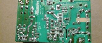
Impulse power block
Such surges and network outages are especially painful for power diodes, powerful transistors, PWM controllers, and capacitors. It’s good when your voltage converter is made without filling with compound. You can do the repair of such switching power supplies yourself.
Increasingly, voltage sources filled with compound are appearing. They are not accepted for repair even in specialized workshops. For them, the only repair option is replacement with a new one. Improper operation of these sources or connection of more powerful loads can also cause their failure.
There is no need to immediately send these converters for repair; the reasons for their failure can be quite simple, and you can easily deal with them. For more complex faults, some knowledge of electronics is required. Experience in repair comes with time, the more you do it, the more knowledge you will gain.
Repair of switching power supply
Most modern household electronic equipment has in its design independent or located on a separate board electronic modules that reduce and rectify the mains voltage.
There are several reasons here, but the main ones are:
- mains voltage fluctuations for which these buck-rectifier devices are not designed;
- non-compliance with operating rules;
- connecting a load for which the devices are not designed.
Of course, it can be very frustrating when you need to do urgent work, but the computer’s power module is faulty or the device breaks down while watching your favorite TV show.
Do not immediately panic and contact a repair shop or rush to the electronics supermarket to purchase a new unit. Often the causes of inoperability are so trivial that they can be eliminated at home, with minimal expenditure of money and nerves.
TV repair
A malfunction of the television power module is primarily indicated by the absence of light on the “sleep” mode diode. The first repair operations are:
checking for integrity (absence of break) of the power supply cord; disassembling the television receiver and releasing the electronic board; inspection of the power supply board for the presence of externally faulty parts (swollen capacitors, burnt spots on the printed circuit board, burst cases, charred surfaces of resistors); checking soldering points, with special attention paid to soldering the contacts of the pulse transformer.
If it was not possible to visually identify the defective part, then it is necessary to sequentially check the functionality of the fuse, diodes, electrolytic capacitors and transistors. Unfortunately, if the control microcircuits fail, their malfunction can only be determined in an indirect way - when the power supply does not become operational even with fully operational discrete elements.
In repair practice, there are cases when the power module does not work (does not start) and the fuse is not blown. This may indicate a breakdown (burnout) of the high-frequency pulse generator transistor.
The most common reasons for television units not working are:
- breakage of ballast resistances;
- inoperability (short circuit) of the high-voltage filter capacitor;
- malfunction of secondary voltage filter capacitors;
- breakdown or burnout of rectifier diodes.
All these parts (except for the rectifier diodes) can be checked without removing them from the board. If it is possible to determine the faulty part, then it is replaced and they begin to check the repairs performed. To do this, install an incandescent lamp in place of the fuse and connect the device to the network.
There are several possible behavior options for the repaired device:
- The light flashes and dims, the sleep mode LED lights up, and a raster appears on the screen. In this situation, the horizontal voltage is measured first. If its value is too high, it is necessary to check and replace the electrolytic capacitors with guaranteed serviceability. A similar situation occurs when optocoupler pairs malfunction.
- If the light flashes and goes out, the LED does not light up, the raster is missing, which means the pulse generator does not start. In this case, the voltage level on the electrolytic capacitor of the high-voltage filter is checked. If it is below 280.0...300.0 volts, then the following malfunctions are most likely:
- one of the rectifier bridge diodes is broken;
There is a large leakage of the capacitor (the capacitor is “aged”).
- If the light glows strongly, you must immediately disconnect the power module from the network and recheck all electronic parts.
If there is no voltage, it is necessary to recheck the integrity of the power circuits and all diodes of the high voltage rectifier.
The above sequence and test diagram allow you to identify the main malfunctions of the power supply of the television receiver.
Power supply device, step-down mains voltage converter
Here is a selection of materials:
The practice of electronic circuit design. The art of device development. Element base. Typical schemes. Examples of finished devices. Detailed descriptions. Online payment. Opportunity to ask questions to the authors
This power supply consists of high-voltage and low-voltage parts.
In the high-voltage part, the mains voltage is rectified and charges the filter capacitor. This results in a constant voltage of about 310 volts. Next, this voltage is converted into pseudo-rectangular oscillations with a frequency of 10 - 100 kHz, which allows, using small-sized pulse transformers, to be converted into low-voltage voltage with minimal losses.
In the low-voltage part, the incoming voltage with a frequency of 10 - 100 kHz is rectified, filtered and supplied to the load. In addition, there are control and feedback circuits that ensure the formation of the necessary signals and maintain the stability of the output voltage.
When looking at the power supply board, it is usually visually easy to understand where the high-voltage part is and where the low-voltage part is, since standards require that these parts be separated from each other by some distance in order to ensure user safety. The high-voltage part is where the mains wire goes. The low voltage part is where the load wires come from.
Most household devices contain switching power supplies built on the basis of two circuit solutions - half-bridge and single-cycle forward. See the diagram.
High voltage constant voltage source
To create a high voltage (30...35 kV at a load current of up to 1 mA) to power an electroeffluvial chandelier (A.L. Chizhevsky’s chandelier), a DC power source is designed based on a specialized microcircuit of the K1182GGZ . The power supply consists of a mains voltage rectifier on a diode bridge VD1, a filter capacitor C1 and a high-voltage half-bridge oscillator on a DA1 chip of the K1182GGZ type. The DA1 chip, together with transformer T1, converts direct rectified mains voltage into high-frequency (30...50 kHz) pulsed voltage. The rectified mains voltage is supplied to the DA1 microcircuit, and the starting circuit R2, C2 starts the microcircuit's self-oscillator. Chains R3, C3 and R4, C4 set the frequency of the generator. Resistors R3 and R4 stabilize the duration of the half-cycles of the generated pulses. The output voltage is increased by winding L4 of the transformer and supplied to a voltage multiplier using diodes VD2 - VD7 and capacitors C7 - C12. The rectified voltage is supplied to the load through limiting resistor R5. Line filter capacitor C1 is designed for an operating voltage of 450 V (K50-29), C2 - of any type for a voltage of 30 V. Capacitors C5, C6 are selected within the range of 0.022...0.22 μF for a voltage of at least 250 V (K71-7, K73 -17). Multiplier capacitors C7 - C12 type KVI-3 for voltage 10 kV. It is possible to replace it with capacitors of types K15-4, K73-4, POV and others with an operating voltage of 10 kV or higher.
Rice. 4. Circuit diagram of a high voltage DC power supply.
High-voltage diodes VD2 - VD7 type KTs106G (KTs105D). Limiting resistor R5 type KEV-1. It can be replaced with three MLT-2 type resistors of 10 MOhm each.
A television line transformer, for example, TVS-110LA, is used as a transformer. The high-voltage winding is left, the rest are removed and new windings are placed in their place. Windings L1, L3 each contain 7 turns of 0.2 mm PEL wire, and winding L2 contains 90 turns of the same wire. It is recommended to include a chain of resistors R5, which limits the short circuit current, in the “negative” wire, which is connected to the chandelier. This wire must have high-voltage insulation.
Major failures of switching power supplies
To eliminate any malfunction, you need to get to the pulse unit board. Also, after disassembling the case, you will need to clean all dust and dirt with a vacuum cleaner in order to better see the elements of the device. First of all, the switching power supply must be visually examined.
Here it is important to pay attention to whether there are any swollen capacitors on the board or burnt resistors. First of all, the fuse of the switching power supply is analyzed for serviceability. If it was not possible to visually check its integrity, then you should use a multimeter in continuity mode
If it was not possible to visually check its integrity, then you should use a multimeter in continuity mode.
Swollen capacitors in the power supply, as well as broken diodes, must be replaced with similar ones by desoldering. But the throttle, which often fails, can be repaired with your own hands.
To do this, you need to unsolder the inductor from the board of the switching power supply, and then replace the burnt wiring on it, having previously calculated the number of turns and their position. Thermistors in the switching power supply cannot be repaired. They just need to be replaced with suitable ones.
Even the slightest repair of a switching power supply is accompanied by cleaning the board and visual inspection. When identifying places with broken contacts, a soldering iron is used. The contacts are re-soldered with tin solder and tinning. Fan maintenance deserves special attention if it is installed in a switching power supply housing.
Repair of switching power supplies
Malfunctions of switching power supplies, repair
Based on the circuit diagram of the switching power supply, we will move on to its repair. Possible malfunctions:
- If the varistor and the fuse at the input or VCR1 have burned out, then we look further. Because they just don't burn.
- The diode bridge burned out. Usually this is a microcircuit. If there is a protective diode, then it usually lights up. They need to be replaced.
- The 400V capacitor C1 is damaged. Rarely, but it happens. Often its malfunction can be identified by appearance, but not always.
- If the switching transistor burns out, then unsolder it and check it. If faulty, replacement is required.
- If the PWM regulator burns out, then replace it.
- Short circuit or break in the transformer windings. The chances of repair are minimal.
- An optocoupler malfunction is an extremely rare case.
- Malfunction of the TL431 stabilizer. For diagnostics, we measure the resistance.
- If there is a short circuit in the capacitors at the output of the power supply, then we unsolder it and diagnose it with a tester.
Examples of repair of switching power supplies
For example, consider the repair of a switching power supply for several voltages.
The malfunction was the absence of output voltage at the output of the block.
For example, in one power supply two capacitors 1 and 2 in the primary circuit were faulty. But they weren't swollen.
On the second one the PWM controller did not work.
All the capacitors in the picture appear to be working, but the internal resistance turned out to be high. Moreover, the internal ESR resistance of capacitor 2 in the circle was several times higher than the nominal one. This capacitor is in the PWM regulator circuit, so the regulator did not work. After replacing this capacitor, the PWM started working and the functionality of the power supply was restored.
Read also: Flexible drive for engraver