Diagnosis of the power supply before repair
It is best to carry out visual diagnostics using a magnifying glass:
A burnt resistor with position number R18 was found on the board, and when tested, it was revealed that it was broken and the contact was broken:
The resistor could burn out if its rated power dissipation was exceeded for a long time. The burnt resistor was soldered out, and its seat was cleaned:
To replace a resistor you need to find out its value. To do this, a known-good power supply was disassembled. The indicated resistor turned out to have a resistance of 1 ohm:
Further along the circuit of this resistor, a broken capacitor with position number C6 was discovered, the continuity of which showed its low resistance, and therefore unsuitability for further use:
It was precisely the breakdown of this capacitor that could cause the resistor to burn out and further inoperability of the entire device as a whole. This capacitor has also been removed from its place, you can compare how small it is:
The broken capacitor is comparable to the head of a match; such a small part caused the breakdown of the power supply. Next to it on the board, parallel to it, there is a second similar capacitor, which has survived. Unfortunately, there was no replacement capacitor and all hopes rested on the remaining second capacitor. But in place of the burnt resistor, a resistor with the required resistance of 1 Ohm was selected, but not surface mounted:
This resistor was installed on the seat of the burnt one, the soldering areas were cleaned of flux residues, and the seat of the broken capacitor was varnished for better insulation and to eliminate the possibility of air breakdown of this place:
After a test run, the power supply started working in normal mode and the indicator LED stopped blinking:
Subsequently, the installed resistor was replaced with a surface-mount resistor and a second layer of varnish was applied in place of the removed capacitor:
Of course, it would be ideal to install a second capacitor, but even without it, the power supply works fine, without extraneous noise and flickering of the LED:
After connecting the adapter to the network, the output voltage was measured, it turned out to be within the normal range, namely 11.9 Volts:
At this point, the repair of the device can be considered complete, since its functionality has been restored and it can continue to be used for its intended purpose. It is worth noting that the block is made according to a very good design, which, unfortunately, it was not possible to sketch.
At the moment, a quick external inspection reveals a good mains and output filter, a well-thought-out circuitry for controlling the power transistor and good stabilization of the output voltage. The physical design of the device is also at a high level, the installation is rigid and smooth, the soldering is clean, and precision radio elements are used. All this allows you to obtain a high-quality device with precisely specified parameters and characteristics.
Among the general recommendations for troubleshooting, first of all you should carry out a visual inspection, paying attention to darkened areas of the board or damaged radio elements. If you detect a burnt resistor or fuse, you must ring the nearest parts directly connected to the visually damaged one.
Semiconductors and capacitors in high-voltage circuits are especially dangerous, which in the event of a breakdown can lead to irreversible consequences for the entire device if it is turned on repeatedly without identifying a complete list of damaged components. With correct and careful diagnostics, in most cases everything ends well and the breakdown can be eliminated by replacing the damaged parts with the same serviceable ones or those that are similar in nominal value and parameters.
Video instructions for repairing a switching power supply:
Switching power supplies are the most unreliable component in modern radio devices. This is understandable - huge currents, high voltages. All power consumed by the device passes through the UPS. At the same time, let’s not forget that the amount of power supplied by the UPS to the load can change tens of times, which cannot have a beneficial effect on its operation.
Most manufacturers use simple switching power supply circuits, and this is understandable. The presence of several levels of protection often only complicates repairs and has virtually no effect on reliability, since the increase in reliability due to an additional protection loop is compensated by the unreliability of additional elements, and during repairs it takes a long time to figure out what these parts are and why they are needed.
Of course, each switching power supply has its own characteristics, differing in the power supplied to the load, the stability of the output voltages, the range of operating mains voltages and other parameters that play a role during repairs only when you need to choose a replacement for a missing part.
It is clear that when making repairs it is advisable to have a diagram. Well, if it’s not there, simple TVs can be repaired without it. The operating principle of all switching power supplies is almost the same, the only difference is in the circuit designs and types of parts used.
- How to fix smartphone screen burn-in?
We will consider a technique developed by many years of repair experience. More precisely, this is not a technique, but a set of mandatory actions for repairs, proven by practice. For repairs, you need a tester (avometer) and, preferably, but not necessarily, an oscilloscope.
So, step-by-step instructions for repairing a switching power supply:
- We turn on the TV, make sure that it is not working, that the standby indicator is not on. If it lights up, then the problem is most likely not in the power supply. Just in case, you will need to check the horizontal scan supply voltage.
- Turn off the TV and disassemble it.
- We carry out an external inspection of the TV board, especially the area where the power supply is located. Sometimes swollen capacitors, burnt resistors, and more can be found. We'll have to check them out in the future.
- We carefully look at the soldering, especially the transformer, key transistor/microcircuit, and chokes.
- We check the power circuit: we call the power cord, fuse, power switch (if there is one), chokes in the power circuit, rectifier bridge. Often, with a faulty UPS, the fuse does not blow - it simply does not have time. If the key transistor breaks through, the ballast resistance is more likely to burn out than the fuse. It happens that the fuse burns due to a malfunction of the posistor, which controls the demagnetizing device (demagnetization loop). Be sure to check for a short circuit the terminals of the mains power filter capacitor without desoldering it, since in this way you can often check for breakdown the collector-emitter terminals of a key transistor or microcircuit if a power switch is built into it. Sometimes power is supplied to the circuit from the filter capacitor through ballast resistors, and if they break, it is necessary to check for breakdown directly at the switch electrodes.
- We check the remaining parts of the block - diodes, transistors, some resistors. First, we check without desoldering the part; desoldering it only when there is a suspicion that the part may be faulty. In most cases, such a check is sufficient. Ballast resistors often break. Ballast resistances have a small value (tenths of an Ohm, units of Ohm) and are designed to limit pulse currents, as well as for protection as fuses.
- We look to see if there are short circuits in the secondary power circuits - to do this, we check the capacitor terminals of the corresponding filters at the outputs of the rectifiers for a short circuit.
After completing all the checks and replacing faulty parts, you can begin testing under current. To do this, instead of the mains fuse, we connect a 150–200 Watt 220 Volt light bulb. This is necessary so that the light bulb protects the power supply in case the malfunction is not resolved. Disconnect the degaussing device.
Turn it on. At this stage there are three options:
- The light flashed brightly, then went out, and a raster appeared. Or the standby mode indicator lights up. In both cases, you need to measure the voltage supplying the horizontal scan - it varies for different TVs, but not more than 125 Volts. Often its value is written on the printed circuit board, sometimes near the rectifier, sometimes near the TDKS. If it is raised to 150–160 Volts, and the TV is in standby mode, then switch it to operating mode. Some TVs allow overvoltage at idle (when horizontal scanning does not work). If the voltage is too high in operating mode, check the electrolytic capacitors in the power supply only by replacing them with a known good one. The fact is that often electrolytic capacitors in a UPS lose their frequency properties and cease to perform their functions at the generation frequency, despite the fact that when tested by a tester using the charge-discharge method, the capacitor seems to be in good order. The optocoupler (if present) or the optocoupler control circuit may also be faulty. Check whether the output voltage is regulated by internal regulation (if any). If it is not adjustable, then you need to continue searching for faulty parts.
- The light flashed brightly and went out. Neither the raster nor the standby mode indication appeared. This indicates that the switching power supply does not start. It is necessary to measure the voltage on the surge protector capacitor; it should be 280–300 Volts. If it is not there, sometimes they put a ballast resistor between the mains rectifier bridge and the capacitor. Check the power supply and rectifier circuits again. If the voltage is too low, one of the diodes of the mains rectifier bridge may be broken or, more often, the mains power filter capacitor has lost capacity. If the voltage is normal, then you need to once again check the rectifiers of the secondary power supplies, as well as the starting circuit. The triggering circuit for simple TVs consists of several resistors connected in series. When testing a circuit, you need to measure the voltage drop across each of them, measuring the voltage directly at the terminals of each resistor.
- The light is on at full brightness. Turn off the TV immediately. Recheck all items. And remember - there are no miracles in radio engineering, it means you missed something somewhere, you didn’t check everything.
95% of the malfunctions fit into this diagram, but there are more complex malfunctions when you have to rack your brains. For such cases, you cannot write methods and you cannot create instructions.
- Do not throw away damaged devices, restore them. Of course, sometimes it’s cheaper and easier to buy new, but repairing is a rewarding and fun activity that allows you to develop skills in restoring and designing your own devices.
Typical faults in power supplies
The most popular are swollen capacitors. This usually happens due to overheating of the case or board. Next, oddly enough, is a broken power cord. Yes, yes, exactly the cord. Try changing it first. The third place is occupied by semiconductors. Usually these are transistors or diodes; they cannot withstand sudden overloads, and thermal breakdown occurs.
For repairs, you will need a multimeter, a soldering iron, a light bulb and a screwdriver. The light bulb is needed as a fuse; it can be connected between the power cable and the board if you are not sure of the result of the repair
Malfunctions that render a switching power supply inoperative can occur for a variety of reasons. Most often breakdowns occur due to:
- presence of mains voltage fluctuations. A malfunction can be caused by vibrations for which these buck-rectifier modules are not designed;
- connecting to the power supply loads that household appliances are not designed for;
- lack of protection. By not installing protection, some manufacturers simply save money. If such a problem is detected, you just need to install the protection in a specific place where it should be;
- failure to comply with operating rules and recommendations specified by manufacturers for specific models.
Moreover, recently a frequent cause of breakdown of voltage converters is factory defects or the use of low-quality parts during assembly.
Therefore, if you want your purchased switching power supply to work as long as possible, you should not buy it in dubious places and not from trusted people. Otherwise, it might just be wasted money.
After diagnosing the unit, the following faults are often discovered:
- 40% of cases – malfunction of the high-voltage part. This is evidenced by the burnout of the diode bridge, as well as the breakdown of the filter capacitor;
- 30% - breakdown of a bipolar (forming high-frequency pulses and located in the high-voltage part of the device) or power field-effect transistor;
- 15% - breakdown of the diode bridge in its low-voltage part;
Diode bridge
- Burnout (breakdown) of the inductor windings on the output filter is rare.
All other breakdowns can only be determined using special equipment, which is unlikely to be kept at home by the average person. For a deeper and more accurate check, a digital voltmeter and an oscilloscope are required. Therefore, if the breakdown does not lie in the four options above, then you will not be able to repair a power supply of this type at home.
As you can see, repairs carried out in this situation with your own hands can take a wide variety of forms. Therefore, if your computer or TV has stopped working due to a broken power supply, then you do not need to run to a repair service, but you can try to solve the problem on your own. At the same time, home repairs will cost significantly less. But if you cannot cope with the task on your own, then you can already go to the specialists from the repair service
What diagnostic methods for computer power supplies still exist?
Checking the power supply with a multimeter and a paper clip is enough to identify its malfunction in about 70-80% of cases. If you do not plan to repair it in the future, then you can limit yourself to this. In professional diagnostics of power supplies, not only these, but also other methods are used to localize the defect. Including:
- Checking the output voltage ripple using an oscilloscope. This is a rather expensive device, so it is unlikely that anyone will decide to buy it for a one-time job.
- Disassembly, inspection, checking voltages and resistances of printed circuit board elements for compliance with standards. It is dangerous to do this without special training, since power supplies accumulate household voltage in some parts. Accidentally touching any live part may result in electric shock.
- Current measurement. This is done using an ammeter built into the tester, which is connected to the break in the line being tested. To create a gap, board elements are usually desoldered.
- Testing on stands with specially selected equipment in various operating modes.
In short, there are quite a few methods for diagnosing power supplies, but not all of them are applicable or advisable at home. Except for research purposes, if, of course, the owner is interested in it.
Other articles on the site
- Is it worth buying a small (mini) computer?
- How much RAM do you need to work comfortably on your computer?
- Physical and virtual increase in computer RAM
- What is the normal processor temperature? How to measure it and, if necessary, reduce it?
Rules for disassembling a laptop power supply
To identify the cause, it is very important for the user to penetrate into the “heart” of the power supply, so initially it won’t hurt to thoroughly familiarize yourself with the recommendations of computer gurus on how to open a laptop power supply, especially since the opening process itself may differ for different laptop models.
If you examine the power supply carefully, you will find that it contains a narrow seam that encircles the device around its entire perimeter. It is on this seam that you should focus your attention, but before that, prepare tools that will allow you to disassemble the power supply without causing serious problems. For these purposes, in most cases you will need a scalpel, a soldering iron and a screwdriver.
Using a scalpel and a screwdriver, carefully cut the seam of the power supply
Holding a scalpel in your hands, you should carefully make cuts along the entire seam. Despite the fact that the internal elements of the power supply are accompanied by additional protection from mechanical damage, manifested in the form of a special metal casing, experienced users strongly recommend performing each action slowly.
The size of the seam differs for different laptop models, so the duration of such an opening can be completely different.
In the instructions on how to open a laptop power supply, you can find recommendations aimed at using physical force. In particular, experts advise using small hammers to tap on the scalpel. Indeed, the use of a hammer in some cases is justified, but it is only important to correctly calculate your own forces so that each blow with a hammer is aimed at destroying the seam, but at the same time it should not provoke damage to the metal casing inside.
Experienced specialists use special drill attachments to speed up the process of disassembling the power supply. Of course, this will significantly speed up the process, but at the same time the risk of damage to the device during opening increases significantly, so this method can only be used by those who have already become proficient and have sufficient experience in this area.
After the seam has been cut, a screwdriver is inserted into it, which is then used as a lever. By slightly prying with a screwdriver, you will be able to completely open the laptop's power supply.
It may happen that the user discovers a “groove-tooth” type connection, then it will be enough to pry off the places of such connections, after which the power supply housing will easily separate into two halves.
The power supply of a laptop and a computer differ even in appearance, so the process of assembly and disassembly is accompanied by some characteristic features. For this reason, the PC owner should delve into another algorithm, how to disassemble the computer power supply.
The computer power supply can be disassembled not only when a situation arises indicating its inoperability. This device can be subject to heavy dust, and dust, as you know, is the most important enemy for computer equipment. Timely cleaning of the power supply unit from dust contributes to the long-term operational performance of the PC.
Initially, you should unscrew all the screws with which the power supply is connected to the system unit. After this, the rectangular metal structure can be removed onto a flat surface. It is easy to find several screws on the power supply housing, which are also important to unscrew.
After performing these steps, the fan cover will be easily removed. Now nothing prevents you from cleaning the fan, which is a device in the cooling system.
Next, it is important to disconnect the board by unscrewing the four screws again. The board is easily detached and can be carefully cleaned using a soft brush.
When cleaning any components, experts recommend avoiding direct contact of the parts with human hands, since greasy places attract large amounts of dust more strongly. For this reason, the power supply will become dirty faster.
Assembling a computer power supply is not difficult, since all the actions performed initially are carried out again in exactly the same way, but only in the reverse order.
So, everyone who has become the owner of computer equipment can, if desired, not only successfully use all its functionality, but also, if necessary, independently “reanimate” their favorite computer. To do this, you just need to carefully study the recommendations of experienced gurus, who described step by step how to open the power supply of both a laptop and a computer.
Signs of a faulty power supply
The most obvious sign of a faulty voltage source is that the PC shows no signs of life when you try to turn it on. In this case, it is obvious that you must first check the computer's power supply. Other signs do not so clearly indicate PD:
- periodic freezes of the computer operating system;
- regular spontaneous PC reboots;
- the computer starts 2-3 times;
- Some peripheral devices do not work.
But even in these cases, it is advisable to diagnose the power supply first in order to localize the fault. Also, problems with power supply can be identified by the occurrence of extraneous noise - uncharacteristic squeaking, crackling, etc.
If, when you touch the PC case, you feel electric shocks, or even just tingling and mild discomfort, you should immediately turn off the computer, dismantle the power supply and begin diagnosing it, observing safety precautions.
Monoblock power supply repair
Power supply for Lenovo ThinkCentre m71z monoblock.
The monoblock did not turn on, there was no external damage, but the power supply did not turn on. After opening it, it turned out that the power supply did not have a standby voltage of +5V on the power supply.
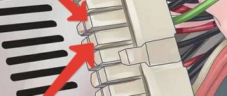
And immediately a burnt resistor is visually revealed, which is clearly missing 1 terminal. Black marks on the radiator. The photo was taken after it was dismantled.
Apparently, it served as a jumper from one part of the board to another. For further diagnostics, it was decided to connect the power supply to the network through a 40 W light bulb.
The light came on immediately. This means that there is a short circuit in the circuit and the resistor has failed. But how much current could damage it?
A protective diode goes directly to this element along the printed circuit board, which also turned out to be faulty because it was short-circuited. The path from the diode goes directly to the area of the powerful field-effect transistor.
To verify that the transistor is faulty, you need to unsolder it from the board (or simply remove the solder from the contacts with a braid), thereby eliminating the influence of the circuit on the measurements.
It turned out that the field worker was also faulty. It is necessary to select all parts similar to the faulty ones.
To replace the field-effect transistor, you need to unsolder this healthy inductor.
And finally, the 5B duty officers appear. Closed 5V to ground gave 12V. However. The monoblock refused to turn on. It's all because of the faulty north bridge. Colleagues at work changed it and the monoblock started up. Apparently, the power supply pulled the bridge along with it.
Causes and effects of nutrition-related problems
Complete failure and malfunction of the power supply most often occur due to:
- Voltage surges in the electrical network.
- Low quality of the PSU itself.
- Inconsistencies between power supply capabilities and load consumption (computer devices).
The consequences of a malfunction of the power supply, especially in combination with low quality manufacturing, can be not only breakdowns of the PC electronics, but also electric shock to the user.
Checking the input resistance
Repairing a Power Man 350 Watt power supply
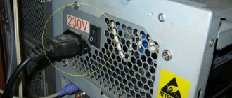
What do we do first? External and internal inspection. Let's look at the "offal". Are there any burnt radio elements? Maybe the board is charred somewhere, or a capacitor has exploded, or it smells like burnt silicon? We take all this into account during the inspection. Be sure to look at the fuse. If it burns out, then replace it with a temporary jumper for about the same amount of Amperes, and then measure the input resistance through two network wires. This can be done on the power supply plug with the “ON” button turned on. It should NOT be too small, otherwise, when you turn on the power supply, a short circuit will occur again.
If everything is OK, we turn on our power supply to the network using the network cable that comes with the power supply, and do not forget about the power button if you had it off.
Next, measure the voltage on the purple wire
In our case, the purple wire shows 0 Volts. We take a multimeter and connect the purple wire to ground. Ground is black wires with the inscription COM. COM – short for “common”, which means “general”. There are also some types of “lands”:
If you touch the ground and the purple wire, and the multimeter emits a meticulous “ppiiiiiiiiiiiiiiiiiiiiiiiiiiiiiiiiiiiiiiiiiiiiiight” signal and shows zeros on the display. Short circuit, definitely.
We are looking for a circuit diagram for this power supply. In our case, we used a Power Man 300 Watt circuit. They will still be similar. The only differences in the circuit are the serial numbers of the radio components on the board. If you know how to analyze a printed circuit board for compliance with the circuit, then this will not be a big problem.
And here is the circuit for Power Man 300W. Click on it to enlarge to full size.
As we see in the diagram, standby power, hereinafter referred to as standby power, is designated as +5VSB:
Directly from it goes a zener diode with a nominal value of 6.3 Volts to the ground. And as you remember, a zener diode is the same diode, but it is connected in reverse in circuits. The zener diode uses the reverse branch of the current-voltage characteristic. If the zener diode were live, then our +5VSB wire would not short to ground. Most likely the zener diode has burned out and the PN junction is destroyed.
What happens when various radio components burn from a physical point of view? Firstly, their resistance changes. For resistors, it becomes infinite, or in other words, goes into a break. With capacitors it sometimes becomes very small, or in other words, goes into a short circuit. With semiconductors, both of these options are possible, both a short circuit and an open circuit.
In our case, we can check this in only one way, by unsoldering one or both legs of the zener diode, as the most likely culprit of the short circuit. Next, we will check whether the short circuit between the duty switch and ground has disappeared or not. Why is this happening?
Let's remember some simple tips:
1) When connected in series, the rule of greater than greater works, in other words, the total resistance of the circuit is greater than the resistance of the larger resistor.
2) With a parallel connection, the opposite rule works, less than the smaller, in other words, the final resistance will be less than the resistance of the resistor of the smaller value.
You can take arbitrary resistor resistance values, calculate them yourself and see for yourself. Let's try to think logically, if one of the resistances of parallel-connected radio components is zero, what readings will we see on the multimeter screen? That's right, also equal to zero...
And until we eliminate this short circuit by desoldering one of the legs of the part that we consider to be problematic, we will not be able to determine in which part we have a short circuit. The point is that during audio testing, ALL parts connected in parallel to the part that is in a short circuit will ring short with the common wire!
We try to remove the zener diode. As soon as we touched it, it fell apart in two.
We check whether the short circuit in the duty and ground circuits has been eliminated or not. Indeed, the short circuit has disappeared. We bought a new zener diode and soldered it. When I turned on the power supply, it began to smoke.
Here I must remember one of the main rules of a repairman:
If something burns out, first find the reason for it, and only then replace the part with a new one or risk getting another burnt out part.
When we turned on the power supply again, we saw that the duty was too high: 8.5 Volts. We downloaded the datasheet on the chip, we see the maximum supply voltage for the PWM controller, equal to 16 Volts.
The problem of over-inflated duty voltage turns out to be a banal increase in the ESR of electrolytic capacitors in the duty circuits. We look for these capacitors in the diagram and check them.
It's time to check what he is capable of.
We check the first capacitor in the duty circuit.
ESR is within normal limits.
Finding the culprit of the problem
Checking the second one
We are waiting for some value to appear on the multimeter screen, but nothing has changed.
The culprit, or at least one of the culprits, has been found. We resolder the capacitor to exactly the same one, in terms of nominal value and operating voltage, taken from the donor power supply board. Here we want to go into more detail:
If you decide to put an electrolytic capacitor into an ATX power supply not from a donor, but a new one from a store, be sure to buy LOW ESR capacitors and not regular ones. Conventional capacitors do not work well in high-frequency circuits, but in the power supply, these are precisely the circuits.
So, turn on the power supply and measure the voltage at the control room again. We measure the voltage at the control room, relative to the ground. The voltage is 12 volts and a high-frequency whistle is heard.
The 10 µF capacitor needs to be replaced.
We measure ESR on the capacitor....
The result is the same as in the first case: the device goes off scale.
So, after going through the boards, I found the second capacitor I needed on one of the donor boards. Just in case, its ESR was measured. It turned out to be normal. After soldering the second capacitor into the board, I turn on the power supply using the key switch and measure the standby voltage. What was required, 5.02 volts... I measure all other voltages at the power supply connector. Everything corresponds to the norm. Operating voltage deviations are less than 5%. It remains to solder a 6.3 Volt zener diode.
The most common breakdowns
The most common problems with the power supply are:
- failure of 220 volt rectifier diodes;
- faulty key transistors;
- failure of the PWM chip.
In most cases, these problems cannot be detected by a simple visual inspection. You will need at least a multimeter. In general, any electronic component can fail, and it can cause a short circuit and overload other elements. Therefore, replacing a burnt component detected visually may not yield anything - it will only be a consequence. The original cause may be elsewhere.
Also, a malfunction can be caused by an overload of the source associated with the installation of additional equipment when upgrading a PC.
Visual inspection and simple repair of typical faults
After disassembling the power supply, you can conduct a visual inspection and identify faulty elements. If the inspection reveals no damage, testing is carried out using a multimeter. To check live batteries, the power supply must be connected to the network.
Identified faulty elements are soldered off, and new ones are soldered in instead. A common malfunction is the breaking of the wire that goes from the power supply to the laptop. Moreover, this often happens both at the base or near the plug, and in the middle, especially if during operation the wire lies on the floor and is periodically stepped on or run over with a chair. Therefore, ring the wire to check its integrity, do the same with the 220V wire that goes from the outlet to the power supply. We will not consider in detail the circuit design and repair of the power supply within this article, so I suggest watching a couple of videos on this topic.
After replacing the faulty elements, the power supply is connected to the laptop and tested on a working device under high loads on the processor, memory and video core.
Once the repair is complete, the power supply is assembled and inserted inside the case. The body can be reassembled using an adhesive seam or secured with electrical tape to match the color of the body. Next time disassembly will be very simple.
The difference between a bad power supply and a good one
How do you know which power supply you have, good or not powerful enough? There are several criteria by which a high-quality power supply is determined:
- A good one protects against power surges in the general network. If a strong surge occurs, the power supply itself will burn out, but will leave the computer and components unharmed.
- A good power supply has a convenient wiring system, it is modern, and you have the ability to connect and disconnect some cables yourself.
- A high-quality model has a good cooling system, it does not overheat, and the power supply fan does not make much noise during operation.
Features of repair work and tools for them
For a standard type of device, the above stages of diagnostics and repair work will be identical. This is due to the fact that they all have a typical structure.
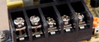
Soldering parts to the board
Also, in order to carry out high-quality independent repairs of a pulse voltage converter, you need a good soldering iron, as well as the ability to operate it. In this case, you will also need solder, alcohol, which can be replaced with purified gasoline, and flux. In addition to a soldering iron, the following tools will definitely be needed for repairs:
- Screwdriver Set;
- tweezers;
- household multimeter or voltmeter;
- incandescent lamp. Can be used as ballast load.
With such a set of tools, anyone can do simple repairs.
When planning to repair a damaged pulse voltage converter with your own hands, you need to understand that such manipulations are not carried out for products intended for complex replacement. They are not designed for repair and no technician will undertake to repair them, since it requires complete dismantling of the electronic filling and replacing it with a new working one.
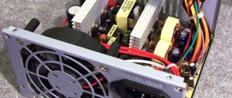
Switching power supply board
In all other cases, repairs at home and with your own hands are quite possible. Proper diagnosis is half the repair. Faults associated with the high-voltage part can be easily detected both visually and using a voltmeter. But a fuse malfunction can be detected if there is no voltage in the area after it.
If faults are detected with its help, all that remains is to simply replace them simultaneously. When carrying out repair work, it is necessary to rely on the appearance of the electronic board. Sometimes, in order to check each part, it is necessary to unsolder it and test it with a multimeter. It is advisable to check all details. Despite the difficulty of such a process, it will allow us to identify all damaged elements of the electrical circuit and replace them in time to prevent burnouts of the device in the foreseeable future.
Replacing burnt out parts
After all the burnt out parts have been replaced, you need to install a new fuse and check the repaired power supply by turning it on. Usually, if everything was done correctly, and all standards and instructions for repair work were followed, the converter will work.
Precautionary measures
For convenience, it is better to carry out the work of disassembling the power supply on a table. And to protect the table surface from damage, you should use oilcloth, a cutting board or a piece of plywood. To prevent the solvent from damaging the surface of the workplace, a low plastic tray in which the power supply is placed is useful. It is worth preparing a rag in advance to wipe off excess solvent or gasoline.
Important! Disconnect the power supply from the network and laptop! The power cord should be removed from the plug connector.
Sources
- https://tehnoobzor.com/schemes/repair/2857-bystryy-remont-impulsnyh-blokov-pitaniya-svoimi-rukami.html
- https://tyt-sxemi.ru/remont-bloka-pitaniya/
- https://nastroyvse.ru/devices/comp/kak-razobrat-blok-pitaniya.html
- https://www.RusElectronic.com/remont-kompyuternogo-bp-problemy-s-dezhurnym-napryazheniem/
- https://Acums.ru/akkumulyatory/dlya-kompyutera-i-noutbuka/kak-razobrat-blok-pitaniya-nb
- https://1posvetu.ru/ustrojstva/otremontirovat-impulsnyj-blok-pitaniya-svoimi-rukami.html
[collapse]