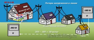
Using our calculator, you can calculate the cable cross-section by power (load) or current, taking into account the line length with a minimum error. The main indicators are the conductor material (copper, aluminum), voltage (220 V / 380 V) and load/current in the circuit. The method of laying the cable affects the cross-section of the conductor - closed cables require a larger cross-section, since due to limited heat transfer the metal heats up more. After carrying out the classic calculation for power/current, an additional calculation is carried out for the length of the conductor - the largest of the resulting pair of values is selected. The theoretical basis for the calculation is presented below in the form of formulas and tables. You may only be interested in the voltage loss calculator.
Related regulatory documents:
- PUE-7 “Rules for electrical installations”
- SP 76.13330.2016 “Electrical devices”
- GOST R 50571.5.52-2011/IEC 60364-5-52:2009 “Low-voltage electrical installations. Selection and installation of electrical equipment"
- GOST 31946-2012 “Self-supporting insulated and protected wires for overhead power lines”
- GOST 31947-2012 “Wires and cables for electrical installations for rated voltage up to 450/750 V”
- GOST 6323-79 “Wires with polyvinyl chloride insulation for electrical installations”
- GOST 31996-2012 “Power cables with plastic insulation for a rated voltage of 0.66; 1 and 3 kV"
- GOST 433-73 “Power cables with rubber insulation”
How to calculate cable cross-section by power?
First step . The total power of all electrical appliances that can be connected to the network is calculated:
Psum = (P1 + P2 + .. + Pn) × Kс
- P1, P2 .. – power of electrical appliances, W;
- Kc – demand coefficient (probability of simultaneous operation of all devices), default is 1.
Second step . Then the rated current in the circuit is determined:
I = Psum / (U × cos ϕ)
- Psum – total power of electrical appliances;
- U – network voltage;
- cos ϕ – power factor (characterizes power losses), default is 0.92.
Third step . At the last stage, tables are used in accordance with the PUE (Electrical Installation Rules).
Table of copper cable cross-section by current according to PUE-7
| Conductor cross-section, mm2 | Current, A, for wires laid | |||||
| open | in one pipe | |||||
| two single-core | three single-core | four single-core | one two-wire | one three-wire | ||
| 0.5 | 11 | — | — | — | — | — |
| 0.75 | 15 | — | — | — | — | — |
| 1 | 17 | 16 | 15 | 14 | 15 | 14 |
| 1.2 | 20 | 18 | 16 | 15 | 16 | 14.5 |
| 1.5 | 23 | 19 | 17 | 16 | 18 | 15 |
| 2 | 26 | 24 | 22 | 20 | 23 | 19 |
| 2.5 | 30 | 27 | 25 | 25 | 25 | 21 |
| 3 | 34 | 32 | 28 | 26 | 28 | 24 |
| 4 | 41 | 38 | 35 | 30 | 32 | 27 |
| 5 | 46 | 42 | 39 | 34 | 37 | 31 |
| 6 | 50 | 46 | 42 | 40 | 40 | 34 |
| 8 | 62 | 54 | 51 | 46 | 48 | 43 |
| 10 | 80 | 70 | 60 | 50 | 55 | 50 |
| 16 | 100 | 85 | 80 | 75 | 80 | 70 |
| 25 | 140 | 115 | 100 | 90 | 100 | 85 |
| 35 | 170 | 135 | 125 | 115 | 125 | 100 |
| 50 | 215 | 185 | 170 | 150 | 160 | 135 |
| 70 | 270 | 225 | 210 | 185 | 195 | 175 |
| 95 | 330 | 275 | 255 | 225 | 245 | 215 |
| 120 | 385 | 315 | 290 | 260 | 295 | 250 |
| 150 | 440 | 360 | 330 | — | — | — |
| 185 | 510 | — | — | — | — | — |
| 240 | 605 | — | — | — | — | — |
| 300 | 695 | — | — | — | — | — |
| 400 | 830 | — | — | — | — | — |
Table of cross-section of aluminum cable by current according to PUE-7
| Conductor cross-section, mm2 | Current, A, for wires laid | |||||
| open | in one pipe | |||||
| two single-core | three single-core | four single-core | one-two-core | one three-wire | ||
| 2 | 21 | 19 | 18 | 15 | 17 | 14 |
| 2.5 | 24 | 20 | 19 | 19 | 19 | 16 |
| 3 | 27 | 24 | 22 | 21 | 22 | 18 |
| 4 | 32 | 28 | 28 | 23 | 25 | 21 |
| 5 | 36 | 32 | 30 | 27 | 28 | 24 |
| 6 | 39 | 36 | 32 | 30 | 31 | 26 |
| 8 | 46 | 43 | 40 | 37 | 38 | 32 |
| 10 | 60 | 50 | 47 | 39 | 42 | 38 |
| 16 | 75 | 60 | 60 | 55 | 60 | 55 |
| 25 | 105 | 85 | 80 | 70 | 75 | 65 |
| 35 | 130 | 100 | 95 | 85 | 95 | 75 |
| 50 | 165 | 140 | 130 | 120 | 125 | 105 |
| 70 | 210 | 175 | 165 | 140 | 150 | 135 |
| 95 | 255 | 215 | 200 | 175 | 190 | 165 |
| 120 | 295 | 245 | 220 | 200 | 230 | 190 |
| 150 | 340 | 275 | 255 | — | — | — |
| 185 | 390 | — | — | — | — | — |
| 240 | 465 | — | — | — | — | — |
| 300 | 535 | — | — | — | — | — |
| 400 | 645 | — | — | — | — | — |
In the electrical installation rules of the 7th edition there are no tables of cable cross-section by power , there is only data on current strength. Therefore, when calculating sections using load tables on the Internet, you risk getting incorrect results.
Selection of wire (cable) cross-section by power - table
Example.
Let's take a one-room apartment. What electrical appliances do we use? Below you will see a table showing electrical appliances and tools used in everyday life:
Table 1.
| Household electrical appliance | Power, W | Household electrical appliance | Power, W |
| Bulb | 15 – 250 | Oven | 1000 – 3000 |
| Inkjet printer | 30 – 50 | microwave | 1500 – 3000 |
| Scales | 40 – 300 | Vacuum cleaner | 400 – 2000 |
| Audio system | 50 – 250 | Meat grinder | 1500 – 2200 |
| Computer | 300 – 800 | Toaster | 500 – 1500 |
| Laser printer | 200 – 500 | Grill | 1200 – 2000 |
| Copy machine | 300 – 1000 | Coffee grinder | 500 – 1500 |
| TV | 100 – 400 | Coffee maker | 500 – 1500 |
| Fridge | 150 – 2000 | Dishwasher | 1000 – 2000 |
| Washing machine | 1000 – 3000 | Iron | 1000 – 2000 |
| Electric kettle | 1000 –2000 | Heater | 500 – 3000 |
| Electric stove | 1000 – 6000 | Air conditioner | 1000 – 3000 |
Let's calculate the total power consumption of electrical appliances used in a one-room apartment. Let's take the minimum:
- Energy-saving lamps – 14 pieces, 15 W each;
- TV – 200 W;
- Audio system – 150 W;
- Computer – 500 W;
- Laser printer – 300 W;
- Refrigerator – 500 W;
- Washing machine – 2000 W;
- Electric kettle – 2000 W;
- Coffee maker – 1000 W;
- Microwave oven – 2000 W;
- Vacuum cleaner – 1200 W;
- Iron – 1000 W;
- Air conditioning – 2000 W.
Let's do the calculation:
14 × 15 = 210 W (energy saving lamps);
210 + 200 + 150 + 500 + 300 + 500 + 2000 + 1000 + 2000 + 1200 + 1000 + 2000 = 11,060 W = 11.06 kW
We have calculated the total load that the apartment can consume, but this will never happen. Why? Imagine that you turned on all electrical appliances at the same time. Could this happen to you? Of course not. Why would you turn on, for example, a TV, an audio system, a vacuum cleaner and an air conditioner at the same time in winter, or another combination of household appliances? Of course you won't do this.
Why am I writing all this, but to the fact that there is a so-called simultaneity coefficient, which is equal to ~ 0.75.
11.06 × 0.75 = 8.295 ~ 8.3 kW. You can connect this maximum load with the electrical appliances listed above for a short time. It is for information only.
But to calculate the cross-section of a wire (cable), you still need to take the total load without a coefficient. For this example, 11.06 ~ 11 kW.
We made this calculation for the input wire (cable), which will supply the entire apartment with a voltage of 220 V.
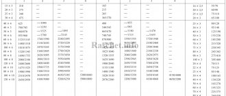
Table for selecting the cross-section of wire (cable) cores by power and current
Table 2.
How to use the table? We look at the table and select “Copper conductors of wires and cables” > “Voltage 220 V” > “Power, kW”, since we have a total power of 11 kW, we always select with a reserve and get 15.4, which corresponds to a cross-section of 10 mm². See below:
I advise you to always take the core cross-section (mm²) of the cable with a reserve, because the cable cores will not heat up under heavy load and in the future you may increase your arsenal of household electrical appliances and tools not only in quantity, but also in power.
Looking at this table, you can also determine the cross-section of a copper conductor for a voltage of 380 V, as well as an aluminum conductor for 220 and 380 V.
380 V (3 phases and zero) is used to connect cottages and where it is impossible to do without a three-phase system, for example, connecting 3-phase electric motors, air heaters, refrigeration units, etc.
Let's see what conductor cross-section is needed for each individual 220 V electrical appliance, knowing its power according to the passport:
Table 3.
| Cross-section of copper core, mm² | Electrical appliance power, W |
| 0,35 | 100 – 500 |
| 0,5 | 700 |
| 0,75 | 900 |
| 1,0 | 1200 |
| 1,2 | 1500 |
| 1,5 | 1800 – 2000 |
| 2,0 | 2500 |
| 2,5 | 3000 – 3500 |
| 3,0 | 4000 |
| 3,5 | 4500 – 5000 |
| 5,0 | 6000 |
Below is a table of the use of copper wires (cables) by cross-section:
Table 4.
| Section of copper conductors, mm² | Maximum permissible load, A (ampere) | Rated current of the circuit breaker, A | Maximum load U = 220 V, kW | Application example |
| 1,5 | 19 | 10 | 4,1 | Lighting |
| 2,5 | 27 | 16 | 5,9 | Sockets |
| 4 | 38 | 25 | 8,3 | Air conditioners, water heaters |
| 6 | 46 | 32 | 10,1 | Electric stoves, cabinets |
| 10 | 70 | 50 | 15,4 | Entering the apartment |
Selecting cable cross-section based on current strength
First step . The calculation is carried out in exactly the same way, that is, first the total power of all electrical appliances that can be connected to the network is calculated:
Psum = (P1 + P2 + .. + Pn) × Kс
- P1, P2 .. – power of electrical appliances, W;
- Kc – demand coefficient (probability of simultaneous operation of all devices), default is 1.
Second step . Then the rated current in the circuit is determined:
I = Psum / (U × cos ϕ)
- Psum – total power of electrical appliances;
- U – network voltage;
- cos ϕ – power factor (characterizes power losses), default is 0.92.
Third step . At the last stage, the same tables are used, according to the PUE (Electrical Installation Rules), which are located above.
Selecting wire cross-section for current
How to calculate the cross-section of a wire if only the current strength (I) is known? This calculation is made less frequently, but it is worth paying attention to this too.
Example.
It is necessary to find out what wire cross-section to use for an electric motor connected to a voltage (U) of 220 V. Its power (P) is not known.
Briefly connect the electric motor to a 220 V network and measure the current (I) using electric clamps. For example, the current is 10 A.
You can use a formula that can quickly calculate everything:
From this formula we find power (P):
P = IU
P = 10 × 220 = 2200 W = 2.2 kW
So, the power of the electric motor is 2.2 kW and the power consumption is 10 A. Using Table 2, we determine the cross-section of the wire, “Copper cores of wires and cables” > “Voltage 220 V” > “Current, A”. The first number starts with 19, and we have 10 A, opposite this number the wire cross-section is 1.5 mm². For our example, 1.5 mm² is more than enough.
In the same table we see that an aluminum wire (cable) with a cross-section of 2.5 mm² is also suitable.
Using simple calculations, we found out the current and wire cross-section, and at the same time the power of the electric motor for a voltage of 220 V. In the same way, you can find out the wire cross-section for other electricity consumers.
Heating of cable cores
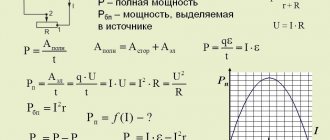
To determine the heating temperature of the cable cores when exposed to a current lasting up to 4 s, it is recommended to use the attached nomogram (Fig. 7.1).
The nomogram is based on equation (7.1), expressing the dependence of the temperature of the core immediately after on the temperature of the core before the short circuit, the short circuit mode, the design and thermophysical parameters of the core:
where He is the core temperature before the short circuit, °C, calculated using formula (7.3);
a is the reciprocal of the temperature coefficient of electrical resistance at 0°C, equal to 228°C;
where b is a constant characterizing the thermophysical characteristics of the core material, equal to 45.65 kA for aluminum;
Vter – thermal impulse from the short-circuit current, kA2·s – formula (2.45);
s – core cross-section, mm2.
On the nomogram, the core temperature values before (n) are plotted along the horizontal axis, and the temperature values after (?k) are plotted along the vertical axis for the values of the coefficient k, which characterizes the relationship between the thermal impulse, the core cross-section and the thermophysical characteristics of the core material.
The value of the initial core temperature up to is determined by the formula: n
where 0 is the actual ambient temperature during the short circuit, °C;
dd – the value of the calculated long-term permissible core temperature, °C, equal for cables with impregnated paper insulation for voltages of 1 kV - 80°C, 6 kV - 65°C and 10 kV - 60°C, for cables with plastic insulation
tion – 70°С and for cables with vulcanized polyethylene insulation – 90°С;
ambient – the value of the estimated ambient (air) temperature of 25°C;
Iwork – the value of the current before (motor operating current), A, is determined through the rated current of the electric motor Idn and the load factor kzgr using the formula:
where the rated current Idn is calculated by the formula:
Iadd – long-term permissible cable current, taking into account the correction for the number of adjacent cables and the ambient temperature, A, is determined by the formula:
where the long-term permissible currents Idd for cables of various sections are taken according to Tables 7.2, 7.3 [7].
For cables laid in the air inside and outside buildings, for any number of them, k' = 1. The value of k" can be determined by the formula:
where the temperatures dd, 0, amb have the same meaning as in the formula for calculating the initial heating temperature of the cable cores (7.3).
In the AR and ATS modes, the initial temperature values are assumed to be equal to the temperature value after the first exposure to the short-circuit current.
Table 7.2. Values of continuous permissible currents Idd for three-core cables with copper and aluminum conductors with impregnated paper insulation, laid in the air
Notes: 1. Loads for cables with aluminum conductors are indicated in the denominator.
2. Loads for three-core 1 kV cables are also valid for four-core cables with a neutral core of a smaller cross-section.
3. Loads for four-core cables with cores of equal cross-section are determined by multiplying the loads for three-core cables by a factor of 0.93.
Table 7.3. Values of continuous permissible currents Idd for cables for voltage 1 kV with rubber and plastic insulation, with copper and aluminum conductors, laid in the air
Notes: 1. Loads for cables with aluminum conductors are indicated in the denominator.
2. Loads for rubber-insulated cables are determined by multiplying the loads given in the table by a factor of 0.95.
3. Loads for cables with vulcanized polyethylene insulation are determined by multiplying the loads given in the table by a factor of 1.16.
4. Loads for four-core cables with cores of equal cross-section are determined by multiplying the loads for three-core cables by a factor of 0.882.