The power and current cable cross-section calculator will help you calculate the minimum cable cross-section required for safe operation of electrical wiring to avoid overheating, insulation melting, short circuits and fires.
The calculator allows you to calculate the cable cross-section by current or power, based on the parameters of the total load and incoming voltage. This takes into account the installation conditions, wire manufacturing materials, possible voltage losses and conductor selection criteria. The functionality of the section also allows you to calculate the maximum current and load on a conductor with specified parameters and select protection devices (circuit breakers, differential circuit breakers and RCDs).
How to calculate the cable cross-section:
- Indicate the source data (current or power), voltage, conductor material (copper or aluminum), type of wiring (open or closed in a pipe), number of wires (when laying communications in a pipe);
- Note additional conditions (wire length, permissible losses);
- Click on the “Calculate” button and save the resulting parameters.
The cable cross-section calculator works online and offline. Please note: it is for guidance only and cannot guarantee 100% accuracy of the calculations. However, the more valid data you enter into the appropriate fields, the higher the match rate will be.
Related regulatory documents:
- PUE-7 “Rules for electrical installations”
- SP 76.13330.2016 “Electrical devices”
- GOST R 50571.5.52-2011/IEC 60364-5-52:2009 “Low-voltage electrical installations. Selection and installation of electrical equipment"
- GOST 31946-2012 “Self-supporting insulated and protected wires for overhead power lines”
- GOST 31947-2012 “Wires and cables for electrical installations for rated voltage up to 450/750 V”
- GOST 6323-79 “Wires with polyvinyl chloride insulation for electrical installations”
- GOST 31996-2012 “Power cables with plastic insulation for a rated voltage of 0.66; 1 and 3 kV"
- GOST 433-73 “Power cables with rubber insulation”
How to calculate cable cross-section by power: formula
Before choosing a cable cross-section based on power, you need to calculate its total value and make a list of electrical appliances located in the territory to which the cable is laid. The power must be indicated on each device; the corresponding units of measurement will be written next to it: W or kW (1 kW = 1000 W). Then you will need to add up the power of all equipment and get the total.
1️⃣ First step. The total power of all electrical appliances that can be connected to the network is calculated:
Psum = (P1 + P2 + .. + Pn) × Kс
- P1, P2 .. – power of electrical appliances, W;
- Kc – demand coefficient (probability of simultaneous operation of all devices), default is 1.
2️⃣ Second step. Then the rated current in the circuit is determined:
I = Psum / (U × cos ϕ)
- Psum – total power of electrical appliances;
- U – network voltage;
- cos ϕ – power factor (characterizes power losses), default is 0.92.
3️⃣ Third step. At the last stage, tables are used in accordance with the PUE (Electrical Installation Rules).
Table of copper cable cross-section by current according to PUE-7
| Conductor cross-section, mm2 | Current, A, for wires laid | |||||
| open | in one pipe | |||||
| two single-core | three single-core | four single-core | one two-wire | one three-wire | ||
| 0.5 | 11 | – | – | – | – | – |
| 0.75 | 15 | – | – | – | – | – |
| 1 | 17 | 16 | 15 | 14 | 15 | 14 |
| 1.2 | 20 | 18 | 16 | 15 | 16 | 14.5 |
| 1.5 | 23 | 19 | 17 | 16 | 18 | 15 |
| 2 | 26 | 24 | 22 | 20 | 23 | 19 |
| 2.5 | 30 | 27 | 25 | 25 | 25 | 21 |
| 3 | 34 | 32 | 28 | 26 | 28 | 24 |
| 4 | 41 | 38 | 35 | 30 | 32 | 27 |
| 5 | 46 | 42 | 39 | 34 | 37 | 31 |
| 6 | 50 | 46 | 42 | 40 | 40 | 34 |
| 8 | 62 | 54 | 51 | 46 | 48 | 43 |
| 10 | 80 | 70 | 60 | 50 | 55 | 50 |
| 16 | 100 | 85 | 80 | 75 | 80 | 70 |
| 25 | 140 | 115 | 100 | 90 | 100 | 85 |
| 35 | 170 | 135 | 125 | 115 | 125 | 100 |
| 50 | 215 | 185 | 170 | 150 | 160 | 135 |
| 70 | 270 | 225 | 210 | 185 | 195 | 175 |
| 95 | 330 | 275 | 255 | 225 | 245 | 215 |
| 120 | 385 | 315 | 290 | 260 | 295 | 250 |
| 150 | 440 | 360 | 330 | – | – | – |
| 185 | 510 | – | – | – | – | – |
| 240 | 605 | – | – | – | – | – |
| 300 | 695 | – | – | – | – | – |
| 400 | 830 | – | – | – | – | – |
Table of cross-section of aluminum cable by current according to PUE-7
| Conductor cross-section, mm2 | Current, A, for wires laid | |||||
| open | in one pipe | |||||
| two single-core | three single-core | four single-core | one two-wire | one three-wire | ||
| 2 | 21 | 19 | 18 | 15 | 17 | 14 |
| 2.5 | 24 | 20 | 19 | 19 | 19 | 16 |
| 3 | 27 | 24 | 22 | 21 | 22 | 18 |
| 4 | 32 | 28 | 28 | 23 | 25 | 21 |
| 5 | 36 | 32 | 30 | 27 | 28 | 24 |
| 6 | 39 | 36 | 32 | 30 | 31 | 26 |
| 8 | 46 | 43 | 40 | 37 | 38 | 32 |
| 10 | 60 | 50 | 47 | 39 | 42 | 38 |
| 16 | 75 | 60 | 60 | 55 | 60 | 55 |
| 25 | 105 | 85 | 80 | 70 | 75 | 65 |
| 35 | 130 | 100 | 95 | 85 | 95 | 75 |
| 50 | 165 | 140 | 130 | 120 | 125 | 105 |
| 70 | 210 | 175 | 165 | 140 | 150 | 135 |
| 95 | 255 | 215 | 200 | 175 | 190 | 165 |
| 120 | 295 | 245 | 220 | 200 | 230 | 190 |
| 150 | 340 | 275 | 255 | – | – | – |
| 185 | 390 | – | – | – | – | – |
| 240 | 465 | – | – | – | – | – |
| 300 | 535 | – | – | – | – | – |
| 400 | 645 | – | – | – | – | – |
In the Electrical Installation Rules, 7th edition, there are no tables of cable cross-section by power, there is only data on current strength. Therefore, when calculating sections using load tables on the Internet, you risk getting incorrect results.
5 Single-wire and multi-wire conductors
The cores should not have burrs, cutting edges or bulging of individual wires.
5.1 Single-wire and multi-wire (for large cross-sections) conductors (class 1)
5.1.1 Design
a) For single-wire and multi-wire (for large cross-sections)
cores (class 1) use one of the materials listed in section 4.
b) Solid copper conductors must be round. For multi-core cables and wires, it is allowed to use shaped single-wire copper conductors with a cross-section of 25-50 mm .
Note - Solid copper conductors with a nominal cross-section of at least
70 mm
are intended for special types of cables, such as mineral insulated cables, but not for general purpose cables.
c) Single-wire conductors of aluminum and aluminum alloy with a nominal cross-section up to and including 35 mm must be round. Larger gauge conductors must be round for single-core cables and wires and may be round or shaped for multi-core cables and wires. For multi-core cables and wires, it is allowed to use shaped single-wire conductors made of aluminum and aluminum alloy with a cross-section of 25 and 35 mm .
5.1.2 Electrical resistance
The electrical resistance of the conductor at a temperature of 20 °C, determined in accordance with section 7, must be no more than the value specified in Table 3. Table 3 - Single-wire
and multi-wire (for large cross-sections)
class 1 conductors for single-core and multi-core cables
and wires
| Nominal cross-section, mm | Minimum number of core wires | Electrical resistance of 1 km of core at a temperature of 20 °C, Ohm, no more | |||
| Cu | A.I. | Round Annealed Copper Cores | Round or shaped conductors made of aluminum or aluminum alloy | ||
| without cover | with metal coating | ||||
| 0,03 | 1 | — | 588,0 | 617,3 | — |
| 0,05 | 1 | — | 347,9 | 365,3 | — |
| 0,08 | 1 | — | 225,3 | 238,8 | — |
| 0,12 | 1 | — | 130,8 | 138,6 | — |
| 0,20 | 1 | — | 88,8 | 90,4 | — |
| 0,35 | 1 | — | 50,7 | 51,8 | — |
| 0,50 | 1 | — | 36,0 | 36,7 | — |
| 0,75 | 1 | — | 24,5 | 24,8 | — |
| 1,0 | 1 | — | 18,1 | 18,2 | — |
| 1,5 | 1 | 1 | 12,1 | 12,2 | 18,1 |
| 2,5 | 1 | 1 | 7,41 | 7,56 | 12,1 |
| 4 | 1 | 1 | 4,61 | 4,70 | 7,41 |
| 6 | 1 | 1 | 3,08 | 3,11 | 5,11 |
| 10 | 1 | 1 | 1,83 | 1,84 | 3,08 |
| 16 | 1 | 1 | 1,15 | 1,16 | 1,91 |
| 25 | 1 | 1 | 0,727 | — | 1,20 |
| 35 | 1 | 1 | 0,524 | — | 0,868 |
| 50 | 1 | 1 | 0,387 | — | 0,641 |
| 70 | 1 | 1 | 0,268 | — | 0,443 |
| 95 | 1 | 1 | 0,193 | — | 0,320 |
| 120 | 1 | 1 | 0,153 | — | 0,253 |
| 150 | 1 | 1 | 0,124 | — | 0,206 |
| 185 | 1 or 35 | 1 | 0,101 | — | 0,164 |
| 240 | 1 or 35 | 1 | 0,0775 | — | 0,125 |
| 300 | 1 or 35 | 1 | 0,0620 | — | 0,100 |
| 400 | 1 or 35 | 1 or 35 | 0,0465 | — | 0,0778 |
| 500 | 35 | 1 or 35 | 0,0366 | — | 0,0605 |
| 625, 630 | 59 | 1 or 59 | 0,0283 | — | 0,0469 |
| 800 | 59 | 1 or 59 | 0,0221 | — | 0,0367 |
| 1000 | 59 | 1 or 59 | 0,0176 | — | 0,0291 |
| 1200 | — | 1 | — | — | 0,0247 |
| Aluminum conductors with a nominal cross-section up to 35 mm inclusive are round only; see item c) 5.1.1. See note to b) 5.1.1. See note to 5.1.2. For single-core cables, four sectored core pieces can be combined to form a round core. The maximum electrical resistance of the formed core must be equal to 25% of the value for each of the four sector parts of the core. | |||||
NOTE For solid aluminum alloy conductors having the same nominal cross-section as aluminum conductors, the electrical resistance value given in Table 3 shall be multiplied by a factor of 1.162 unless otherwise specified by agreement between the manufacturer and the purchaser.
5.2 Stranded round unsealed conductors (class 2)
5.2.1 Design
a) For stranded round unsealed conductors (class 2), use one of the materials listed in section 4.
b) The nominal cross-section of stranded aluminum or aluminum alloy power cables must be at least 10 mm.
c) All wires of each core must be of the same nominal diameter.
d) The number of wires of each core must be not less than the number of wires specified in Table 4. Table 4 - Class 2 stranded cores for single-core and multi-core cables and wires
| Nominal cross-section, mm | Minimum number of core wires | Electrical resistance of 1 km of core at a temperature of 20 °C, Ohm, no more | |||||||
| round | round compacted | shaped | Annealed copper core | Aluminum or aluminum alloy core | |||||
| Cu | A.I. | Cu | A.I. | Cu | A.I. | Uncoated wire | Metal Coated Wire | ||
| 0,5 | 7 | — | — | — | — | — | 36,0 | 36,7 | — |
| 0,75 | 7 | — | — | — | — | — | 24,5 | 24,8 | — |
| 1,0 | 7 | — | — | — | — | — | 18,1 | 18,2 | — |
| 1,5 | 7 | 7 | 6 | — | — | — | 12,1 | 12,2 | 22,7 |
| 2,5 | 7 | 7 | 6 | — | — | — | 7,41 | 7,56 | 12,4 |
| 4 | 7 | 7 | 6 | — | — | — | 4,61 | 4,70 | 7,41 |
| 6 | 7 | 7 | 6 | — | — | — | 3,08 | 3,11 | 5,11 |
| 10 | 7 | 7 | 6 | 6 | — | — | 1,83 | 1,84 | 3,08 |
| 16 | 7 | 7 | 6 | 6 | — | — | 1,15 | 1,16 | 1,91 |
| 25 | 7 | 7 | 6 | 6 | 6 | 6 | 0,727 | 0,734 | 1,20 |
| 35 | 7 | 7 | 6 | 6 | 6 | 6 | 0,524 | 0,529 | 0,868 |
| 50 | 19 | 19 | 6 | 6 | 6 | 6 | 0,387 | 0,391 | 0,641 |
| 70 | 19 | 19 | 12 | 12 | 12 | 12 | 0,268 | 0,270 | 0,443 |
| 95 | 19 | 19 | 15 | 15 | 15 | 15 | 0,193 | 0,195 | 0,320 |
| 120 | 37 | 37 | 18 | 15 | 18 | 15 | 0,153 | 0,154 | 0,253 |
| 150 | 37 | 37 | 18 | 15 | 18 | 15 | 0,124 | 0,126 | 0,206 |
| 185 | 37 | 37 | 30 | 30 | 30 | 30 | 0,0991 | 0,100 | 0,164 |
| 240 | 37 | 37 | 34 | 30 | 34 | 30 | 0,0754 | 0,0762 | 0,125 |
| 300 | 61 | 61 | 34 | 30 | 34 | 30 | 0,0601 | 0,0607 | 0,100 |
| 400 | 61 | 61 | 53 | 53 | 53 | 53 | 0,0470 | 0,0475 | 0,0778 |
| 500 | 61 | 61 | 53 | 53 | 53 | 53 | 0,0366 | 0,0369 | 0,0605 |
| 625 , 630 | 91 | 91 | 53 | 53 | 53 | 53 | 0,0283 | 0,0286 | 0,0469 |
| 800 | 91 | 91 | 53 | 53 | — | — | 0,0221 | 0,0224 | 0,0367 |
| 1000 | 91 | 91 | 53 | 53 | — | — | 0,0176 | 0,0177 | 0,0291 |
| 1200 | 0,0151 | 0,0151 | 0,0247 | ||||||
| 1400 | 0,0129 | 0,0129 | 0,0212 | ||||||
| 1600 | 0,0113 | 0,0113 | 0,0186 | ||||||
| 1800 | 0,0101 | 0,0101 | 0,0165 | ||||||
| 2000 | 0,0090 | 0,0090 | 0,0149 | ||||||
| 2500 | 0,0072 | 0,0072 | 0,0127 | ||||||
| These sections are not preferred. For special applications, other non-preferred conductor cross-sections are permitted but are not covered by this standard. The minimum number of wires for these sections is not standardized. The cores of these sections can be formed from four, five or six identical sectors. For stranded aluminum alloy conductors having the same nominal cross-section as aluminum conductors, the value of electrical resistance shall be agreed upon between the manufacturer and the purchaser unless specified in cable standards or specifications. | |||||||||
5.2.2 Electrical resistance
The electrical resistance of the core at a temperature of 20 °C, determined in accordance with section 7, must be no more than the value specified
in table 4
.
5.3 Stranded round cores and stranded shaped cores (class 2)
5.3.1 Design
a) For stranded round compacted conductors and stranded shaped conductors (class 2), use one of the materials given in section 4. The nominal cross-section of stranded round compacted conductors of aluminum or aluminum alloy shall be not less than 10 mm. The nominal cross-section of stranded shaped conductors made of copper, aluminum or aluminum alloy must be at least 25 mm.
b) The ratio between the diameters of two different wires of the same core should be no more than two.
c) The number of wires of each core must be at least the number of wires indicated in Table 4.
Note - This requirement applies to cores made from round wires before compaction and does not apply to cores twisted from pre-profiled wires.
d) In compacted conductors, wire breakage or skipping is allowed if the electrical resistance of the conductors meets the requirements of this standard.
5.3.2 Electrical resistance
The electrical resistance of the core at a temperature of 20 °C, determined in accordance with section 7, must not exceed the value specified
in table 4.
Selecting cable cross-section based on current strength: calculation formula
The amount of current passing through a conductor depends on the length, width, resistivity of the latter and on temperature. When heated, the electric current decreases.
1️⃣ First step. The calculation is carried out in exactly the same way, that is, first the total power of all electrical appliances that can be connected to the network is calculated:
Psum = (P1 + P2 + .. + Pn) × Kс
- P1, P2 .. – power of electrical appliances, W;
- Kc – demand coefficient (probability of simultaneous operation of all devices), default is 1.
2️⃣ Second step. Then the rated current in the circuit is determined:
I = Psum / (U × cos ϕ)
- Psum – total power of electrical appliances;
- U – network voltage;
- cos ϕ – power factor (characterizes power losses), default is 0.92.
3️⃣ Third step. At the last stage, the same tables are used, according to the PUE (Electrical Installation Rules), which are located above.
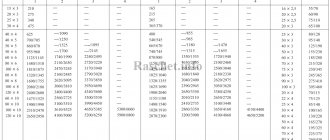
Active and inductive resistance of wires SIP-1, SIP-2, SIP-4
The values of active and inductive resistances for wires SIP-1, SIP-2 and SIP-4 are given in TU 16-705.500-2006 “Self-supporting insulated and protected wires for overhead power lines”, tables B.1, B.2.
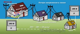
Calculation of cable cross-section by length: formula
The cable length affects the voltage loss. Thus, the voltage at the end of the conductor may decrease and be insufficient to operate the electrical appliance. For household electrical networks, these losses can be neglected. It will be enough to take a cable 10-15 cm longer. This reserve will be used for switching and connection. If the ends of the wire are connected to the shield, then the spare length should be even greater, since circuit breakers will be connected.
1️⃣ First step. First, the rated current in the circuit is determined:
I = Psum / (U × cos ϕ)
- Psum – total power of electrical appliances;
- U – network voltage;
- cos ϕ – power factor (characterizes power losses), default is 0.92.
2️⃣ Second step. Then the conductor resistance is calculated:
R = dU/I
- dU – voltage loss, no more than 5% (0.05);
- I – current strength.
3️⃣ Third step. The cross-section of the current-carrying conductor is calculated using the formula:
S = ρ × L/R
- ρ – metal resistivity, copper (0.0175), aluminum (0.028);
- L – conductor length;
- R – conductor resistance.
How to choose cable sections?
There are several more criteria that the cross-section of the wires used must meet:
- Length of cable
. The longer the wire, the greater the current loss observed in it. This again occurs as a result of an increase in resistance, which increases as the length of the conductor increases. This is especially noticeable when using aluminum wiring. When using copper wires to organize electrical wiring in an apartment, the length, as a rule, is not taken into account - the standard margin of 20–30% (for hidden wiring) is more than enough to compensate for possible increases in resistance associated with the length of the wire. - Type of wires used
. There are 2 types of conductors used in household electricity supply - copper or aluminum based. Copper wires are of better quality and have less resistance, but aluminum wires are cheaper. In full compliance with the standards, aluminum wiring copes with its tasks no worse than copper, so you need to carefully weigh your choice before purchasing a wire. - Electrical panel configuration
. If all the wires supplying consumers are connected to one circuit breaker, then it will be the weak point in the system. A heavy load will lead to heating of the terminal blocks, and non-compliance with the rating will lead to its constant operation. It is recommended to divide the electrical wiring into several “beams” with the installation of a separate machine.
In order to determine the exact data for choosing the cross-section of electrical wiring cables, it is necessary to take into account any, even the most insignificant parameters, such as:
- Type and type of insulation of electrical wiring;
- Length of sections;
- Laying methods and options;
- Features of temperature conditions;
- Humidity level and percentage;
- The maximum possible value of superheat;
- The difference in the powers of all current receivers belonging to the same group. All these and many other indicators can significantly increase the efficiency and benefits of energy use on any scale. In addition, correct calculations will help avoid cases of overheating or rapid abrasion of the insulating layer.
In order to correctly determine the optimal cable cross-section for any human household needs, it is necessary in all general cases to use the standardized following rules:
- for all sockets that will be installed in the apartment, it is necessary to use wires with an appropriate cross-section of 3.5 mm²;
- for all spotlighting elements, it is necessary to use electrical wiring cables with a cross-section of 1.5 mm²;
- As for high-power devices, cables with a cross-section of 4-6 mm² should be used.
If some doubts arise during the installation or calculation process, it is better not to act blindly. The ideal option would be to refer to the appropriate table of calculations and standards.
Table: Cable cross-section for closed and open wiring
Video: How to choose a wire cross-section?
Open and closed wiring
Depending on the placement, wiring is divided into 2 main types: closed and open.
Today, hidden wiring is installed in apartments. Special recesses are created in the walls and ceilings to accommodate cables. After installing the conductors, the recesses are plastered. Copper wires are used. Everything is planned in advance, because over time, to build up electrical wiring or replace elements, you will have to dismantle the finishing. For hidden finishing, wires and cables that have a flat shape are often used.
When laid open, the wires are installed along the surface of the room. Advantages are given to flexible conductors that have a round shape. They are easy to install in cable channels and pass through the corrugation. When calculating the load on the cable, the method of laying the wiring is taken into account.
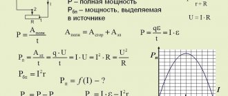
Wire resistance
Electrical resistance is the main characteristic of conductor materials. Depending on the area of application of the conductor, the value of its resistance can play both a positive and negative role in the functioning of the electrical system. Also, the specific application of the conductor may necessitate taking into account additional characteristics, the influence of which in a particular case cannot be neglected.
The nature of resistance
Conductors are pure metals and their alloys. In a metal, atoms fixed in a single “strong” structure have free electrons (the so-called “electron gas”). It is these particles that in this case are the charge carriers. Electrons are in constant, random motion from one atom to another. When an electric field appears (connecting a voltage source to the ends of the metal), the movement of electrons in the conductor becomes ordered. Moving electrons encounter obstacles on their path caused by the peculiarities of the molecular structure of the conductor. When they collide with a structure, charge carriers lose their energy, giving it to the conductor (heating it). The more obstacles a conductive structure creates to charge carriers, the higher the resistance.
As the cross section of the conducting structure increases for one number of electrons, the “transmission channel” will become wider and the resistance will decrease. Accordingly, as the length of the wire increases, there will be more such obstacles and the resistance will increase.
Thus, the basic formula for calculating resistance includes the length of the wire, the cross-sectional area and a certain coefficient that relates these dimensional characteristics to the electrical quantities of voltage and current (1). This coefficient is called resistivity. R= r*L/S (1)
Resistivity
Resistivity is constant and is a property of the substance from which the conductor is made. Units of measurement r - ohm*m. Often the resistivity value is given in ohm*mm sq./m. This is due to the fact that the cross-sectional area of the most commonly used cables is relatively small and is measured in mm2. Let's give a simple example.
Task No. 1. Copper wire length L = 20 m, cross-section S = 1.5 mm. sq. Calculate the wire resistance. Solution: resistivity of copper wire r = 0.018 ohm*mm. sq./m. Substituting the values into formula (1) we get R=0.24 ohms. When calculating the resistance of the power system, the resistance of one wire must be multiplied by the number of wires. If instead of copper you use aluminum with a higher resistivity (r = 0.028 ohm * mm sq. / m), then the resistance of the wires will increase accordingly. For the example above, the resistance will be R = 0.373 ohms (55% more). Copper and aluminum are the main materials for wires. There are metals with lower resistivity than copper, such as silver. However, its use is limited due to its obvious high cost. The table below shows the resistance and other basic characteristics of conductor materials.
Table - main characteristics of conductors
electry.ru