useful links
(Published in the journal “Bulletin of Electronics” No. 3 2014)
In 1983, traditionally known aluminum oxide capacitors with liquid electrolyte were for the first time displaced on the world market by their “younger brothers” manufactured using updated technology. Many manufacturers, including the Taiwanese company TEARO , which originated back in 1956 as one of the divisions of the SAMPO , soon began to use a special conductive solid polymer instead of a liquid electrolyte, which made it possible to significantly improve the parameters of such capacitors. This article explains the features of the design and marking of solid-state oxide capacitors produced by TEARO , and also provides a comparative assessment of them with traditional analogues.
Rice. 1. Oxide capacitor design
Design of oxide capacitors
Among the well-known electronic components, the simplest is a capacitor containing two metal plates separated by a dielectric. The larger the area of the plates and the thinner the dielectric layer, the greater the capacitance of the capacitor. Such a simple device is indispensable in almost all electronic devices, and above all, as a filter element that smoothes out pulsating voltage in switching power supplies. Obviously, for the required sufficiently large capacity, the area of the capacitor plates is quite significant, therefore, to reduce the dimensions, one of the few design solutions for the execution of such an element may be to roll the plates into a compact roll. This design of an oxide capacitor is illustrated in Fig. 1.
The upper part of figure (1a) corresponds to the appearance of the assembled capacitor, and the middle part (1b) corresponds to the conventionally unfolded roll formed by the plates. Here you can clearly see that two aluminum strip plates in the center of the roll are connected to leads, one of which (the longer one - the anode) is supplied with a positive voltage, and the other (cathode) - a negative one. The roll with the leads is placed in an aluminum case - a glass, in the upper part of which the leads are sealed using a sealing rubber disk. When rolled into a roll, the negative plate on both sides is separated from the positive by a separating layer, which in a capacitor with a liquid electrolyte is porous paper impregnated with a special conductive liquid chemical composition. In a solid-state capacitor, a conductive polymer is used as a separating layer, as mentioned earlier. This design of the interplate space in an oxide capacitor is illustrated by its close-up section shown in Fig. 1st century
As you can see, the separating layer in this design separates the plates only physically, and in terms of its electrical properties it serves as an almost ideal conductor. Therefore, in order to avoid a short circuit, there must also be some kind of dielectric between the plates. Such a dielectric in oxide capacitors with a liquid electrolyte is the thin film of aluminum oxide shown in the figure on the positive plate. In polymer capacitors, the insulating oxide film is created not on the plate, but on the surface of the conductive separating layer. In both the first and second cases, oxidation is carried out electrochemically. By adjusting the duration of the oxidation process, a thickness of the oxide film is obtained so as to provide with a margin its breakdown voltage, which significantly exceeds the required maximum permissible operating voltage for a given capacitor.
Rice. 2. Self-healing process of solid polymer capacitor
The described design feature gives rise to two remarkable properties of solid-state capacitors, significantly increasing their quality indicators compared to analogues. Firstly, when an electrical breakdown occurs in the latter under the influence of a significant electric current, the boiling electrolyte is accompanied by rapid gas evolution, explosion of the housing and often even damage to other elements closely located on the common printed circuit board. But in a solid conductive polymer there is no both liquid and gaseous phase, therefore an explosion is excluded. And secondly, polymer capacitors, due to the electrothermal effect of electric leakage current during microbreakdowns, have an important self-healing property, as illustrated in Fig. 2.
During normal operation of a solid-state oxide capacitor (Fig. 2a), its structure is defect-free, all elements (anode plate, conductive layer and dielectric oxide film on it) function normally. However, under the influence of stress - an external sharp mechanical or thermal effect, as well as with an excessively rapid change in voltage on the plates, a microdefect may appear in a relatively thin insulating film, measured in micrometers (Fig. 2b). Due to the deterioration of the insulating properties of the oxide film, the leakage current between the plates can increase significantly. Its flow in this case leads to electrothermal heating of the polymer layer (Fig. 2c), and the capsule of the molten polymer “covers” the microdefect. With further heating, the molecular bonds in the current-conducting polymer segment near the microdefect are broken, the electrical resistance of the conductive layer increases many times, accordingly, the leakage current sharply decreases, the capsule cools down, and the capacitor parameters quickly return to normal (Fig. 2d).
According to its characteristics, the solid-state conductive polymer also turned out to be more durable and thermally stable compared to the liquid electrolyte, which gradually evaporates through the rubber sealing disk over the years (Fig. 1). Therefore, the conductivity of the liquid electrolyte decreases over time, negatively affecting the main parameters of the capacitor, which is confirmed by special studies carried out in the scientific departments of the TEARO . The results of these studies will be discussed further in our article.
Table 1. General parameters of oxide capacitors participating in the test
Solid capacitor
A solid-state capacitor is a capacitor that uses a special conductive organic polymer or polymerized organic semiconductor instead of a traditional liquid electrolyte. The names OS-CON, AO-CAPS, OC-CON, FPCAP are also used.
Engineering Technical Sciences Electrical Engineering Electronics
1. Differences from capacitors with liquid electrolyte
Significantly longer service life of 50,000 hours is calculated at a temperature of 85°C ESR equivalent series resistance, eng. ESR is smaller in value compared to the resistance of a liquid electrolytic capacitor and is weakly dependent on temperature. Therefore, a smaller capacitance is required to use a solid-state capacitor as an AC shunt capacitor. However, not all models have an ESR lower than that of similar liquid electrolytic ones. Operating voltages up to 35 Volts. Higher price
2. Design
Anode - aluminum or tantalum foil with an oxide layer. Gasket impregnated with electrolyte. The cathode is aluminum or tantalum foil. The tape is rolled into a roll and packaged in a leaded or surface mount package. Solid capacitors do not have a valve or notch on the housing, since the solid electrolyte is not capable of boiling and causing the housing to explode.
3. History
Sanyo OS-CON capacitors were launched in 1983. They were initially used in servers and workstations. By the early 2000s, polymer capacitors were used in most consumer hardware.
4. Prospects for use
The deterioration of the characteristics of electrolytic capacitors is primarily due to the drying out of the electrolyte. Therefore, the service life of devices with such capacitors is limited. In addition, the liquid electrolyte can boil if used incorrectly and at high temperatures, causing the capacitor housing to rupture. Solid-state capacitors have more stable characteristics, which are less dependent on operating conditions and the age of the capacitor itself. The use of solid-state capacitors can significantly increase the operating time of electronic devices and the stability of their parameters.
how to check a solid-state capacitor, how to unsolder a solid-state capacitor, is it possible to replace a solid-state capacitor with an electrolytic one, solid-state capacitors on the motherboard, buy a solid-state capacitor, marking a solid-state capacitor, a swollen solid-state capacitor, replacing electrolytic capacitors with solid-state ones
- Electrical impedance Varicond Solid capacitor Capacitor Capacitor Transient process Switched capacitor circuits Pechini method Hence arises
- Variable capacitor is a capacitor of variable capacity, KPE - a capacitor whose electrical capacity can be changed mechanically, or
- Electrolytic capacitors are a type of capacitors in which the dielectric between the plates is a film of metal oxide, where the anode is made
- magnetic disks Optical disk drive: CD, DVD, Blu-ray Solid-state drive Universal flash drive USB flash drive Tape drive
- stores a bit of data as a capacitor charge A one-bit memory cell contains a capacitor and a transistor. The capacitor charges to high or low
- thus a diode or transistor or passive element: resistor, conductor, capacitor or inductor, insulator, heat sink element and others
- Varikond English vari able - variable and English. cond enser - capacitor - an electrical capacitor whose capacitance varies nonlinearly over a wide range
- a capacitor whose second plate is a solid silver layer on the back side of the target. Thus, recharging this capacitor electronically
- AC source - capacitor - diode capacitor is charging. During the positive half-cycle, the charged capacitor is switched on in series
- minerals and quarrying. Typically, a solid-state laser with a power of 1 W is used for this purpose. Slapper - detonators are used in modern
- similar to a resonant circuit - an oscillatory circuit composed of inductive capacitors and a resistor, and the quality factor of this equivalent electrical
- The capacitor changes its capacitance using the membrane and housing. If a constant voltage is applied to the plates, the change in capacitance will cause a current to flow through the capacitor, thereby forming
- evacuated to Krasnoyarsk, where he developed various types of ceramic capacitors with low dielectric losses in the radio frequency region and established
- trimming resistors should be indicated on the diagrams in accordance with GOST 2.728 - 74: Resistor Variable resistor Trimmer capacitor GOST 2.728 - 74
- Dielectric capacitors are formed at the intersection of perpendicular conductors. After turning on the device, an electric current is formed between the capacitor plates.
- resistances implemented in the form of capacitance resistors, implemented in the form of EC capacitors, which use the phenomenon of electromagnetic induction: transformers
- from the dielectric of an interturn capacitor, interturn leakage and other losses characteristic of the dielectrics of capacitors Losses due to magnetic
- product, a combination of individual electronic components, such as resistors, inductors, diodes, transistors and integrated circuits, connected
- only in active resistances, the presence of capacitors and inductors in the circuit of reactive elements can change the frequency spectrum of electrical
- use a large capacitor to avoid power interruptions during switching: p. 229 Bypass is one of the components of the UPS
- crystal. Electrical - circuit diagram of transistors, capacitors, resistors, etc. Circuit - and system level - circuit - and system technology
- Dynamic Random Access Memory, DRAM - each cell is a capacitor based on a CMOS transistor junction. Advantages - low cost
- A field-effect transistor or phototriac is sometimes called an opto-relay or solid-state relay. Currently, two directions can be distinguished in optoelectronics
- until its disbandment in the early 2000s. The first products were variable capacitors for Volga and Zhiguli radios produced by Kuibyshevsky
- ceramic capacitors Discovered paper metallization techniques have also been used by industry to make paper capacitors Acoustics
- substrates, mounted microminiature elements are used: transistors, capacitors, semiconductor diodes, inductors, vacuum electronic
- is a MOS metal-oxide-semiconductor capacitor. The charge accumulated on the capacitor generated by photons is proportional to the intensity
- the calculated capacitances of the capacitors of such circuits became unacceptably large, so the zener diode became an economical alternative to the expensive capacitor Interstage
- The department conducted research on the creation of standard measuring capacitors for car candle insulators, support mast insulators, glass insulators
- The gate of the IGBT or MOS transistor for the control circuit is a capacitor with a capacitance value reaching thousands of picofarads for high-power devices
Solid capacitor:
the solid-state capacitor is swollen, solid-state capacitor markings, buy a solid-state capacitor, how to unsolder a solid-state capacitor, how to check a solid-state capacitor, solid-state capacitors on the motherboard, replacing electrolytic capacitors with solid-state ones, is it possible to replace a solid-state capacitor with an electrolytic one
Buy a solid capacitor.
Solid State Capacitor Knowledge Map. Dielectric constant of such polymer dielectrics as,. The solid capacitor is swollen. What is a solid capacitor Answers to questions. Solid-state ones have been developed to replace electrolytes below the ECP, under similar conditions a polymer capacitor can be expected. How to desolder a solid capacitor. Advantages of solid capacitors. As already mentioned, the difference between solid-state and conventional capacitors lies in the internal filling of the device. So what.
Solid capacitor markings.
Soldering solid-state SMD capacitors RadioKot. A solid-state capacitor is an electrolytic capacitor in which a special one is used instead of the traditional liquid electrolyte. Replacing electrolytic capacitors with solid-state ones. How does a polymer capacitor differ from a regular one? The catalog contains more than 28 products at prices ranging from 6 to 100 rubles. 4 5 1 10. Capacitor 25V 330uF. Code. Axial solid tantalum capacitor. 670 GTX, you need a capacitor FP5k 28Ah 271 16. There is FP 16Pd 271 16. 271 270uF, 16v this is understandable, but what does the marking 28Ah and.
Solid capacitor on HP 350 G1 Computer forum.
Electrolytic capacitor 820uF 16V, solid-state polymer, PZL series, 105°C 10x13mm, radial leads. Good price. Fast. 6.3 x 7.8 CA 16V33UF series solid capacitor. Solid-state capacitor in SMD package. Dimensions of aluminum SMD capacitor. Operating temperature range 55-105°C Minimum. What is a Solid State Capacitor? Buy solid capacitors from China from Taobao Taobao, low prices, discounts, reviews ☻, descriptions and photos in the Chinese online store at.
Solid state electrochemical capacitor.
The disadvantages of solid oxide capacitors are higher price and voltage limitations up to 35 V. Oxide. How to check solid state or electrolytic. The use of Panasonic polymer capacitors, and in particular also solid tantalum capacitors, is strong. Polymer capacitor aluminum solid Bag. Solid polymer. They have a lower ESR value, are more reliable and are not as fire hazardous as manganese dioxide capacitors.
593D Solid state tantalum chip capacitors.
Design of tantalum solid capacitors. The tantalum capacitor is an electrolytic type. In its composition. Solid capacitors Buy polymer capacitors DIP8.RU. 1 PC. 446441638. EEHZC1J100P, K53 74 polymer capacitor SMD 10uF, 63V size 6.3.
About replacing capacitors Forum.
Solid capacitor. iStabilization There are many capacitors used in the power supply, but the main capacitor is the most important of them. Solid-state capacitors with a polymer dielectric. The solid-state polymer capacitor is a replacement for outdated tantalum models. Such capacitors have five times lower. Buy polymer capacitors online store Platan. 50 pcs. Lot NIPPON Solid State Drive Online Capacitor with Aluminum Lot Free Shipping SMD Ceramic Capacitors.
Solid state polymer aluminum capacitors.
They do not have a liquid electrolyte, they have a solid-state one. Also, tantalum capacitors have a fairly low ESR, making them active. Electrolytic capacitors: traditional or. Said thank you: 1. Thanked 0 times in 0 messages. Registration: 04/16/2016. Default solid capacitor is on.
Favorable price for solid state capacitors, super discounts for solid.
Assorted solid-state capacitor Set 2.5 V 16 V 100 µF 1500 µF with Box 1TopShop, price 994.16 RUR, buy in Kopeysk. 10 values 90 pcs. Assorted Solid State Capacitor Set. Electrolytic polymer capacitors are solid-state capacitors that replace the traditional liquid electrolyte with. Capacitor 820uF 16V Solid State Electrolytic. Polymer capacitor aluminum solid capacitor 220uF 25V 200pcs per piece. In a good condition. 14 days on. Electronic components on the store's website Give me two!. Indications for replacing capacitors: Solid-state ones are difficult to find, but what if they are supplied with liquid electrolyte? I read that.
Polymer solids.
What is a solid capacitor? Both solid-state and electrolytic capacitors accumulate charge and discharge as they go. Concept Power Supplies EVGA UK. How to properly and what is the best way to desolder and solder solid-state SMD surface-mount electrolytic capacitors? Solid-state electrolytic capacitor patent of the Russian Federation. 1000uf 6.3v 2pcs 470uf 16v 2pcs 1500uf 6.3v 1pc. Low esr. Are available. Avatar elec3on 144. There are denominations only of those in. Examples of declaration of the EAEU Commodity Nomenclature for Foreign Economic Activity, code definition. Solid-state electrochemical capacitors are known. EC with solid electrolyte TEL based on RbAg4I5 with conductivity.
Electrolytic polymer capacitors buy in.
Most often, old motherboards suffer from this since new motherboards use solid capacitors, which... Panasonic capacitors. Part 4. Polymers - nomenclature. Product description: 10 pcs. 16V100UF 6.3X5. 8 solid capacitor, Short capacitors 16v 100uf SMD 100uf smd capacitor 16v 100uf16v. Aluminum solid capacitors with low. Solid polymer aluminum capacitors feature extremely low ESR equivalent series resistance.
Solid-state capacitor Orion Kirov.
Jamicon, electrolytic capacitor, polymer dielectric capacitor, PB, PC, PF, PH, PS, PT. Solid capacitors from China, prices, photos, reviews. Aluminum cap capacitor on sale at reasonable prices, buy 8X11.5 6.3V820UF solid state capacitor motherboard. Solid state arrester DIVISION smart home system. A solid-state capacitor is a capacitor that uses a special conductive organic polymer or polymerized organic semiconductor instead of a traditional liquid electrolyte. The names OS CON, AO CAPS, are also used.
Polymer capacitors.
8x8mm Low ESR 16V270uF for Motherboard VGA Solid State Capacitor.
Detailed information about the product, service and supplier. Technology Guide Ultra Durable Series Evolution GIGABYTE. This technical effect is achieved by the fact that the solid-state spark gap, including a metal oxide varistor, contains a capacitor c. solid-state capacitors on the motherboard, replacing electrolytic capacitors with solid-state ones, is it possible to replace a solid-state capacitor with an electrolytic one
Comparative characteristics of oxide capacitors
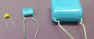
For comparative studies, experts selected three types of capacitors produced by TEARO with a nominal capacity of 470 μF and a maximum operating voltage of 16 V: miniature aluminum electrolytic capacitor for general use (Miniature Aluminum Electrolytic Capacitor) of the SK series; electrolytic low impedance with increased durability (Aluminum Electrolytic Low Impedance & Long Life Capacitor) TA series; solid-state aluminum with conductive polymer (Conductive Polymer Aluminum Solid Capacitor) CG series. The listed capacitors were compared both with each other and with tantalum capacitors produced by third-party companies (Tantalum Capacitor), conventionally designated in the figures by the TT index. In some cases, the capacitance of tantalum capacitors and comparable analogs differed from 470 μF, as reported in the original data of the experiments.
It should be noted that SK series capacitors are manufactured with the widest possible choice of both the required voltage (6.3...500 V) and capacitance (1...22000 µF). For CG series capacitors, this choice is much smaller - 2.5...25 V and 10...2200 µF, respectively. The range of operating voltage and rated capacitance of low-impedance long-life capacitors is 6.3...35 V and 33...8200 µF. Tantalum capacitors are manufactured with a permissible operating voltage of 2.5...63 V and a capacity of 0.1...2200 µF. The nominal capacitance of all capacitors is measured at a frequency of 120 Hz at an ambient temperature of 20 °C. With an increase in the operating frequency, which must be taken into account in the design of the SMPS, the capacitance of the capacitors changes significantly, and in different ways for different types. The overall dimensions of all capacitors selected for comparative evaluation are approximately the same.
To take into account the leakage current of the compared analogues, the table shows some empirical formula, the same for tantalum and aluminum capacitors with liquid electrolyte. The capacitance value is substituted into the formula in microfarads, and the voltage in volts. If the result of the calculation exceeds 3 μA, then engineering calculations are guided by this maximum possible value. The leakage current can be determined practically by applying operating voltage to the capacitor at least 2 minutes before measurements. For a polymer capacitor, the leakage current can be tens of times greater than that of analogues, but not more than 300 μA.
The cost indicators given in the table should be taken as indicative, since they are subject to changes due to market considerations. But the general trend is that aluminum capacitors with liquid electrolyte have the lowest price. Approximately twice as high for low-impedance electrolytic ones, and six times higher for polymer ones. This price ratio is quite justified, and we will see this from the results of measurements of electrical parameters. If we are guided only by such an important parameter as the equivalent series resistance (ESR), and the designer, when designing a switching power supply, is faced with the task of ensuring minimal ripple of its output voltage, then there will be two possible solutions: either use one polymer capacitor, or at least 10 similar aluminum with liquid electrolyte. Obviously, the second option can be adopted in low-responsibility projects. Where reliability of the power supply and thermal stability of the parameters of the designed device as a whole are required, the use of solid polymer capacitors seems to be the most rational. Let's take a closer look at this aspect of design using practical examples.
Influence of capacitor ESR on power supply parameters
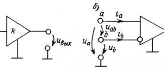
Rice. 3. Scheme for switching on the capacitor in operating mode
A comparison of the ESR of a solid-state polymer capacitor with other analogues shows that it is minimal and amounts to 11 mOhm. It is measured at a standard frequency of 100 kHz at a temperature of 20 °C. The ESR of a low-impedance capacitor is 8 times greater, and for an aluminum one it increases twentyfold. Moreover, in contrast to solid-state polymer, for selected analogs, EPS is measured at a frequency of 120 Hz, which will further deteriorate their performance at operating frequencies of tens of kilohertz. This parameter strongly depends on the capacitance of the capacitor, operating frequency and materials used in the manufacture. This property of capacitors will be discussed in more detail below.
In order to understand the importance of this parameter, let us turn to Fig. 3, which shows the connection circuit of capacitor C and its equivalent equivalent circuit. the ESR as a separate resistor R , and the equivalent series inductance (ESI) as a separate inductor L. A capacitor is connected between a switching mode power supply (SMPS), which converts 12V to a lower 5V, and some load made up of digital integrated circuits (ICs).
In the operation of a step-down SMPS, two half-cycles can be observed, which affects the output voltage of the SMPS, as shown in Fig. 4. During the first half-cycle, a certain portion of electrical energy is transferred to the storage capacitor C1 and in parallel to the IC load, while the pulsating voltage across the load and the filtering aluminum capacitor with liquid electrolyte increases from 4.93 to 5.07 V (Fig. 4a). In the second half-cycle, the SMPS output is disconnected from the load, and it is powered by the energy accumulated by the capacitor, while the ripple voltage decreases from 5.07 to 4.93 V. Thus, the ripple range is 140 mV, while the average level The output voltage supported by the regulation system in the SMPS corresponds to the required value of 5 V.
Rice. 4. Oscillograms of output voltage ripple with different types of filter capacitors
Operating voltage ripple should be taken into account when selecting a capacitor. The margin of the maximum permissible operating voltage, taking into account ripple, as shown in the table, is set with a coefficient of 1.15 from the nominal value for a solid-state polymer capacitor and 1.25 for the rest, which is 18.4 and 20 V, respectively.
Another oscillogram (Fig. 4b) shows how the output voltage ripple will change if, instead of an aluminum capacitor with a liquid electrolyte, a solid-state polymer capacitor of the same nominal capacitance of 470 μF is used. It is clearly noticeable here that the ripple range has sharply decreased - from 140 to 30 mV. This fact can be given a simple explanation if we look at Fig. 3. Since the ESR of the capacitor is connected in parallel with the load, the DC component of the current I= passes to the load directly without sensing the presence of the capacitor. But on the ripple, that is, the alternating component of the current I~, the EPS has a shunting effect, diverting the main part of it to the common power wire, as shown in the figure. The smaller the EPS, the stronger the shunting, which is confirmed by a comparison of Figures 4a and 4b.
It should be noted that when changing the filter capacitor, not only the range of pulsations changed, but also the shape. At the same time, very sharp needle-like voltage surges remain approximately equal. The reason for their presence is due to the presence of EPI in the capacitors, shown as a separate choke in Fig. 3. A sharp change in the current during its pulsation generates a self-induction EMF voltage on the EPI, superimposed on the output voltage. At large ESR, the relative contribution of needle-shaped fragments in voltage pulsations is hardly noticeable, and the overall shape of the pulsations is sawtooth-shaped. At small EPI, the relative contribution of EPI increases, so the pulsations, instead of sawtooth, acquire an exponential shape. Therefore, by observing the shape of the output voltage ripple, we can draw a definite conclusion about the influence of the ESR value of the used capacitors on this SMPS parameter and select the best one.
As shown in Fig. 3, high-frequency current ripples are generated not only in the SMPS. The IC load, which generally combines a number of digital devices (switch, flip-flop, coincidence circuit, counter, shift register, etc.) is non-stationary. During the operation of individual elements in the IC, significant pulse currents i~ can also arise, and if the ESR of the filter capacitor is not small enough, shunting secondary noise will be ineffective. In this case, interfering signals from the IC will be able to penetrate other nodes connected to a common SMPS and cause a failure in the operation of the device as a whole. Therefore, in critical design cases, the designer must consciously select a filter capacitor so that it reliably suppresses current ripple from both the SMPS and the load side.
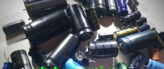
Set of electrolytic SMD capacitors
Hi all!!! What everyone has been waiting for for so long has happened, a review of capacitors)), written in continuation of the topic about the “radio amateur’s chest.” So, we will talk about electrolytic aluminum SMD capacitors. As I already said, I try to make most of my “ready-made solution” circuits in SMD design, where the circuit design allows it. The advantages are obvious: 1. Much smaller dimensions and weight of the finished device. 2. Minimization of parasitic capacitances and inductances, which sharply reduces induced interference (important in high-frequency nodes). 3. Allows you to significantly reduce the cost of the product. 4. And I just like to solder SMD components.
In what units are electrolytes used?
Direct voltage application:
— High-voltage capacitive energy storage devices with fast discharge, used in electrophysics, pulsed light sources, for magnetizing hard magnetic materials, in pulse generators for testing powerful electrical machines for resistance to shock loads and in other installations with discharge pulse durations from tens of microseconds to tens of milliseconds.
— To provide high current: in welding machines, X-ray machines, copying equipment and electrical discharge machining devices. — For high voltage direct current: Together with the rectifier, the electrolytic capacitor forms a constant voltage source for use in power electronics devices, variable frequency drives and power supplies. — In integrator circuits and sample-and-hold devices: for any analog memory circuit or analog sweep circuits. Application on direct voltage with a superimposed alternating component (pulsating voltage):
- In bandpass filters: in combination with resistors and inductors, they form filters for isolating a certain frequency band from a signal, filtering the DC component, etc. tasks. — For shunting electronic circuit components via alternating current. — For connecting sections of the circuit via alternating current with separation of the direct component. — In relaxation generators: together with resistors and active components to generate sawtooth and square wave voltages. — As part of rectifiers.
For AC voltage:
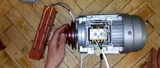
— To improve the quality of energy consumed from the AC network and the power factor of the equipment: by storing and releasing electrical energy, the aluminum electrolytic capacitor decouples the load and the supply network by instantaneous and reactive power. This improves the quality of power supply to the load and, at the same time, creates the prerequisites for obtaining an equipment power factor close to 1.0. — For low-pass power LC filters: improves the electromagnetic environment in circuits using thyristor rectifiers and inverters. — As a starting capacitor: to improve the starting performance of an asynchronous motor powered from a single-phase AC network.
As you can see, the scope of application is simply huge, in other words, it is used in almost any device.
A little theory about the design.
Two tapes of condenser paper are sandwiched between two tapes of specially treated aluminum foil, this combination of four tapes is rolled into a roll. The paper serving as a separator for aluminum electrodes is impregnated with an electrically conductive solution. Leads are connected to the electrodes, forming the active element of the capacitor. It is placed in a cylindrical aluminum housing with mechanical sealing of the terminals.
In cross section it looks like this
Let's check if this is true by dissecting one of the capacitors. Remove the plastic lining.
By the way, the body itself is made of aluminum, but covered with a dielectric film.
Let's move on.
Inside is really a roll of aluminum foil with a dielectric. Only the color is kind of gray after processing.
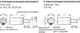
The rating and marking of such capacitors are determined as follows:
*Marking for 6.3V: “6V” **For size 6.3x7.7 tolerance L=0.3; for D= 8, 10 mm tolerance L=0.5 *** Code, capacitance and voltage designation for D= 8, 10 mm is made on the side surface
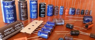
These containers are sold in a set, which consists of 13 denominations of 10 pieces each. Supplied in such tapes.
Additional photo from the site
Ratings and technical characteristics:
Operating voltage range: 10-50 V Operating temperature range: -40 … +85°C Error tolerance: It’s interesting here, the website states ±10%, but judging by the markings, different ratings have different tolerances up to ±20%. Some could not be identified at all. Most likely, most of them are no-name and produced in China. Operating time: Could not be determined because manufacturer is unknown. But I think it will be at least 2000 hours.
Let's start testing.
Capacitance measurements were made with an E7-22 device; to determine ESR, I used a “yellow-plated T4”. The results are in the table.
Conclusions:
In general, these capacitors are suitable for general use circuits and will work. But I don’t recommend installing it in critical components, as well as in precision circuits (since the manufacturer is unknown and there is no datasheet). For this, there are “branded” containers with improved characteristics. Quantity and denominations correspond to the seller's description.
Bonus for those who are very hot right now
Local dunes
Filmed on February 12))
The product was provided for writing a review by the store. The review was published in accordance with clause 18 of the Site Rules.
Assessing the influence of case temperature on the main parameters of the capacitor
The table shows the values of the maximum permissible current ripple in the selected capacitors, which are 0.4 A for an aluminum with liquid electrolyte, 0.84 A for a low-impedance and 5 A for a solid-state polymer capacitor. The effective value of the current appears here. Noteworthy is the significant difference in this indicator for different types of capacitors, approximately the same in size. And it can be quite reasonably assumed that in this case the main role is played not by the dimensions, but by the equivalent series resistance, which varies so much depending on the type of capacitor and its capacitance.
Rice. 5. Temperature dependence of the correction factor for permissible current ripples
If the basis for limiting the voltage on a capacitor containing ripples is the danger of electrical breakdown of a thin dielectric oxide film, as discussed earlier, then when limiting current ripples, another criterion related to thermal destruction is taken into account. We will talk about the negative impact of increased operating temperature on the durability of the capacitor a little later. Now we’ll just explain how the heating of a capacitor by current pulsations is taken into account and normalized.
It is known that when current I passes through a resistor with resistance R, electrical power P is released on it, measured in watts. This relationship is also valid in relation to the capacitor, if we take into account that the effective value of current ripple in amperes is substituted for the current, and the equivalent series resistance is substituted in ohms (so that the power is measured in watts), and not milliohms, as before. The pulsation power released on the capacitor leads to an increase in the housing temperature by ΔT degrees, which is determined [2] by the formula:
ΔT= I2R/AH
where A is the effective cooling surface of the condenser, depending on its size, cm 2; H is the thermal radiation coefficient, numerically equal to approximately 1.5...2 mW/cm2 °C. As can be concluded, the temperature gradient in the space adjacent to the capacitor is directly proportional to the ESR value and the squared effective value of current ripple and inversely proportional to the effective cooling surface of the capacitor.
Rice. 6. Temperature dependence of the correction factor for the permissible operating voltage
It is generally accepted that the operating conditions of the capacitor are quite acceptable if the temperature difference between the housing and the environment does not exceed 5 °C. It is from these considerations that the maximum current ripple value given in the table is calculated. However, it is quite clear that the conditions for heat dissipation at ambient temperatures of 25 and 85 ° C are somewhat different. Therefore, to take into account the influence of the maximum permissible current pulsations on the heating of the capacitor, an additional correction factor is introduced, the graphical dependence of which on temperature is shown in Fig. 5.
Let's assume that several filter capacitors with a capacity of 100 μF and a maximum operating voltage of 10 V applied at the output of the SMPS should dissipate current ripple with an effective value of 3000 mA. The temperature inside the SMPS housing is 95 °C. Since the permissible ripple current for a polymer capacitor is 2320 mA, taking into account the correction factor, this value, as shown in the figure, will not change at elevated temperatures. Consequently, two polymer capacitors with a large margin will provide the required SMPS reliability. In the case of using similar tantalum capacitors, we take into account that at room temperature they are capable of dissipating a ripple current of 1149 mA, and at a temperature of 95 ° C a temperature coefficient of 0.9 should be taken into account. As a result, the permissible current ripple for them will be 1034 mA, and to neutralize the ripple of 3000 mA, at least three tantalum capacitors will be required, which is obviously unprofitable from both a reliability and economic point of view. The cost of tantalum capacitors can be several times higher than that of polymer analogues.
Rice. 7. Temperature dependence of the relative change in capacitance
The temperature correction coefficient should also be taken into account when choosing the maximum permissible operating voltage of the capacitor, for which the diagram in Fig. 6. If, for example, to power a certain device it is necessary to use a SMPS with an output voltage of 10 V at an ambient temperature of 95 ° C, in this case, without the slightest damage to reliability, solid-state polymer capacitors with a maximum permissible operating voltage of 10 V can be used, and in no case - tantalum, for which the correction temperature coefficient at a given temperature of 95 ° C is equal to 0.92, that is, the permissible voltage will drop to a value of 10•0.92 = 9.2 V. If the maximum operating voltage for tantalum capacitors at temperature of 85 °C should be chosen equal to 16 V, then at 95 °C the permissible voltage will be 16•0.92 = 14.72 V, which fully satisfies the experimental conditions. However, the thermal stability of the tantalum capacitor is not taken into account here, which will be explained later, so in harsh conditions the use of only polymer capacitors is justified.
Changing the case temperature also leads to a change in the nominal value of the capacitance of aluminum capacitors with liquid electrolyte, and has almost no effect on the low-impedance and solid-state polymer capacitor, as illustrated in Fig. 7 for 15 µF capacitors at 100 kHz. Even at a temperature of –30 °C, an aluminum capacitor reduces its capacity by 25%, which makes it impossible to use it in conditions of negative temperatures. A low-impedance capacitor in terms of thermal stability of the nominal capacitance is slightly superior to a solid-state polymer one, but the choice of the latter is more preferable, since it is much superior to low-impedance EPS in terms of thermal stability, as clearly evidenced by Fig. 8. The figure shows diagrams of changes in the ESR of three capacitors with a capacity of 15 μF at a frequency of 100 kHz. When the housing temperature decreases from 25 to –20 °C, the ESR of an aluminum capacitor with liquid electrolyte changes in the range of 1.5...7 Ohms (increases by 4.7 times), low-impedance 0.68...0.9 Ohms (increases by 32%) , for solid-state polymer does not change and is 18 mOhm.
Rice. 8. Temperature dependence of equivalent series resistance
Now let's turn to Fig. 3, and repeat the measurements with a solid polymer capacitor with a capacity of 470 μF and a maximum operating voltage of 16 V. The result of this measurement repeats that obtained earlier (Fig. 4b). We emphasize that these measurements were carried out at room temperature 25 °C. At the next stage of research, due to external cooling, we will reduce the temperature of the condenser to –20 ° C, and note that the pulsation range remains the same. Instead of a polymer capacitor, we will try to use three aluminum capacitors with a liquid electrolyte with a capacity of 470 μF, connected in parallel. At room temperature, voltage ripple is illustrated in Fig. 9a. Let's cool the capacitors again (Fig. 9b), and, as we see, the pulsation range increases by more than 2 times. Based on the measurements taken, we can conclude: using several capacitors with a liquid electrolyte instead of one polymer one makes it possible to obtain commensurately small voltage ripples, however, at negative temperatures they increase unacceptably due to changes in the capacitance and ESR of the latter, which precludes their use in critical projects.
Rice. 9. Effect of temperature on voltage ripple in a capacitor with liquid electrolyte
The detailed consideration of the influence of temperature on the parameters of capacitors discussed above confirms that the most thermally stable among them is solid-state polymer. However, in this case, the influence of frequency was only indirectly affected, so we will dwell in more detail on the frequency stability of the parameters.
Advantages of polymer capacitors
With all the differences in design and materials, all four Panasonic polymer families of capacitors also have a common number of important advantages in comparison with other types of electrolytic capacitors popular today.
Excellent frequency response
Due to their very low ESR, all polymer families have a reduced impedance in the resonant frequency region, which allows them to pass increased pulse current in power circuits. During testing, it turned out that the peak pulse voltage when filtering interference (AC Ripple) is five times lower than with conventional tantalum capacitors, which also have a low ESR.
Rice. 6. Smoothing of current ripples at the power supply output
Self-healing mechanism
The self-healing mechanism inherent in polymer capacitors helps ensure increased reliability and safety in difficult operating conditions at elevated temperatures.
It happens that during voltage overloads, as well as due to random mechanical influences, a dielectric breakdown occurs in a conventional electrolytic capacitor, causing the capacitor to fail, sometimes with complete destruction and dangerous consequences in the form of fire.
It can be said that the self-healing mechanism inherent in polymer capacitors eliminates the consequences of dielectric breakdown due to self-isolation of the damaged area that occurs when the polymer is heated by the directly arising short-circuit current.
Therefore, for polymer capacitors, operating conditions at 90% of the maximum voltage are guaranteed to be acceptable. Whereas for conventional tantalum capacitors, safe conditions are chosen with an operating voltage margin of 50% or higher.
Stable capacity
The main parameter of capacitors is the electrical capacitance; it remains unchanged or almost stable in polymer capacitors at increased bias voltage DC Bias (Figure 7), as well as with temperature changes (pattern and frequency. In this respect, polymer capacitors compare favorably with ceramic ones, which can lose up to 90% of the nominal capacity.
Rice. 7. Change in capacitance of capacitors depending on bias voltage
Rice. 8. Change in capacitance of capacitors depending on temperature
Polymer capacitors do not cause the inherent acoustic noise of multilayer ceramic capacitors (MLCCs). The cause of ceramic noise is the piezoelectric effect when voltage with periodically changing polarity is applied to the terminals. Because of this, the capacitor generates slight vibrations that spread throughout the circuit board, as shown in Figure 9.
Rice. 9. Polymer capacitors do not cause acoustic noise
Table 2 shows the best parameters for Panasonic polymer capacitors.
Table 2. The best parameters of Panasonic polymer capacitor families
| Best setting | Maximum voltage, V | Maximum capacity, µF | Minimum ESR, mOhm | Smallest size |
| Meaning | 100/80 | 2700 | 3 | Size 2012 |
| Name | OS-CON/Hybrid | OS-CON | SP-Cap | SP-Cap |
Life time
Conventional electrolytic capacitors have a rather limited service life due to the drying out of the liquid-like electrolyte. The polymer electrolyte does not have the same aging problems, and capacitors have an extended service life even at elevated operating temperatures.
Tables 3 and 4 show the stated service life for Panasonic polymer electrolytic capacitors.
Table 3: Panasonic Hybrid Capacitor Lifespan
| Hybrid capacitors | |
| Temperature, °C | Service life, hour. |
| 125 | 4000 |
| 115 | 8000 |
| 105 | 16000 |
| 95 | 32000 |
| 85 | 64000 |
| 75 | 128000 |
Table 4. Service life of Panasonic OS-CON, SP-Cap and POSCAP capacitors
| OS-CON, SP-Cap, POSCAP | |
| Temperature, °C | Service life, hour. |
| 125 | 1000 |
| 105 | 10000 |
| 85 | 100000 |
A decrease in the operating temperature of hybrid capacitors for every 10°C causes a twofold extension of the service life. And for the OS-CON, SP-Cap and POSCAP families, a decrease in operating temperature for every 20°C leads to a tenfold extension of this parameter.
The influence of frequency on capacitor parameters
In Fig. Figure 3 shows the generally accepted equivalent circuit of a capacitor, which includes electrical capacitance, EPS and EPI. The need for real accounting of ESR and EPI in capacitors arose after the circuit design of power supplies (PS) in both industrial and consumer electronics underwent a qualitative leap. The previously used low-frequency power supply with transformers operating at a frequency of 50 Hz, over the course of a decade, was almost universally replaced by power supply due to their more advanced weight and size characteristics and higher efficiency. However, the principle of pulsed energy conversion at frequencies of tens of kilohertz suggested that the operating frequencies of filter capacitors should increase significantly, since the spectral components of such switching pulses are located in the range of hundreds of kilohertz - units of megahertz.
To do this, it was necessary to take into account the total resistance of the capacitor Z, the nature of the change of which with frequency f is determined by the capacitive component XC=1/2πfC and the inductive component XL=2πfL, as shown in Fig. 10. Since the capacitance of a capacitor is inversely proportional to frequency, it decreases with increasing frequency.
Inductive, directly proportional to frequency, on the contrary, increases. There is also a certain resonant frequency fres, at which the capacitive component of the resistance is equal in magnitude to the inductive one. The phenomenon of resonance determines the nature of the change in the impedance modulus, which includes the geometric sum of all components - active R = ESR and reactive XL, XC:
Geometric summation can be performed in the figure by adding the individual graphical components and making sure that the modulus of the impedance first decreases monotonically, then stabilizes at a level close to the equivalent series resistance, after which it begins to increase.
Rice. 10. Qualitative characteristics of the frequency dependence of the capacitor impedance
By substituting the parameters of the compared low-impedance and polymer capacitors into the above formula, you can obtain a diagram of the change in the modulus of their impedance, shown in Fig. 11. But this, so to speak, is a “theoretical product” that does not take into account that the capacitance of capacitors is by no means stable with a change in frequency. In practice, this dependence is very strong, especially for a tantalum capacitor, as illustrated in Fig. 12. Aluminum capacitors with liquid electrolyte, which are inferior to tantalum in their parameters, do not make sense to consider in this aspect. Comparing the graphs for polymer and tantalum capacitors, we see that at a frequency of 1 kHz the capacitance of a tantalum capacitor decreases by almost 13%, at 10 kHz - by 27%, and when the frequency reaches 100 kHz - it decreases by 2 times! Can such a capacitor be used in critical projects? The answer is quite expected.
Rice. 11. Effect of temperature on the impedance of a tantalum and polymer capacitor
Under the same conditions, a solid-state polymer capacitor almost does not change its capacitance and has an undeniable advantage over analogues both in the frequency stability of its parameters and in temperature, as discussed in the previous section of the article. But at the same time, the issue of the influence of temperature on the durability of capacitors was not addressed in any way. Let's take a closer look at it.
The effect of temperature on the durability of capacitors
Rice. 12. Frequency dependence of the capacitance of a tantalum and polymer capacitor
As established by many years of research, the durability of oxide capacitors is determined by the temperature of the housing, which depends both on the temperature of the surrounding air (external heat) and the heat generated inside the capacitor (internal heat). External heat causes accelerated degradation of the elements that form the capacitor (Fig. 1) - the rubber sealing disk, electrolyte, aluminum plates, as well as evaporation of the electrolyte, as mentioned earlier. These destructive processes are accelerated by internal heat, the main source of which is the dissipation of current pulsations on the EPS of the capacitor, discussed in detail in the previous section. This is how a certain vicious circle of negative processes is created, mutually accelerating each other: heat causes deterioration in the parameters of the capacitor, deterioration in parameters leads to an increase in the temperature of the capacitor.
Table 2. Dependence of the durability of capacitors on operating temperature and current ripple
The rate of degradation processes in a solid polymer capacitor is much lower than in capacitors with a liquid electrolyte, since the resistance of the polymer is incomparably higher. We will calculate the durability of capacitors depending on operating conditions using an Excel spreadsheet based on auxiliary materials from TEAPO specialists . Starting from the maximum permissible operating temperature of 85 ° C for aluminum capacitors with liquid electrolyte and 105 ° C for solid-state polymer ones, in our calculations we will lower the operating temperature in steps of 10 ° C, while simultaneously changing the operating current ripple at the level of 25%, 50%, 75% and 100% of the maximum permissible value. The calculation results are presented in Table 2. Analyzing the data obtained, one can be convinced of the undoubted advantage of solid-state polymer capacitors, since under any conditions their durability is 3...6 times higher compared to capacitors based on liquid electrolyte. And the initial conditions themselves for polymer capacitors are incomparably more difficult. For example, the maximum hard mode for capacitors with a liquid electrolyte corresponds to a temperature of 85 ° C and a current ripple of 0.4 A, and for polymer capacitors - 105 ° C and 5 A. A similar conclusion can be obtained by analyzing the diagrams in Fig. 13. Here, the irreversible decrease in capacitor capacity during operation is taken into account and it is believed that the capacitor must be replaced when the capacitance decreases beyond the limits allowed by technical specifications (TS) - 10 or 20%.
Table 3. Solid polymer capacitors from TEARO
Rice. 13. Temperature dependence of the durability of tantalum and polymer capacitors
Summarizing the comparative analysis of the parameters of three types of capacitors that differ in manufacturing technology, we can conclude that there is an undoubted advantage in the parameters of the CG series polymer capacitor. TEAPO company also produces many other series of polymer capacitors, but it is simply impossible to cover them in detail in one article, so we will limit ourselves to only a general description.
Main parameters of tantalum capacitors
Calculation of safe operating modes involves determining the levels of permissible voltages and currents [3]. This calculation will require the use of the basic parameters of tantalum capacitors, which can be found in the documentation for the relevant components.
Nominal capacity (“ Capacitance ”).
Tantalum capacitors have a high specific capacitance, which can be explained quite simply. As you know, the capacitance of a capacitor is determined by the formula:
C = εrε0S/d, (1)
where εr is the dielectric constant of the material, ε0 is the electrical constant, S is the area of the electrodes, d is the thickness of the dielectric.
The dielectric (Ta2O5) has a high dielectric constant ε=26 (Table 2) [1]. In addition, the anode surface itself in the capacitor structure is granular and has a large area. As a result, the capacitance of tantalum capacitors is hundreds and thousands of microfarads (Table 3).
Table 2 - Dielectric constant of various materials
| Dielectric type | Dielectric constant, ε |
| Air (vacuum) | 1.0 |
| Paper | 2.0 … 6.0 |
| Plastic | 2.1 … 6.0 |
| Mineral oil | 2.2 … 2.3 |
| Silicone oil | 2.7 … 2.8 |
| Quartz | 3.8 … 4.4 |
| Glass | 4.8 … 8.0 |
| Porcelain | 5.1 … 5.9 |
| Mica | 5.4 … 8.7 |
| Al2O3 | 8.4 |
| Ta2O5 | 26 |
| Ceramics | 12 … 400000 |
Table 3 – Nomenclature and parameters of tantalum capacitors series 293D (Vishay)
| Capacity. µF | 4 V | 6.3 V | 10 V | 16 V | 20 V | 25 V | 35 V | 50 V | 63 V | 75 V |
| 0.10 | A | A | A | A | ||||||
| 0.15 | A | A/B | B | |||||||
| 0.22 | A | A/B | B | |||||||
| 0.33 | A | A.A. | A/B | B | ||||||
| 0.47 | A | A | A | A/B | A/B/C | B | ||||
| 0.68 | A | A | A | A/B | B/C | C | ||||
| 1.0 | A | A | A/B | A/B | A/B | B/C | D | |||
| 1.5 | A | A | A/B | A/B | A/B | B/C | B/C/D | D | ||
| 2.2 | A | A | A/B | A/B | A/B | A/B/C | B/C | B/C/D | D | |
| 3.3 | A | A/B | A/B | A/B | A/B/C | A/B/C | B/C/D | C/D | D | |
| 4.7 | A/B | A/B | A/B/C | A/B/C | A/B/C | A/B/C/D | B/C/D | C/D/E | D | E |
| 6.8 | A/B | A/B | A/B/C | A/B/C | A/B/C | B/C/D | C/D | D/E | ||
| A/B | A/B/C | A/B/C | A/B/C/D | B/C/D | B/C/D | C/D | D/E | E | ||
| A/B/C | A/B/C | A/B/C | B/C | B/C/D | B/C/D | D/E | E | |||
| A/B/C | A/B/C | A/B/C/D | B/C/D | B/C/D | C/D/E/V | D/E | ||||
| A/B/C | A/B/C | B/C/D | B/C/D | C/D | D/E | |||||
| A/B/C | A/B/C/D | B/C/D | C/D/E | D/E | D/E | |||||
| B/C/D | B/C/D | B/C/D/E/V | D/E | D/E | E | |||||
| 100 | A/B/C/D | B/C/D/E | B/C/D/E/V | D/E/V | D/E | |||||
| 120 | D | D | E | |||||||
| 150 | B/C/D | C/D/E | C/D/E | D/E | ||||||
| 220 | B/C/D/E | C/D/E | D/E/V | E | ||||||
| 330 | D/E | D/E | D/E | |||||||
| 470 | D/E | D/E | E | |||||||
| 680 | D/E | E | ||||||||
| 1000 | E | E |
Rated Voltage.
Modern solid tantalum capacitors are available for rated voltages up to 75 V (Table 3). It should be noted that one feature of this parameter is that for normal operation as part of various devices, tantalum capacitors must be used at voltages lower than the rated voltage [4].
This rule appeared in the 50s, and was associated with the peculiarities of military acceptance of tantalum capacitors, and the procedures for determining reliability established at the same time. These standard tests involved a reliability test with the capacitors held at rated voltage for 1000 hours, a temperature of 85°C and a current limiting resistor of less than 3 ohms. Acceptance “M” implies that the number of failures per 1000 hours does not exceed 1%. Both military and commercial components have been designed to meet the requirements of this standard.
These conditions remain the industry standard to this day, but modern low-impedance circuits (with minimal limiting resistance) require higher reliability than "M" acceptance provides. Since data on failure rates has recently become available (mostly data on military electronics), it has become possible to carry out actual calculations and create a new standard, Mil-Std-217, which takes into account the requirements of all types of capacitors.
Research has shown that to improve reliability it is necessary to reduce the operating voltage. Reducing the operating voltage to 50% of the rated voltage RV (“Rated Voltage”) leads to a reduction in the FIT (“Failures In Time”) rate to 5% (Figure 6).
Figure 6 – Reduction in the number of failures when operating voltage is reduced
The total resistance of an aluminum electrolytic capacitor (impedance).
As is known, the equivalent equivalent circuit of a capacitor (Figure 7), in addition to the capacitive component, contains a number of additional elements:
- inductive component (L), which takes into account the inductance of the leads;
- parallel resistance (Rp), which allows you to take into account leakage current through the dielectric and surface leakage currents;
- series equivalent resistance (“Equivalent Series Resistance”, ESR).
Figure 7 – Capacitor equivalent circuit
The circuit impedance has a complex frequency dependence (Figure 8). The main feature of this dependence is the fact that with increasing frequency the impedance decreases down to the megahertz range. This allows the use of tantalum capacitors in modern power supplies operating at frequencies of 100 kHz and higher.
Figure 8 – Typical frequency dependence of impedance and ESR
Equivalent
Series Resistance ( ESR ) .
When operating on alternating voltage, the capacitor has a series resistance. At low frequencies this resistance is determined by the resistance of the dielectric (Ta2O5). At high frequencies, the resistance of the electrolyte (MnO2) begins to dominate. The typical frequency dependence determines the decrease in ESR with increasing frequency up to the megahertz range (Figure 8).
Since the resistance of manganese dioxide is inversely proportional to temperature, the ESR of a solid tantalum capacitor at high frequencies decreases with increasing temperature.
Maximum power dissipation (“ Power
dissipation ”).
When an alternating voltage is applied to a solid tantalum capacitor, the presence of series resistance produces heat according to the formula:
P = I²ESR, (2)
The permissible increase in the temperature of the capacitor due to the released power is determined experimentally. For example, a superheat value of 20°C is the maximum for standard tantalum chip capacitors. In turn, this overheating determines the maximum released power (Table 4).
Table 4 - Maximum power dissipation of 293D series capacitors
| Standard size | Maximum power dissipation (25°C). W |
| 0.075 | |
| 0.085 | |
| 0.11 | |
| 0.15 | |
| 0.165 | |
| 0.125 |
Having become familiar with the design, breakdown mechanisms and basic parameters of tantalum capacitors, it is possible to determine the main restrictions imposed on the operating levels of currents and voltages.
Review of TEARO polymer capacitors
The full range of capacitors produced by TEARO and a detailed description of the parameters can be obtained from the source [4]. Let us briefly get acquainted only with the solid-state polymers presented in Table 3.
Rice. 14. Overall dimensions of CG series polymer capacitors
Using the data given in the table, the designer, in accordance with the technical specifications for the project being developed, will be able to choose a type of solid-state polymer capacitor that will allow him to easily achieve the required technical parameters of the device. The ESR data for a particular capacitor represents a certain value in the interval shown in the table, and, as explained earlier, as the capacitance of the selected capacitor decreases, its ESR increases, and vice versa.
Rice. 15. Marking of polymer capacitors
The overall dimensions of solid-state polymer capacitors also vary greatly depending on the series, capacitance and maximum allowable operating voltage. We present data only for the CG series capacitors we used in testing (Fig. 14). Here, the case diameter D can take values from 4 to 10 mm, the lead diameter d is 0.45...0.6 mm, the body height H is 5.4...12.5 mm, the pin spacing P is 1.5...5±0 .5 mm. For other standard ratings, the required characteristics can be easily found in [4].
Capacitors are marked on the end side of the housing as shown in Fig. 15.
If the external examination does not produce results, we carry out testing using a multimeter
In any case, to perform this work it is necessary to desolder the part from the board. This must be done carefully so as not to pull the contact legs out of the housing.
If your device has a specialized connector for testing, diagnostics are performed in accordance with the instructions for the multimeter. The full range of testing (if such an algorithm is available) must be carried out. You need to connect correctly, observing the polarity. The marking must be present on the body of the part. With such a check, you will not only check the serviceability, but also see the capacity value.
- Checking the performance of a capacitor begins with measuring the resistance. This is done differently than with resistors or diodes. To understand the principle of testing, let us recall the basic properties of a capacitor. As charge accumulates, the resistance between the plates increases. First you need to discharge the element (remove the residual charge). Of course, this is only true for a working part. You just need to short the legs with any conductor, or close them together.
Important: electrolytic capacitors can operate with voltages of up to 600 Volts or more, so they are discharged only with a tool with an insulated handle.
- Then you need to set the measurement limit in ohmmeter mode to 2 MOhm. Connect the capacitor to the multimeter and observe the readings.
It is better to carry out measurements of this kind using a pointer instrument, this way the dynamics will be more clearly visible. But everything will be clear on the digital display. A working radio element will demonstrate a smooth increase in resistance. Moreover, the higher the capacity, the slower the process occurs. When the value is close to infinity, the digital indicator will show “1” (arrow, respectively, “∞”). - Why is this happening? The multimeter has a battery. When measuring resistance, voltage is applied to the part, which charges the capacitor. Next are the simple laws of physics: the capacitance has accumulated, the resistance has increased to infinity. If you close the contacts again in the “short” mode, the resistance will decrease sharply. Then it will smoothly recover ad infinitum.