Three options
Checking microcircuits is a rather complex process, which often turns out to be impossible. The reason lies in the fact that the microcircuit contains a large number of different radioelements. However, even in this situation there are several ways to check:
- visual inspection. By carefully examining each element of the microcircuit, you can detect a defect (cracks in the case, burnt contacts, etc.);
- checking power with a multimeter. Sometimes the problem lies in a short circuit on the part of the power supply; replacing it can help correct the situation;
- performance check. Most microcircuits have not one, but several outputs, so a malfunction of at least one of the elements leads to failure of the entire microcircuit.
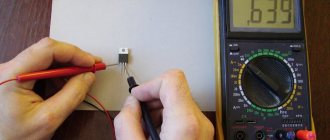
The easiest to check are the KR142 series microcircuits. They have only three pins, so when any voltage level is applied to the input, a multimeter checks its level at the output and draws a conclusion about the state of the microcircuit.
The next most difficult tests are the K155, K176, etc. series microcircuits. To check, you need to use a block and a power source with a specific voltage level selected for the microcircuit. Just as in the case of KR142 series microcircuits, we apply a signal to the input and monitor its output level using a multimeter.
First startup of the device and troubleshooting
After you have finished assembling your device and soldered the last element into the board, do not rush to turn it on right away. Prepare your multimeter, open the circuit diagram and description of the circuit.
First you need to check the correct installation, check for short circuit (short circuit). If you think that all the elements are soldered correctly, and you did not find a short circuit after testing, then you can clean the tracks from residual rosin and apply power, but first you should check the resistance of the power circuit, if it is suspiciously high, and if this is not specified in the package you are collecting circuit, then do not rush to turn on the circuit, double-check it again. Have you assembled the diode bridge correctly, has the polarity been observed when sealing capacitors in the power circuit, etc. If the device you are assembling consumes a large current, from 1 ampere and above, this indicates a short circuit or incorrectly soldered elements, there are exceptions, for example voltage converters They eat 2-3 amps at idle. You can connect a low-power constant resistor of several ohms in series with the power supply circuit; this can save the device from failure. If the circuit contains powerful transistors or microcircuits that are mounted on a radiator, do not forget to isolate them from each other. When initially turning on devices, be careful as diodes and electrolytic capacitors may explode if turned on incorrectly or overvoltage. Moreover, capacitors usually do not explode immediately, but first heat up for some time. Do not leave devices turned on and not yet configured unattended.
troubleshooting
Probably every radio amateur has encountered the case when, after power is applied, the assembled device does not want to work, or works intermittently, not as it should. If you rule out errors in installation, then you can read on, but if you drew the tracks for the board yourself, then run to check the printed circuit board!
Before you start troubleshooting, if the device you are repairing is not familiar to you, you first need to get as much information as possible about this device, what kind of device, or what kind of unit (power supply unit, amplifier, or other device), and you need to get a description and a diagram of this device. Before you take it out and start unscrewing the board, take a closer look to see if there is anything extra inside the case, a torn piece, a splinter, etc. Don’t forget to check even such circuit elements as a switch or power connector.
Before you start picking at the board, discharge all capacitors, including high-voltage ceramic ones; you need to discharge them with a resistor of about 100 Ohms. If you forget to do this, then in the event of an accidental short circuit, or even during dialing or soldering of radio components, the consequences can be terrible, more elements may fly off, and you yourself may suffer. It is very important!
The test always starts with power supply and voltage check, check the voltage in the network, the fuse, then the power supply. Check the voltage at the output of the power supply and, if possible, the output current. It happens that the voltage is normal, but if you connect a light bulb or resistor, the voltage drops sharply or completely, the power supply goes into protection. If it turns out that the voltage is lower than necessary or is not there at all, then we check the diode bridges, then the voltage stabilizer - if there is one, transistors, if they are present in the circuit. Sometimes even the simplest multimeter can find a fault in the circuit. Checking and troubleshooting should always be carried out with the power disconnected from the device! Pay attention to the wires, whether they are torn off or exposed. If the boards are connected to each other by connectors or wires that are secured in screw terminals, try reconnecting them. Screw terminals are not reliable and contact may be lost over time. Try to turn on the board again, watch carefully, feel the transistors, resistors, for heating.
So, in front of us lies a bare board with sealed radio components, take a magnifying glass and begin an external inspection of the radio elements, along the way you can even sniff, and this is not a joke, a burnt radio element can be identified immediately. It happens that such an element cannot be detected by external inspection. When inspecting, pay attention to the darkening of the resistors and transistors; if you notice such an element, then immediately unsolder it from the board and call it, even if the element is working, it is better to replace it. It happens that transistors even after they fail are called by the tester. You need to ring resistors and other radio components by desoldering them from the board. After inspecting the radio components, we turn the board over and begin an inspection from the side of the tracks to see if there are burnt out or short circuits (for example, if the leads of the radio elements are long, they can short out, so be careful when reassembling the equipment). Touch the elements, if you feel that the resistor is wobbly on the board, it is quite possible that the electrical contact has disappeared, re-solder it. If the board has thin traces, they should be checked for breaks and microcracks.
If you assembled the device, check whether all radio components are soldered correctly? Different transistors have different pinouts, and diodes may also have different designations. Open the manual for each soldered element (if you don’t remember the pinouts from memory) and start checking. Unfortunately, it often happens that when a radio element fails, the element itself may not outwardly differ in any way from a working one. If you still fail to find a fault in the circuit, you will have to unsolder and ring all the transistors and elements. Generally speaking, you can check circuits without unsoldering the elements, but for this you need at least an oscilloscope and a good multimeter. In this article I will not delve into the methods and techniques of working with an oscilloscope. If the circuit is simple, faulty elements are usually detected very quickly.
Microcircuits are usually checked for malfunction by replacing them with another one; when assembling circuits, I advise you to put special sockets under the microcircuits, this is very convenient in case you suddenly need to remove it. But if the microcircuit is without a socket, and it is soldered into the board, then I advise you to check the voltage at the power pins of the microcircuit before starting to unsolder it.
In circuits where a microcontroller is used, if after switching on the circuit shows no signs of life, and the installation is correct and the radio components are soldered correctly, first of all you need to try to reflash it. If an error occurred during programming or the “left” firmware was uploaded, such an MK will not work in the circuit.
If you don’t want to desolder, for example, a resistor, diode, or capacitor from the board (so that the tracks don’t heat up again, otherwise they might fall off) and you are sinning on it, you can try soldering a similar element in parallel to it. You can do this with capacitors, resistors, and diodes, just remember that if you parallel two resistors, your total resistance will be halved, so one terminal of the resistor from the board will still have to be unsoldered, and with capacitors, vice versa, when paralleling the capacitance increase, for example, if the circuit contains a 220 µF capacitor, solder 100 µF in parallel to it, this will do nothing if you turn on the device for a short time. As a rule, capacitors with resistors very rarely fail. As for transistors, they must be unsoldered; in no case can you install the same one in parallel with a conditionally non-working transistor.
In circuits where coils or miniature transformers with a large number of terminals are used, even with a tap from the middle, you need to respect the beginning and end of the turns; if, after starting such a circuit, the device does not want to work, swap the terminals.
If you think that you have found the reason why your device did not want to work and replaced this element on the board, before applying power, check the board at the solder points for short circuits. Put aside all metal objects, screwdrivers, resistors, pieces of wire, etc. God forbid, while supplying power and testing the device, a resistor rolls under the board and shorts out.
Task
Now I suggest you solve a small problem, below is a diagram of a fairly simple power supply, I deliberately made mistakes in this diagram and drew some elements incorrectly, try to find all the mistakes. Imagine that this is your device, which you assembled yourself, but after turning it on it did not work, or some elements failed.
Be very careful, there are a lot of errors here, imagine that this is a real device, if you do not find all the errors, the next time you turn on the device, something may fail again.
Using a special tester
For more complex checks, you need to use a special microcircuit tester, which you can purchase or make yourself. When dialing individual components of the microcircuit, data will be displayed on the display screen, analyzing which you can come to a conclusion about the serviceability or malfunction of the element. It is worth remembering that in order to fully test the microcircuit, you need to completely simulate its normal operating mode, that is, ensure the supply of voltage at the required level. To do this, the test should be carried out on a special test board.
Often, it turns out to be impossible to test a microcircuit without soldering the elements, and each of them must be called separately. How to ring individual elements of the microcircuit after desoldering will be discussed below.
Rules for safe calling using a multimeter
testing the network cable with a multimeter
Working with electricity does not allow for unprofessionalism, so a certain list of rules has been developed that make it possible to make it as accurate, fast and safe as possible.
When making calls, it is most convenient to use special tips at the ends of the measuring wires, which are more commonly known as “crocodiles”. They will make the contact stable and free your hands when taking measurements. When testing, the circuit being tested must always be de-energized (even low-current batteries must be removed). If there are capacitors in the circuit, they must be discharged by short-circuiting
Otherwise, the device will simply burn out during work. Before checking the integrity of a long length of conductor when taking measurements, it is important not to touch its bare ends with your hands. This is due to the fact that the resulting readings may be incorrect.
When testing a multi-core cable, it is necessary to separate and strip all existing cores from both ends. After this, you need to check the circuit for the presence of short circuits in it: to do this, a “crocodile” is attached to each core in turn, and all the remaining ones are touched with the other measuring end in all possible combinations.
Check to see if there is a short circuit between the cable cores. If the indicator shows “1” and there is no sound signal, then everything is in order, otherwise there is a short circuit.
In this case, a sound signal will indicate the presence of a short circuit between the tested conductors
This may not be of practical importance for small cross-section multi-core cables operating in low-current networks, but when working with high voltages it is fundamentally important
We call the cable cores. There is a sound signal - everything is fine, otherwise the core is damaged.
To determine the integrity of the cores, the same operation is performed, only at one end of the cable all stripped cores are twisted together
When searching for a break, it is important to consider that the absence of a sound signal at either end will indicate a violation of the integrity of the conductor
Transistors (field-effect and bipolar)
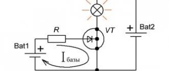
We switch the multimeter to the “testing” mode, connect the red probe to the base of the transistor, and touch the collector terminal with the black one. The display should show the breakdown voltage value. A similar level will be shown when checking the circuit between the base and emitter. To do this, connect the red probe to the base, and apply the black probe to the emitter.
The next step is to check the same transistor terminals in reverse connection. We connect the black probe to the base, and with the red probe we touch the emitter and collector in turn. If the display shows one (infinite resistance), then the transistor is working. This is how field-effect transistors are tested. Bipolar transistors are checked using a similar method, only the red and black probes are swapped. Accordingly, the values on the multimeter will also show the opposite.
Capacitors, resistors and diodes
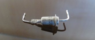
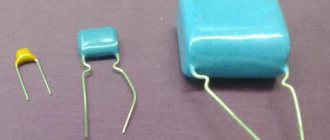
The serviceability of the capacitor is checked by connecting the probes of a multimeter to its terminals. Within a second, the resistance will increase from a few ohms to infinity. If you swap the probes, the effect will repeat.
To ensure that the resistor is working properly, it is enough to measure its resistance. If it is different from zero and less than infinity, then the resistor is working.
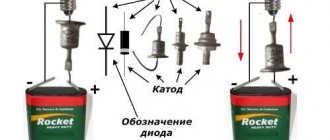
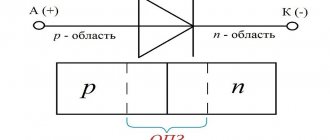
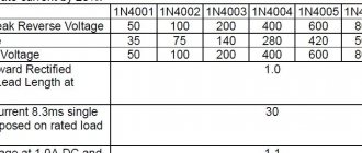
Checking diodes from a microcircuit is quite simple. By measuring the resistance between the anode and cathode in direct and reverse sequence (switching the multimeter probes), we make sure that in one case one is at the level of several tens to hundreds of Ohms, and in the other it tends to infinity (one in the “dialing” mode on the display ).
We check the wiring in the apartment with a multimeter
Let's take as an example a modern apartment in which the wiring is done in accordance with current requirements and standards. This means that when laying the lighting lines and power outlets, they were separated, and separate wires were laid for them in each of the rooms. Each of these circuits is powered from the apartment panel through a separate circuit breaker.
If the light has gone out in one of the rooms, you should first check that the lamp is working properly. Before starting work, it is necessary to turn off the power to the room/apartment depending on the power supply. When using an opaque incandescent lamp in a lamp, the integrity of the filament is difficult to visually determine, so you will need a multimeter and its continuity function. Let's figure out step by step how to do this correctly.
First you need to check the shield for triggered circuit breakers. In the first case, they will be in the on position (then the fault may be hidden in the room switch, lamp or socket). The likelihood of damage to the wiring in such a situation is low. If the device works, you will need to check everything except the room switch, including the switchboard itself.
If the machines don't work
We ring the switch. When the switch is on, there should be a sound signal, when off, there should be silence and “1” on the indicator.
- Make sure there is voltage at the input and output of the machine. If it is, you can proceed to further verification.
- Prepare the device for operation and check its serviceability by short-circuiting the measuring leads.
- Unscrew the lamp from the socket.
- Touch one of the measuring probes to the base (the metal part of the lamp with threads), and the second to the central contact of the lamp (the insulated center of the end part of the base).
- A sound signal and instrument readings that are different from 0 or 1 mean that the lamp is working. If it is faulty, you need to replace it, which will solve the problem.
- We check the cartridge for serviceability. To do this, you need to disassemble the lamp, make sure that the connected wires and contacts are intact. If everything is in order, then the cause of the failure is not in the cartridge. If malfunctions are detected, they must be eliminated. The lamp cannot be screwed in yet.
- We check the serviceability of the room switch. To do this, remove the plastic cover, unscrew the screws and take it out of the mounting box. We inspect the equipment for the appearance of carbon deposits and check the tightness of the fasteners. If everything is in order, you need to install the measuring ends of the tester on the contacts of the switch. The appearance of a sound signal when dialing in the on position will indicate that the equipment is working properly. The wires do not need to be disconnected.
During such a check, as a rule, a malfunction is identified, which becomes the cause of all the troubles. Eliminating it allows you to quickly solve the problem.
If the machine worked
To ensure electrical safety during work, in this case the voltage is turned off using a general apartment circuit breaker. Next, the serviceability of the socket and the wires connected to the lamp is determined according to the algorithm described above. If there are no faults, you need to check the wiring itself using a multimeter and the continuity function. Such malfunctions happen quite rarely, but they still happen, for example, when installing suspended ceilings or decorative interior elements.
The wiring in this case is performed as follows.
- Using a screwdriver, disconnect the connected conductor (if installed correctly, it is located at the bottom) and move it to the side. The “zero” of this group is, as a rule, located at the zero clamp under the machines.
- Unscrew the incandescent lamp from the socket. Using a ready-to-use tester, we check the line by connecting one of the measuring probes to “zero” and the other to the disconnected conductor. If the device beeps, it means the wiring is shorted.
- In this case, in the room under the ceiling above the switch, we find and open the junction box. We disconnect the wires.
- We check all groups of wires for short circuits. To determine the section of the circuit in which there is a short circuit, we again check the circuits on the apartment panel with a multimeter. If the signal sounds, it means that it is the wire laid from the switchboard to the box in the room that needs to be repaired. Otherwise, the search will need to be continued until a result is obtained.
Inductance and thyristors
Checking the coil for a break is carried out by measuring its resistance with a multimeter. The element is considered serviceable if the resistance is less than infinity. It should be noted that not all multimeters are capable of testing inductance.
The thyristor is checked as follows. We apply the red probe to the anode, and the black one to the cathode. The multimeter window should display infinite resistance. After this, we connect the control electrode to the anode, observing the drop in resistance on the multimeter display to hundreds of ohms. We disconnect the control electrode from the anode - the resistance of the thyristor should not change. This is how a fully functional thyristor behaves.