A few words about varieties
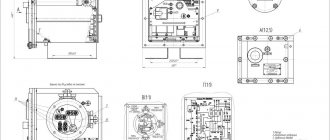
Electronic timers for setting delays for turning on and off are used in microwave ovens, washing machines, heating systems, for arranging a smart home, etc. The principle of operation of a time relay is based on setting a time interval for a delay in the operation of the electrical network. In practice, such a device can have different modes of deceleration:
- electromagnetic;
Rice. 1: electromagnetic time relays
- pneumatic;
- with clock mechanism;
Rice. 2. With clock mechanism
- motor;
- electronic.
Due to the complexity of setup and the shortage of certain elements, not all time relays can be assembled with your own hands. The simplest option for manufacturing and consideration are electronic models, since today you can get components for them both from old equipment and from any radio parts store.
Electromechanical relays and other options are available if specific components are available, which are not always available for sale.
What will be needed for production?
Depending on the chosen model, the process can be either simple or quite labor-intensive. Therefore, it is better to stock up on everything you need in advance, so as not to stop at half the work done.
To assemble a time relay you will need:
- a set of radio components - in each specific example of a homemade relay, their list will be different, but the basic nomenclature will remain unchanged (resistors, capacitors, transistors, microcircuits, intermediate relays or switches, power supplies or step-down transformers, coils, etc.);
- the basis for a set of elements - a printed circuit board, dielectric surface or frame, are also selected based on local conditions;
Rice. 3. Printed circuit board
- soldering iron, solder and other devices for connecting circuit elements.
- housing – to protect relay elements from various mechanical influences, dust, moisture and debris;
- control or programming unit - if you plan to make an adjustable delay.
In some situations, the above parts can be borrowed from old electronic devices if they suit you, otherwise you will need to purchase them. You can decide on a specific list after you choose the specific model you want to make.
We create a time relay for 12 and 220 Volts
Depending on the magnitude of the supply voltage to which the load is connected, the potential level under which the time relay elements will be located is also determined. In practice, to create time delays, both those operating from a 220V network and from a safe low 12V are used.
The first option is considered simpler, since the work is carried out directly from the network. Also, a 220 V circuit is relevant for powering particularly powerful loads - engines or household appliances.
Practical schemes
All proposed options for homemade relays contain inexpensive elements that are freely sold in any radio store. Their circuit works according to the simplest algorithm, according to which the timer built into it first starts, and at the end of the countdown the actuator unit is triggered. As a result, supply voltage is supplied or removed from the load connected to the relay.
Transistor timing device
Circuit with transistors
The electrical circuit of a time relay with several transistors is the simplest to implement, since it contains only 8 active elements. Based on it, it is possible to assemble devices that control the time when lights are turned off, for example. To power such a circuit, you will need a 9 Volt battery or a 12 Volt car battery.
To make a homemade relay, you need the following set of parts:
- two fixed resistors and one variable potentiometer - their values are selected for a specific circuit;
- dual transistor KT937A or foreign equivalent;
- load switching relay;
- constant timing capacitor of the required capacity;
- diode designated KD105B;
- button to start the relay.
The time delay in a homemade device is organized by charging a permanent capacitor to the power level of the transistor key element. During this entire process, until the voltage reaches 9-12 Volts, the output switch remains open, and the light bulb connected to it glows at full intensity. After a period of time specified by the current value of the variable resistor, the transistor is completely closed. As a result, the winding in its collector is de-energized, and the load is disconnected from the power circuit.
The time parameters in seconds or minutes for a relay assembled using a transistor circuit are selected experimentally by changing the resistance of an adjustable resistor. For the convenience of later setting the moment of switching on or off, it is recommended to put indicators on the relay body that indicate the time settings obtained experimentally.
Relay on a chip
Time relay on a microcircuit
The circuit of an electronic timer, assembled with your own hands on the basis of a microcircuit, allows you to get rid of such disadvantages of the transistor analogue as the difficulty of calculating the delay time. In addition, in a transistor circuit, each time before the next start it is necessary to discharge the timing capacitor. The use of microcircuits, on the one hand, eliminates these disadvantages, and on the other hand, somewhat complicates the device. When choosing a microchip suitable for a time relay, proceed from the following considerations:
- if you need a delay in the range from ten minutes to one hour, the TL431 series chip is best suited;
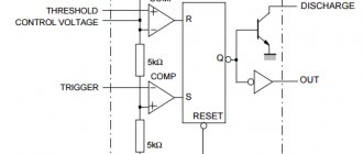
- if necessary, work with a wider range - with a time delay from 1 second to several hours - it is most convenient to make a timer on the classic NE555 series;
- Approximately the same timing parameters can be obtained using the KR512PS10 microcircuit.
Due to the presence of a reference voltage source, their response threshold is strictly fixed, which allows you to accurately set the required delay time.
The ability to increase the switching voltage allows you to increase the range of time delays upward. Due to the presence of a built-in charging circuit zeroing unit, there is no need to perform a forced reset. The advantages of this version of a homemade time relay include a reduction in false alarms, which is explained by more “strict” current modes.
Relay circuits based on microcontrollers have become very popular. However, they are not entirely convenient for self-copying. When using them, certain difficulties arise associated with soldering microchips and their programming. The proposed options for timing devices are usually enough for home repetition.
Device for switching equipment 220 Volt
220 V time delay relay
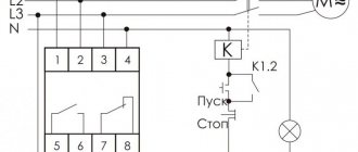
To control the operation of power equipment (electric motors, for example), conventional 12 Volt circuits are not suitable. In this case, a magnetic starter is required that switches voltages of 220 or 380 Volts (depending on the number of phases). To supply control voltage to its coil, you will also need a powerful 220 Volt driver.
The simplest circuit of such a relay, used only for lighting control, does not require powerful contactors and can be assembled from a limited number of parts. To do this, you will need a rectifier bridge of 4 valve diodes and a semiconductor thyristor controlled by the alternating voltage level. When operating as a regulator, the valve allows only the positive part of the 220 Volt sinusoid to pass through. This mode is permissible only for circuits loaded with incandescent light bulbs, as well as fan motors or heating elements. They are not sensitive to the shape of the supplied voltage, unlike other types of switched electrical equipment.
Variable resistor 1.5 kOhm
To assemble such a timer yourself, you will need the following components and parts:
- fixed resistances of 4.3 MOhm and 200 Ohm plus a variable resistor of 1.5 kOhm;
- four diodes designed for a current of over 1 Ampere and a reverse voltage of up to 400 Volts (this could be KD202R, for example);
- 0.47 µF timing capacitor;
- thyristor VT151 or a similar element.
The operating principle of the circuit is similar to the previously discussed cases and boils down to charging the timing capacitor with the supply voltage.
During the charging cycle, a positive potential is applied to the control electrode of the thyristor, maintaining it in the open state. As a result, half-waves of the mains voltage are supplied to the light bulb connected to the circuit. Upon completion of the charging process, the current in the circuit stops, the thyristor closes, and the light goes out. The time delay is adjusted by setting the voltage value on the charging capacitor using a variable resistor.
Idea 1. On diodes
Let's consider a version of the simplest logical element for operation in a 220V circuit.
Rice. 4. 220V time relay circuit
Here, switching on occurs when button S1 is pressed, after which voltage is supplied to the diode bridge. From the bridge, the potential passes to a timing element consisting of resistors and a capacitor. During the process of accumulating charge, the thyristor VS1 will open and current will flow through the lighting lamp L1. When the capacitor is fully charged, the thyristor will go into the closed state, after which the relay will operate and the lamp will stop burning.
The maximum shutter speed here can be set to several tens of seconds, since its value will be set by the resistor resistance and capacitance. A significant drawback is that this scheme poses a threat to human life in case of electric shock. Therefore, next we will consider an example of manufacturing a 12V time relay.
How to make a relay with a switch-off delay
The above circuit, thanks to the features of the NE555, can be easily converted into a shutdown delay timer. To do this, you need to swap C4 and R2-VD4. In this case, K1 will close the load HL1 immediately after turning on the device. The load will be turned off after the voltage on capacitor C4 increases to 2/3 of the supply voltage, that is, to approximately 8 V.
The disadvantage of this modification is the fact that after disconnecting the load, the circuit will remain exposed to dangerous voltage. This drawback can be eliminated by connecting a relay contact to the power supply circuit to the timer in parallel with the power button ( namely a button, not a switch! ).
The diagram of such a device, taking into account all the modifications, is shown below:
Attention! In order for dangerous voltage to actually be removed from the circuit by the relay contact, it is necessary that the PHASE be connected exactly as shown in the diagram.
Please note that the 555 timer is used and described on our website in another article, which discusses a time relay circuit with a 220V turn-off delay. The circuit presented there is more reliable, contains galvanic isolation and allows you to change the time delay interval using a regulator.
If you need a printed circuit board drawing when making a product, write about it in the comments.
Idea 2. On transistors
The operating principle of such a time relay is based on the use of semiconductor devices for the task of a time interval. In practice, circuits with either one transistor or a large number can be used. The most relevant for self-manufacturing are time relays with two transistors - they are characterized by better stability and controllability.
An example of such an electronic device is shown in the figure below:
Rice. 5. On transistors
For its practical implementation, you will need to acquire the following elements:
- resistors - one for 100 kOhm and three for 1 kOhm;
- two KT3102B transistors or identical ones;
- a capacitor to create a turn-off/on delay;
- button to start the time relay;
- intermediate relay or switch;
- LED for status signaling;
- printed circuit board for assembling all the parts.
The operating principle of such a time relay is to supply a voltage of 12 V to the capacitive element C1. After which the capacitor is charged to a certain potential, the value of which will be sufficient to open the transistor VT1.
The charge current for a capacitive element is determined by the resistance of the branch C1 - R1 - the higher the resistance, the lower the current, and the longer the charge accumulation time. Accordingly, to increase or decrease the load on or off time, you can use a variable resistor for R1.
Rice. 6. Install a variable resistor
After the capacitance is discharged, an opening signal will be sent to the base of transistor VT1, and electric current will begin to flow through the emitter and collector, resistors R2 and R3. These resistor values are selected to open the second transistor VT2, which operates in electronic switch mode to turn on the main load.
Open VT2 supplies voltage to the coil of relay K1, the core in it is attracted and performs operations with the load. One of the pairs of contacts of the electromagnetic relay acts with its contacts on the power circuit of the LED, which indicates the state of the device.
The SB1 button in the circuit allows you to reset the capacitor charge - this is a mandatory procedure before each subsequent start-up, which poses certain difficulties that can be solved by installing microcircuits.
Schematic diagram of a time relay with a switch-on delay.
The time relay contains 12 parts and consists of two parts: power
and a
time relay
.
The time relay assembly is assembled on an integrated timer DA1
and relay
KL1
. If the power supply unit is removed, then the time relay unit can be used to turn on a load using a 12-volt supply voltage, for example, turning on a radio, light or backlight in a car.
The device works like this: when switch SA1
DA1
timer counter starts and from this moment the delay time begins to count, after which a signal is generated at the output of the
DA1
, turning on the
KL1
, which
turns on the exhaust fan KL1.1
The power supply unit is assembled according to a transformerless circuit with a quenching capacitor C3
.
Resistor R2
serves to speed up the discharge process of capacitor
C3
when the device is turned off.
The voltage after capacitor C3
is rectified by diodes
VD4
and
VD5
and stabilized by zener diode
VD3
.
Capacitor C2
smoothes out the ripples of the output voltage, which is 12 Volts.
NE555 integrated timer
(domestic analogue
of KR1006VI1
) a
-on delay
.
The delay node represents a one-shot
controlled by a power circuit.
At the moment of power supply, timer DA1
begins a time count, after which a positive output voltage pulse is formed at the output (pin No. 3), turning on relay
KL1
, which, by closing its contacts
KL1.1,
supplies power to the exhaust fan.
Due to the fact that the NE555 timer provides a load current of up to 200
mA, there was no need to install a transistor to control the output relay
KL1
.
The delay time for turning on the relay is set by the capacitance of the electrolytic capacitor C1
and the value of the resistance of resistor
R1
. With the indicated ratings of these parts on the circuit diagram, the delay time is 70 seconds.
Diode VD1
eliminates the influence of possible surges in the timer supply voltage during the delay time report, and diode
VD2
serves for reliable operation of relay
KL1
.
The delay time in seconds is calculated by the formula: T = 1.1*R1*C1
.
Idea 3. Based on microcircuits
This is a more complex option than using transistors, but digital relays do not require a button to be pressed to start a new cycle and are more stable. The cyclic relay allows you to perform several operations in automatic mode; due to the presence of the microcircuit, there is an internal reference power source, you can significantly increase the time delay limits.
Rice. 7. Based on the KR512PS10 microcircuit
Look at the figure, the circuit shown here is designed to operate in a 220 V circuit. To implement it, you will need resistors of different values indicated in the diagram, a diode bridge, a pair of transistors, semiconductor elements, capacitors, an intermediate relay, and a microcircuit.
Its principle of operation is identical to the previously described version on two transistors, with the difference that a microcircuit appears in the time delay control circuit. With the help of which the charge of the capacitor can accumulate tens of times longer, accordingly, it is possible to increase the delay time.
The assembly process does not present any particular difficulties for experienced radio amateurs with soldering and circuit reading skills. However, for beginners, such a time relay can be somewhat difficult, so they should be careful about the process.
Idea 4. Based on the NE555 timer
This option also applies to electronic relays where the time delay is set using the popular NE555 timer. With its help, you can assemble a timer that operates with switching processes, both on and off.
Rice. 8. Based on NE555 timer
As you can see in the diagram, the timer acts as a control key that allows the issuance of an electrical signal either directly to the device or through the operating element - a relay coil. When the timing chain of two resistors and a capacitor reaches saturation, the timer will output a control signal to the output of the time relay, which will attract the core to the device coil and close the contacts. An LED is connected in parallel to the output coil, signaling the state of the relay.
The practical implementation of this scheme also requires certain skills and knowledge in soldering radio components and manufacturing printed circuit boards.
It should be noted that the timer and microcircuit, although they provide more stable operation, cannot boast of programming ability. Modern cyclic timers on microcontrollers provide unlimited functions in forming the logic of operation, but assembling them at home is quite difficult.
Timers and time relays
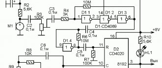
Load switch with on-state time limiter (K561TM2, CD4060)
To power many devices, autonomous power supplies are used, the energy of which must be saved. In addition, you need to save electricity consumption from the mains, and prevent the useless burning of various light bulbs and the unnecessary operation of other electrical appliances. Here is a diagram...
0 180 1
Timer to turn off power to low current devices
A multimeter is now the most popular radio amateur device, but it also has disadvantages. Autonomous power supply is, of course, an advantage, but it is very easy to forget to turn off the device, and then the rather weak 6F22 battery (analogous to the Krona) can quickly be used up. The best way to avoid...
0 116 0
Digital Laboratory Stopwatch 0.01-99 Seconds (CD4060, 74C926)
Scheme of a homemade digital stopwatch that allows you to measure time intervals from 0.01 seconds to 99.99 seconds. The device is based on the MM74S926 microcircuit (or other analogs of “74S926”, which is a four-digit decimal counter combined with an indication system...
1 724 1
Automatic for cyclic zeroing or power interruption (CD4060)
This circuit is designed to cyclically reset or interrupt power to any device that requires such action. Assembled on a CD4060 chip. The interruption (zeroing) period depends on the setting of resistor R1 and can be from one to 4-5 hours...
0 788 0
A simple timer for controlling a 220V load (CD4060)
This timer is designed to limit the operating time of an electrical appliance. The time can be set from 5 minutes to 90 minutes. The time is set using an RC circuit with a variable resistor, so the accuracy is not calibrated. A special feature of the timer is its complete disconnection from the mains...
0 1029 0
Electronic relay for temporary switching of low voltage loads
This device is a time relay that turns on a low-voltage load when a button is pressed, and turns it off 1-10 minutes (the time is set using a variable resistor) after the button is released. The diagram is shown in the figure. Duration of load on state...
1 443 0
Cyclic timer, every 60 minutes turns on the load for 5 minutes
A diagram of a simple homemade device that turns on the load for 5 minutes every 60 minutes. The application of this device can be very different, for example, controlling a borehole pump or another device that needs to be turned on for a short time every hour, for example...
1 893 0
Timer for daily load switching (CD4060B, CD4001)
There are things that need to be done every day at approximately the same time. For example, turn on the light in the yard in the evening and turn it off in the morning, or water the flowers, feed the fish. This timer is designed to perform work for a person such as turning on and off the load once a day...
1 988 1
Universal binary timer using CD4060B chips and diodes
This unusual timer allows you to turn on the load after a time specified with an accuracy of a second, from 1 second to more than 97 days. The unusual thing about the timer is that it is difficult to handle, and the need for some mathematical calculations to set the time (it is advisable to have it as an appendix...
0 556 0
Timer to limit operating time of 12-volt equipment
The figure shows a circuit diagram of an automatic machine for limiting the operating time of equipment. powered by a DC source with a nominal voltage of 12V. Limiter operation. The limiter is powered parallel to the load. To turn on, use a soft button. To turn on the load, you need to press this...
1 626 0
1 …


