What are schemes?
Connecting the windings with a star is their connection at one point, which is called the zero point or neutral.
It is designated by the letter "O". A delta connection diagram is a series connection of the ends of the working windings, in which the beginning of one winding is connected to the end of another.
The difference is obvious. But what is the purpose of these types of connections, why are star-delta connections used in different electrical installations, what is the effectiveness of both. Many questions arise on this topic, and we need to sort them out.
Let's start with the fact that when starting the same electric motor, the current, which is called starting, has a high value, which exceeds its rated value by six or eight times. If it is a low-power unit, then the protection can withstand such a current, but if it is a high-power electric motor, then no protective blocks will withstand it. And this will certainly cause a voltage “sag” and failure of fuses or circuit breakers. The engine itself will begin to rotate at a low speed, different from the nameplate speed. That is, there are many problems with starting current.
Therefore, it just needs to be reduced. There are several ways to do this:
- install one of the following devices in the electric motor connection system: transformer, inductor, rheostat;
- the connection diagram of the rotor windings changes.
It is the second option that is used in production as the simplest and most effective. The star-delta circuit is simply converted. That is, when starting the engine, its windings are connected in a star pattern, then as soon as the motor picks up speed, it switches to a triangle. The process of switching star to delta is done automatically.
It is recommended that in electric motors where two connection options are used simultaneously - star-delta - to connect the windings according to the star circuit, that is, to their common connection point, connect the neutral from the power supply. Why is this necessary? The thing is that when working with this connection option, there is a high probability of asymmetry in the amplitudes of different phases. It is the neutral that will compensate for this asymmetry, which usually appears due to the fact that the stator windings may have different inductive reactance.
Connection of the generator windings and receiver phases with a triangle
The connection of the generator windings or receiver phases, in which the beginning of one phase is connected to the end of the other, forming a closed circuit, is called a delta connection
m (Δ).
The beginning of phase A
of the power supply is connected to the end of phase
B
(
Y
)
and the connection point is designated
A. Next, connect points B
and
Z
(point
B
) and points
C
and
X
(point
C
). The positive directions of the EMF in the windings are the same as when connecting the generator windings in a star.
The phases of the receiver are connected in a similar way, the resistance of which is designated by two indices corresponding to the beginning and end of the phase. Phase currents flow through the phases of the receiver, and. The conditional positive direction of the phase currents of the receiver is taken from the point of the first index to the point of the second index. Conditional positive direction of phase voltages, and coincide with the positive direction of phase currents. The conditional positive direction of linear currents is taken from the power source to the receiver.
When the source is turned off, when the currents , and are equal to zero, in the closed circuit of the power source windings the current is zero, since the EMF system is symmetrical and the total EMF in the circuit is zero (). If the connection of the windings with a triangle is made incorrectly, that is, the ends or beginnings of two phases are connected at one point, then the total EMF in the triangle circuit is different from zero and a large current flows through the windings. This is an emergency mode for the power supply and is therefore not allowed.
The voltage between the start and end of a phase in a delta connection is the voltage between the line wires. Therefore, in a delta connection, the line voltage is equal to the phase voltage:
.
When a receiver connected by a delta is connected to a power source, a phase current flows through the phases of the receiver, which is determined by Ohm’s law:
,
where is the complex impedance of the receiver phase.
For example, , where ; .
Linear currents can be determined from equations written according to Kirchhoff's first law: for point A'
;
for point B'
;
for point C'
.
Thus we get:
.
So, the linear currents when connected by a triangle are equal to the vector difference of the phase currents of those phases that are connected by a given linear wire.
As follows from the previous equations, the vector sum of linear currents is always zero:
.
The system of linear (phase) voltages, and when connected by a triangle, forms the same closed triangle as when connected by a star. Phase currents, and with a symmetrical load, are equal in value and shifted relative to the voltage vectors by the same angle φ
.
To determine the linear currents, a vector diagram of the same phase currents as in the previous figure is constructed in the figure.
Since linear currents are determined through phase ones in the same way as linear voltages through phase ones when connected by a star, it is possible to immediately construct linear current vectors by connecting the ends of the phase current vectors. Linear current vectors form a closed triangle. Since with a symmetrical load the systems of phase and linear currents are symmetrical, comparing the vector diagrams of currents and voltages, we can conclude that the linear currents with a symmetrical load connected in a triangle are several times greater than the phase ones:
.
In the general case, when the load is asymmetrical, the systems of phase and linear currents are also asymmetrical (Figure b
).
The receiver phase connection diagram (star or triangle) does not depend on the power source winding connection diagram. The electrical receiver is connected to a power source having three or four terminals. With three clamps ( A
,
B
and
C
) the windings of the power source can be connected either as a star without a neutral point, or as a triangle.
With four terminals ( A
,
B
,
C
and
N
), the windings of the power source are connected in a star with the neutral point brought out. The receiver phases can only be connected in a star to the neutral wire in this case.
Connection of electric motor windings with triangle and star
Today, high-power asynchronous electric motors are distinguished by reliable operation and high performance, ease of operation and maintenance, as well as reasonable prices. The design of this type of engine allows it to withstand strong mechanical overloads.
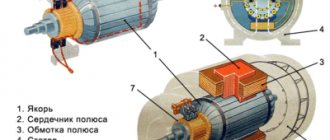
As is known from the basics of electrical engineering, the main parts of any engine are a static stator and a rotor rotating inside it.
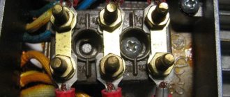
Both of these elements consist of conductive windings, while the stator winding is located in the grooves of the magnetic core maintaining a distance of 120 degrees. The beginning and end of each winding are brought out into an electrical distribution box and installed in two rows.
When voltage is applied from a three-phase power supply to the stator windings, a magnetic field is created. This is what makes the rotor rotate.
An experienced electrician knows how to connect an electric motor correctly.
The connection of an asynchronous motor to the electrical network is carried out only according to the following schemes: “star”, “triangle” and their combinations.
Connection of generator windings with a triangle
| • Three-phase circuits • |
- Three-phase systems
- Star connection of generator windings
- Connection of generator windings with a triangle
- Connecting energy receivers with a star
- Connecting energy receivers in a triangle
- Asymmetrical mode of three-phase circuits
- …
| • Site overview • |
- Electrical equipment up to 1000 V
- Electrical apparatus
- Electric cars
- Operation of electrical equipment
- Electrical equipment of electrical technological installations
- Electrical equipment for general industrial installations
- Electrical equipment for lifting and transport installations
- Electrical equipment of metalworking machines
- Electrical equipment above 1000 V
- High voltage electrical apparatus
- Electrical engineering
- Electric field
- DC electrical circuits
- Electromagnetism
- DC Electrical Machines
- Basic concepts related to alternating currents
- AC circuits
- Three-phase circuits
- Electrical measurements and instruments
- Transformers
- AC Electrical Machines
- Electrical installation
- Where does electrical installation of power supply of electrical equipment and wiring begin?
- Electrical wiring installation
- Calculation of power consumption, cable cross-section and circuit breaker rating
- Electrical installation work and cable laying in residential and non-residential premises
- Electrical installation work on disconnecting junction boxes and electrical equipment
- Electrical installation and grounding of sockets
- Electrical installation of potential equalization
- Electrical installation of the ground loop
- Electrical installation of a modular pin ground loop
- Electrical installation of heating cable for underfloor heating
- Electrical installation work on laying cables in the ground
- Electricity in a private house
- Power supply project
| • Electrical engineering • |
- Electric field
- DC electrical circuits
- Electromagnetism
- DC Electrical Machines
- Basic concepts related to alternating currents
- AC circuits
- Three-phase circuits
- Electrical measurements and instruments
- Transformers
- AC Electrical Machines
- …
ELECTROSPETS
ELECTROSPETS
When connecting the windings of a three-phase generator in a triangle (Fig. 7-8), the end of the first winding X is connected to the beginning of the second winding B, the end of the second winding Y is connected to the beginning of the third winding C, and the end of the third winding Z is connected to the beginning of the first A. Three linear wires going to energy receivers are connected to the beginnings of phases A, B and C.
From Fig. 7-8 it is clear that with such a connection of the windings, the phase voltages are equal to the linear ones, i.e.
When connected in a delta, the three phases of the generator form a closed circuit with very low resistance. Obviously, such a connection is possible only if the sum of e. d.s acting in this circuit will be equal to zero, since otherwise a significant current will arise in the circuit, even in the absence of load, which can cause overheating of the generator. The sum of three symmetrical e . d.s acting in the generator windings is zero . This can be easily verified by adding the vectors e. d.s. In Fig. 7-9 three vectors e are given. d.s. Adding EA and EB, we obtain a vector equal and opposite to the vector EC, i.e.
and therefore the sum of three vectors e. d.s. is equal to zero, i.e.
Incorrect triangle connection of the generator windings is dangerous.
In Fig. 7-10 shows one of the possible incorrect connection schemes, in which the end of the first phase X is correctly connected to the beginning of the second phase B, but the end of the second phase Y is connected not to the beginning of the third phase C, but to its end Z, and the beginning of the third phase C is connected with the beginning of the first phase A, as a result of which e. d.s. EC does not stack with other e. d. s, and is deducted from their amount. The resulting e. d.s. can be determined from the vector diagram in Fig. 7-11 , on which the addition of vectors EA, EB and - EC was performed. The sum of these three vectors, as can be seen from the diagram, is equal to twice the EC vector, i.e.
So in this case e. d.s. of a closed circuit in absolute value is equal to twice the value of the phase e. d.s., which with low resistance of the circuit (generator windings) is equivalent to a short circuit.
Star motor connection
The most commonly used is the star connection, because in this mode the necessary power is provided and good torque on the shaft is guaranteed. But it is worth understanding that an underloaded motor in a 3-phase network will consume excess power, so it is better to use a less powerful motor or adjust the frequency of the supply transformer or drive, depending on the voltage source.
And to determine the electrical parameters of the network, it is necessary to use the relation √3. Initially, it should be noted that when connected in a star, the linear and phase currents are the same, and the voltage is determined by the formula U = √3 × U f. It is not difficult to find the phase voltage from it. Accordingly, powers are determined taking into account this ratio:
S = √3 × U × I
It should be remembered that if the transformer, in addition to 3 phases, also has a 4th terminal from the middle point, then it must be connected to the electric motor.
Star phase connection
The figure shows a star connection diagram of the generator phases.
The symbol for this scheme is Y. The ends K of all three phases are connected to a common point called zero. If only three wires are taken from the generator A, B, C, then such a system is called a three-phase three-wire system. If the fourth, neutral, or “zero” wire N (O) is also removed, then the system is called three-phase four-wire. The zero point of the generator, and therefore the neutral wire, is reliably grounded. Current in the neutral wire will appear only when the three phases are unevenly loaded. The current flowing through the neutral wire is equal to the algebraic sum of the currents in three phases:
In absolute value, in is always less than the current in any of the phases if the load is included in all phases. Therefore, the cross-section of the neutral wire is taken to be smaller than the cross-section of the phase wires.
Rice. 1. Scheme of connecting the generator windings in a star.
Only if the load is connected between one of the phases and the neutral wire, and the load is not connected to the other phases, the current in the loaded phase is equal to the current in the neutral wire.
The voltage between any of the phases and the neutral wire is called phase voltage and is designated U f. It is equal to the voltage between the beginning of each phase and its end (Fig. 2).
The voltage between phase wires is called line voltage and is designated U l. It is equal to the geometric difference between two phase voltages (Fig. 2), that is, linear voltages between phases A and B, B and C, C and A
Rice. 2. Vectors of linear and phase voltages.
The absolute value of the line voltage can be determined from the triangle of vectors AOB. The base of this triangle AB is equal to the linear voltage:
Thus, in a three-phase four-wire system, two voltages are obtained: U f - phase and U l - linear. Line voltage is 1.73 times greater than phase voltage. The current strength in the linear wire I l is equal to the magnitude and direction of the current in the phase winding I f.
The following voltages are accepted for low-voltage networks (Table 1).
Table 1 Standard voltages in consumer networks
As can be seen from Table 1, the voltage of the power supply source (generator or secondary side of the transformer) is always taken at 5% more than the rated mains voltage, taking into account the fact that about 5% of the voltage will be lost in the line. This is done in order to supply consumers with rated voltage electricity and ensure their satisfactory operation.
In agriculture, the most widely used three-phase four-wire system is 380/220 V, that is, a system with a linear voltage in the network Ul = 380 V and phase Uph = 220 V. Three phases with a voltage between them of 380 V are used to power electric motors and three-phase heating devices , and the voltage between phase and neutral wire 220 V is used to power light sources and household electrical appliances.
Source
Basic formulas
Before you get acquainted with the features of how to connect a star-delta electric motor, it is worth remembering the basic formulas for calculating power and the ratio of voltages and currents between them. When calculating devices powered by an alternating voltage network or a separate transformer, the concept of total power is used. It is denoted by the capital letter S and is found as the product of the effective value of voltage and current U × I. Also, it is possible to calculate based on the EMF, at which S = E × I.
In addition to the full one, there are also:
- active;
- reactive power.
In the first case, it is denoted by the letter P = E × I × cos φ or P = U × I × cos φ. In the second case, Q = E × I × sin φ or Q = U × I × sin φ. Where in the formulas E is the electromotive force, I is the current, φ is the angle between the voltage and current created by the phase shift in the windings.
If the motor windings are identical to each other in all respects, then all types of power are determined as the product of current and voltage multiplied by 3.
Properties of star and triangle
Publication date: July 17, 2013. Category: Articles.
Typical cases of star and delta connections of generators, transformers and power receivers are discussed in the articles “Star connection diagram” and “Triangle connection diagram”. Let us now dwell on the most important issue of power it is power that is ultimately important .
In AC networks they distinguish: total (apparent) power S = E × I or S = U × I; active power P = E × I × cos φ or P = U × I × cos φ; reactive power Q = E × I × sin φ or Q = U × I × sin φ, where E is the electromotive force (emf); U – voltage at the terminals of the electrical receiver; I – current; φ – phase shift angle between current and voltage 1.
Engine design
The windings are located on the stator, and the rotor is short-circuited in the form of a squirrel wheel: aluminum or copper rings at the ends are connected to each other by parallel jumpers. The stator is wound in a special way with a certain number of poles, which depends on the power parameters and the supply network. Household fans have only 2 poles, industrial traction motors have 8 or more.
The advantages of using asynchronous electric motors with a star or delta connection circuit are obvious and are as follows:
- Increased endurance - even at loads exceeding the rated load, the engine will operate without failure.
- Ability to work in aggressive environments. Due to the absence of sliding contacts, sparking cannot occur in the engine, and, consequently, problems associated with it. With high-quality insulation, the electric motor can operate in damp environments.
- Long operating time at high loads. The engine is capable of operating for a long period of time under significant load on the shaft without overheating and burning out the windings.
Beginners, and not only others, will find this article about the parameters, pinout and analogues of the KT815 transistor useful.
How to choose capacitors: 3 important criteria
A three-phase motor creates a rotating magnetic field of the stator due to the uniform passage of sinusoidal currents through each winding, spaced apart in space by 120 degrees.
There is no such possibility in a single-phase network. If you connect one voltage to all 3 windings at once, there will be no rotation - the magnetic fields will balance. Therefore, voltage is applied to one part of the circuit as it is, and the current is shifted to the other according to the angle of rotation by capacitors.
The addition of two magnetic fields creates an impulse of moments that spin the rotor.
The performance of the created circuit depends on the characteristics of the capacitors (capacitance value and permissible voltage).
For low-power engines with easy starting at idle, in some cases it is permissible to use only working capacitors. All other engines will require a starting block.
I draw attention to three important parameters:
- capacity;
- permissible operating voltage;
- type of construction.
How to choose capacitors by capacitance and voltage
There are empirical formulas that allow you to perform a simple calculation based on the rated current and voltage.
However, people often get confused about the formulas. Therefore, when checking the calculation, I recommend taking into account that for a power of 1 kilowatt it is necessary to select a capacitance of 70 microfarads for the operating circuit. The dependence is linear. Feel free to use it.
All these methods can and should be trusted, but theoretical calculations must be tested in practice. The specific design of the engine and the loads applied to it always require adjustments.
Capacitors are designed for the maximum current value allowed under the heating conditions of the wire. This consumes a lot of electricity.
If the electric motor overcomes loads of smaller magnitude, then it is advisable to reduce the capacitance of the capacitors. This is done experimentally during setup, measuring and comparing the currents in each phase with an ammeter.
Most often, metal-paper capacitors are used to start an asynchronous electric motor.
They work well but have low ratings. When assembled into a capacitor bank, the result is a rather large design, which is not always convenient even for a stationary machine.
Nowadays the industry produces small-sized electrolytic capacitors adapted for operation with alternating current electric motors.
Their internal structure of insulating materials is adapted to work under different voltages. For a working chain it is at least 450 volts.
For a starting circuit with conditions of short-term switching on under load, it is reduced to 330 due to a decrease in the thickness of the dielectric layer. These capacitors are smaller in size.
This important condition must be well understood and put into practice. Otherwise, 330 volt capacitors will explode during prolonged operation
Most likely, for a particular engine, you won’t be able to get rid of it with just a capacitor. You will need to assemble the battery using a series and parallel connection of them.
When connected in parallel, the total capacitance is summed, but the voltage does not change.
Connecting capacitors in series reduces the total capacitance and divides the applied voltage between them.
What types of capacitors can be used
The rated voltage of the network is 220 volts - this is the effective value. Its amplitude value is 310 volts. Therefore, the minimum limit for short-term operation at startup is 330 V.
A voltage reserve of up to 450 V for working capacitors takes into account surges and impulses that are created in the network. It cannot be underestimated, and the use of capacities with a large reserve significantly increases the dimensions of the battery, which is irrational.
For a phase-shifting chain, it is permissible to use polar electrolytic capacitors, which are designed to allow current to flow in only one direction. Their connection circuit must contain a current-limiting resistor of several ohms.
Without its use, they quickly fail.
Before installing any capacitor, you should check its actual capacity with a multimeter, and not rely on the factory markings. This is especially true for electrolytes: they often dry out prematurely.
How to control motor switching
Often, to start a high-power electric motor, switching the delta connection to a star connection is used; this is necessary to reduce the current parameters at start-up. In other words, the engine starts in star mode, and all work is carried out on a delta connection. For this purpose, a three-phase contactor is used.
When automatically switching, the following prerequisites must be met:
- block contacts from simultaneous activation;
- mandatory performance of work, with a time delay.
A time delay is necessary for 100% disconnection of the star connection, otherwise, when the delta connection is turned on, a short circuit will occur between the phases. A time relay (RT) is used, which delays the switching by an interval of 50 to 100 milliseconds.
How can you delay switching times?
When a “star-delta” circuit is used, it is imperative to delay the connection turn-on time (Δ) until the connection (Y) is turned off; experts prefer three methods:
- using a normally open contact in the time relay, which blocks the delta circuit when the electric motor starts, and the switching moment is controlled by the current relay (RT);
- using a timer in a modern time relay, which has the ability to switch modes with an interval of 6 to 10 seconds.
Standard switching scheme
The classic option of switching from star to delta is considered by experts to be a reliable method, it does not require large expenses, is easy to implement, but, like any other method, it has a drawback - the overall dimensions of the time relay. This type of RF is guaranteed to perform a time delay by magnetizing the core, and it takes time to demagnetize it.
The mixed (combined) switching circuit works as follows. When the operator turns on the three-phase circuit breaker (AB), the motor starter is ready for action. Through the contacts of the “Stop” button, the normally closed position and through the normally open contacts of the “Start” button, which is pressed by the operator, electric current passes into the contactor coil (CM). Contacts (BKM) provide self-picking of power contacts and keep them in the on position.
The relay in the circuit (KM) provides the ability for the operator to turn off the electric motor with the “Stop” button. When the “control phase” passes through the start button, it also passes through the closed normally located contacts (BKM1) and contacts (RV) - the contactor (KM2) starts, its power contacts supply voltage to the connection (Y), and the rotation of the electric motor rotor begins.
When the operator starts the engine, the contacts (BKM2) in the contactor (KM2) open, this creates an inoperative state of the power contacts (KM1), which provide power to the motor connection Δ.
The current relay (RT) operates almost immediately due to high current values, which are included in the circuit of current transformers (CT1) and (CT2). The control circuit of the contactor coil (KM2) is shunted by the contacts of the current relay (RT), which prevents the (RV) from operating.
In the contactor circuit (KM1), the contact block (BKM2) opens when starting (KM2), which prevents the coil (KM1) from operating.
With the set of the desired motor rotor speed parameter, the contacts of the current relay open, since the starting current decreases in the control of the contactor (KM2), simultaneously with the opening of the contacts supplying voltage to the winding connection (Y), BKM2 are connected, which brings the contactor (KM1) into the operating position ), and in its circuit the block of contacts BKM2 opens, and, as a result, the RV is de-energized. The transformation of the "triangle" into a "star" occurs after the engine is stopped.
Important! The temporary relay does not turn off immediately, but with a delay, which allows the relay contacts in the circuit (KM1) to be closed for some time, this ensures the start (KM1) and operation of the engine in a “triangle” pattern
Disadvantages of the standard scheme
Despite the reliability of the classical circuit for switching from one connection to another connection of a high-power electric motor, it has its disadvantages:
it is necessary to correctly calculate the load on the electric motor shaft, otherwise it will take a long time to gain speed, which will not allow the current relay to quickly operate and then switch to operation via the Δ connection, and it is also extremely undesirable to operate the motor for a long time in this mode;
Practice - how to choose a scheme for a specific case
Most often, electricians work with a 380/220V network, so let’s look at how to connect an electric motor, star or delta, to such a three-phase electrical network.
In most electric motors, the winding connection diagram can be changed; for this purpose, there are six terminals in the Brno, they are located in such a way that with the help of a minimum set of jumpers you can assemble the circuit you need. In simple words: the terminal of the beginning of the first winding is located above the end of the third, the beginning of the second, above the end of the first, the beginning of the third above the end of the second.
You can see how to distinguish the two options for connecting an electric motor in the figure below.
Let's talk about which scheme to choose. The connection diagram of the electric motor coils does not have a particular influence on the operating mode of the engine, provided that the nominal parameters of the engine comply with the supply network. To do this, look at the nameplate and determine what voltages your particular electrical machine is designed for.
Typically the marking looks like:
Δ/Y 220/380
It deciphers like this:
If the phase-to-phase voltage is 220, assemble the windings in a triangle, and if 380, assemble them in a star.
To simply answer the question “How to connect the windings of a motor?” We have made a connection diagram selection table for you:
Advantages
- Cost-effective when transmitting electricity over long distances, which provides a star-delta connection.
- Low material consumption of three-phase transformers.
- Balance of the system. This point is one of the most important, since it allows you to avoid uneven mechanical load on the power generating installation. This results in a longer service life.
- Power cables have low material consumption. Thanks to this, with the same power consumption, the currents required to maintain a star-delta connection are reduced compared to single-phase circuits.
- It is possible, without significant effort, to obtain a circular rotating magnetic field, which is necessary for the operation of an electric motor and a number of other electrical devices that operate on a similar principle. This is achieved due to the possibility of creating a simpler and at the same time effective design, which, in turn, follows from the efficiency indicators. This is another significant advantage that the star and delta connection has.
- In one installation you can obtain two operating voltages - phase and linear. It is also possible to make two power levels when there is a delta or star connection.
- You can dramatically reduce the flickering and stroboscopic effect of lamps operating on fluorescent lamps by following the path of placing devices powered from different phases in it.
Thanks to the above seven advantages, three-phase systems are now the most common in modern electronics. The star/delta connection of the transformer windings allows you to select the optimal options for each specific case. In addition, the ability to influence the voltage transmitted through networks to residents’ homes is invaluable.
Three-phase star connection
A three-phase power supply system is a special case of multiphase electrical circuit systems in which sinusoidal EMFs of the same frequency created by a common source operate, shifted relative to each other in time by a certain phase angle. In a three-phase system, this angle is 2π/3 (120°).
The multi-wire (six-wire) three-phase alternating current system was invented by Nikola Tesla. A significant contribution to the development of three-phase systems was made by M. O. Dolivo-Dobrovolsky, who was the first to propose three- and four-wire alternating current transmission systems, identified a number of advantages of low-wire three-phase systems in relation to other systems, and conducted a number of experiments with an asynchronous electric motor.
Each of the operating EMF is in its own phase of the periodic process, therefore it is often called simply “phase”. Also called “phases” are conductors - carriers of these EMFs. In three-phase systems, the shear angle is 120 degrees. Phase conductors are designated in the Russian Federation by the Latin letters L with a digital index 1...3, or A, B and C.
Advantages. Economical.
Cost-effective transmission of electricity over long distances.
Less material consumption of 3-phase transformers.
Less material consumption of power cables, since with the same power consumption the currents in the phases are reduced (compared to single-phase circuits).
Balance of the system. This property is one of the most important, since in an unbalanced system an uneven mechanical load occurs on the power generating installation, which significantly reduces its service life.
The ability to easily obtain a circular rotating magnetic field necessary for the operation of an electric motor and a number of other electrical devices. 3-phase motors (asynchronous and synchronous) are simpler in design than single- or 2-phase DC motors and have high efficiency indicators.
The ability to obtain two operating voltages in one installation - phase and linear, and two power levels when connected to a star or delta.
The ability to sharply reduce the flickering and stroboscopic effect of lamps using fluorescent lamps by placing three lamps (or groups of lamps) powered from different phases in one lamp.
Thanks to these advantages, three-phase systems are the most common in modern power generation.
A star connection is such a connection when the ends of the phases of the generator windings (G) are connected to one common point, called the neutral point or neutral. The ends of the phases of the consumer windings (M) are also connected to a common point. The wires connecting the beginning of the generator and consumer phases are called linear. The wire connecting two neutrals is called neutral.
Tires for distributing neutral wires (blue) and ground wires (green).
A three-phase circuit with a neutral wire is called a four-wire circuit. If there is no neutral wire, a three-wire one.
The difference in connecting the electric motor according to the indicated schemes is the connection of the ends of the windings. In a star circuit, all the ends of the windings are connected together, and in a delta circuit, the end of one winding begins with the beginning of the next. When connecting according to the first circuit (“star”), power is supplied to the beginning of the stator windings, and with the second, to the places where different windings are connected to each other. When connecting in a star, it is recommended to connect the neutral of the power source to the connection point of all ends of the windings. This is done to compensate for possible asymmetry in the amplitude of the various supply phases, which may be due to the different inductive reactance of each winding.
If the resistances Za, Zb, Zc of the consumer are equal to each other, then such a load is called symmetrical.
The voltage between the line wire and the neutral (Ua, Ub, Uc) is called phase. The voltage between two line wires (UAB, UBC, UCA) is called line voltage. To connect windings with a star, with a symmetrical load, the relationship between linear and phase currents and voltages is valid: Ul = 2Uф cos 30°, Il = IФ
Star and delta connection of windings
In this case, if the current relay is excluded from the circuit, and mode switching is carried out according to the timer setting, then at the moment of transition to the triangle, the same current surges will be observed of almost the same duration as when starting from a stationary rotor state.
The beginning of the terminals is connected to the corresponding phases of the supply network. For these purposes, when operating an asynchronous electric motor, special manual control electrical devices are used, which include reversing switches and batch switches or more modernized remote control devices - reversing electromagnetic starters and switches. To compensate for the losses, you have to find a high-capacity μF capacitor with an operating voltage of at least V.
If it is a low-power unit, then the protection can withstand such a current, but if it is a high-power electric motor, then no protective blocks will withstand it.
There is no neutral wire in it, there is simply nowhere to connect it. With such wiring, you should be guided solely by the information indicated on the technical plate. It is not possible to configure such engines in any other way, in everyday conditions. However, simplicity requires sacrifice.
Read additionally: Who should do the energy passport of an enterprise?
Star connection and its advantages
When three-phase voltage appears in the windings, magnetic fluxes are formed at their poles. In general, he connected it incorrectly, which is why the engine burned out
It is also worth paying attention to the fact that the starting-protective equipment is selected for the rated power of the electric motor, but if the star connection is incorrect, it simply physically cannot perform its functions
Soft start of the engine. For alternating current networks of 50 Hz, the linear voltage is higher than the phase voltage by the square root of three times, that is, approximately 1. When quoting site materials, there is an active hyperlink to l With such a decrease in voltage, the incandescence of the lamps decreases, the torque of other electric motors decreases, and the contactors spontaneously turn off. Star and triangle connection principle.
Star connection
Let's consider the star connection diagram of the generator windings . In it, the ends of three windings are connected into one node, and the beginnings are used to connect loads.
The star connection diagram is shown in Fig. 1 (a). This connection of the generator windings allows you to use only four wires instead of six to transmit electricity. Point $O$ in the diagram is a point of common potential (the conductor that is connected to point $O$ is the neutral wire). Such a connection is similar to the connection of three current sources, which is shown in Fig. 1 (b).
Finished works on a similar topic
- Course work Connection of generator windings with “star” and “triangle” 480 rub.
- Abstract Connection of generator windings “star” and “delta” 260 rub.
- Test work: Star and delta connection of generator windings 220 RUR.
Receive completed work or specialist advice on your educational project Find out the cost
Picture 1.
With this connection method, the voltage between the phase and the neutral wire is called phase voltage. The voltage between phases $AB$, $BC$, $CA$ is called linear . In order to determine how phase and line voltages relate, it is necessary to take the geometric (vector) difference.
Let's assume that the generator is open, that is, $R_1=\R_2=R_3=\infty ,\ $we will find the connection between the phase voltage (existing in each of the windings $O_1,\O_2,O_3$) and linear voltages (between the wires $0,1 ,2,3$). The line voltage between wire $O$ and any other wire is equal to the phase voltage and its amplitude is $U_m.\ $The line voltage between any pair of wires $1,2$ and $3$ will be different. Let us find the voltage between wires $1$ and $3$, which is equal to the potential difference between the free ends of the windings $O_1,\ O_2$:
Have questions about this topic? Ask a question to the teacher and get an answer in 15 minutes! Ask a Question
From formula (2) it is clear that the linear voltage has the same frequency as the phase voltage. However, the amplitude of the linear voltage is $\sqrt{3}$ greater than that of the phase voltage.
Let's assume that the generator has a symmetrical load ($R_1=\R_2=R_3$). In this case, the amplitude of the currents in wires $1,2,3$ is the same ($I_m$). The current strength will change according to:
In the neutral wire, the current ($I$) is equal to the sum of the line currents:
Because:
${sin \left(\omega t-120{}^\circ \right)\ }+{sin \left(\omega t-240{}^\circ \right)\ }=2{sin \left(\ omega t-180{}^\circ \right)\ }cos60{}^\circ ={sin \left(\omega t-180{}^\circ \right)\ }$=-${sin \left( \omega t\right)\ }.$
We found that with a symmetrical load, the current in the neutral wire is always zero. In this case (with a symmetrical load!) the neutral wire can be removed completely and the line will work (however, we must remember that in this case, each pair of loads will be affected by a line voltage $\sqrt{3}$ times greater than the phase voltage).
Star connection and its advantages
Each of the three working windings of the electric motor has two terminals - the beginning and the end, respectively. The ends of all three windings are connected to one common point, the so-called neutral.
If there is a neutral wire in the circuit, the circuit is called 4-wire, otherwise, it will be considered 3-wire.
The beginning of the terminals is connected to the corresponding phases of the supply network. The applied voltage on such phases is 380 V, less often 660 V.
The main advantages of using the star scheme:
- Stable and long-term non-stop operation of the engine;
- Increased reliability and durability by reducing equipment power;
- Maximum smooth start-up of the electric drive;
- Possibility of exposure to short-term overload;
- During operation, the equipment housing does not overheat.
There is equipment with internal connection of the ends of the windings. Only three pins will be output to the block of such equipment, which does not allow the use of other connection methods. Electrical equipment made in this form does not require competent specialists for its connection.
Connecting a three-phase motor to a single-phase network using a star circuit
Triangle connection and its advantages
The principle of the “triangle” connection is to connect in series the end of the winding of phase A with the beginning of the winding of phase B. And then, by analogy, the end of one winding with the beginning of another. As a result, the end of the phase C winding closes the electrical circuit, creating an unbroken circuit. This scheme could be called a circle, if not for the mounting structure. The triangle shape is given by the ergonomic placement of the winding connection.
When connected by a “triangle” on each of the windings, there is a linear voltage equal to 220V or 380V.
The main advantages of using the triangle scheme:
Flaws:
The “triangle” method of connecting motor windings is widely used when working with powerful mechanisms and the presence of high starting loads. A large torque is created due to an increase in the self-induction EMF caused by large flowing currents.
Connecting a three-phase motor to a single-phase network using a triangle diagram
Mechanism design
An asynchronous motor is divided into two groups, which depend on the method of rotor winding:
- Motors with phase winding. They have a complex rotor design, which makes the production of the device significantly more expensive than other types of engines. They are used in difficult starting conditions and when smooth adjustment of the rotation speed is necessary.
- Motors with squirrel-cage windings. The device has a lower manufacturing cost and its rotation speed changes by only 2-3 percent when the load changes from 0 to the minimum frequency. The only drawback is the difficulty of smoothly adjusting the rotation speed over large limits.
The device consists of a stationary cylinder - a stator, which consists of sheets of electrical steel, insulated from each other with technical varnish and assembled using brackets to reduce eddy currents. In the stator slots there is a stator winding connected in a triangle or star combination. The device also consists of a rotating part - a rotor assembled from sheets of electrical steel, where aluminum or copper is poured into the grooves under pressure. The closing rings on which the blades are located are also poured together. They are necessary to cool the rotor.
The rotor is fixed to the motor shaft, on which the bearings are fixed. This entire structure is located in bearing shields.
Operating principle of an asynchronous motor
If voltage is applied to the stator winding, an alternating sinusoidal current begins to flow through it, creating a magnetic field. It crosses the rotor winding, in which an alternating electromotive force is induced. The EMF produces an alternating current in the rotor winding, and this current creates a rotating magnetic field of the rotor.
The stator and rotor fields are connected and form a common rotating magnetic field of the motor, which interacts with the current in the rotor winding and generates force according to the left-hand rule. It turns the rotor in the direction of rotation of the magnetic field.
The device is called asynchronous due to the fact that the rotational speed of the magnetic field is several times greater than the rotor speed.
What is the difference
If we talk about connecting single-phase consumers, let’s briefly look at the example of three electric heaters, then in a “star”, if one of them burns out, the remaining two will continue to work. If two out of three burn out, none of them will work at all, since they are connected in pairs to line voltage.
In a triangle circuit, even if 2 heating elements burn out, the third one will continue to work. There is no neutral wire in it, there is simply nowhere to connect it. And in the “star” it is connected to the neutral point, and it is needed to equalize the phase currents and their symmetry in the case of different loads across the phases (for example, in one of the branches there is 1 heating element connected, and in the rest there are 2 in parallel).
But if with such a connection (with different loads in phases) the zero burns out, then the voltages will be unequal (where the load is greater, it will sag, and where it is less, it will increase). We wrote more about this in the article on phase imbalance.
It should be taken into account that it is impossible to connect ordinary single-phase devices (220V) between phases at 380V. Either the devices must be designed for such power, or the network must be with Ulinear 220V (as in electrical networks with an isolated neutral of some specific objects, for example, ships).
But, when connecting a three-phase motor, zero is often not connected to the midpoint of the star, since this is a symmetrical load.
Selecting a motor phase connection diagram
To connect an asynchronous electric motor to the network, its stator winding must be connected in a star or delta.
To connect an electric motor to a network according to a star circuit, you need to connect all the ends of the phases (C4, C5, C6) electrically to one point, and connect all the beginnings of the phases (C1, C2, C3) to the phases of the network. The correct connection of the ends of the phases of the electric motor according to the “star” scheme is shown in Fig. 1, a.
To turn on the electric motor according to the “triangle” scheme, the beginning of the first phase is connected to the second phase, the beginning of the second to the end of the third, and the beginning of the third to the end of the first. The winding connection points are connected to three phases of the network. The correct connection of the ends of the electric motor phases according to the “triangle” diagram is shown in Fig. 1, b.
Rice. 1. Schemes for connecting a three-phase asynchronous electric motor to the network: a – phases are connected by a star, b – phases are connected by a triangle
Connection of motor phases according to the “star” scheme
Connection of motor phases according to the “triangle” scheme
To select the phase connection diagram of a three-phase asynchronous electric motor, you can use the data in Table 1.
Table 1. Selection of winding connection diagram
| Electric motor voltage, V | Mains voltage, V | |
| 380/220 | 660/380 | |
| 380/220 | star | – |
| 660/380 | triangle | star |
The table shows that when connecting an asynchronous motor with an operating voltage of 380/220 V to a network with a linear voltage of 380 V, its windings can only be connected with a star! It is impossible to connect the ends of the phases of such an electric motor using a “triangle” diagram. Incorrect choice of connection diagram for the electric motor windings can lead to its failure during operation.
The option of connecting the windings with a delta is provided for connecting 660/380 V motors to a network with a linear voltage of 660 V and a phase voltage of 380 V. In this case, the motor windings can be connected according to either a “star” or “delta” circuit.
Such motors can be connected to the network using a star-delta switch (Fig. 2). This technical solution makes it possible to reduce the starting current of a high-power three-phase asynchronous squirrel-cage electric motor. In this case, first the windings of the electric motor are connected in a “star” configuration (with the switch knives in the lower position), then, when the motor rotor reaches the rated speed, its windings are switched to a “delta” configuration (upper position of the switch knives).
Rice. 2. The diagram for connecting a three-phase electric motor using a phase switch from star to delta
The reduction in starting current when switching its windings from star to delta occurs because instead of the delta circuit intended for a given network voltage (660V), each motor winding is switched on at a voltage √3 times less (380V). In this case, the current consumption is reduced by 3 times. The power developed by the electric motor during startup is also reduced by 3 times.
But, in connection with all of the above, such circuit solutions can only be used for motors with a rated voltage of 660/380 V and connected to a network with the same voltage. If you try to turn on an electric motor with a rated voltage of 380/220 V using this scheme, it will fail, because its phases cannot be connected to the network in a “triangle”.
The rated voltage of an electric motor can be viewed on its body, where its technical passport is located in the form of a metal plate.
To change the direction of rotation of the electric motor, it is enough to swap any two phases of the network, regardless of its connection diagram. To change the direction of rotation of an asynchronous electric motor, manual control electrical devices (reversing switches, batch switches) or remote control devices (reversing electromagnetic starters) are used. The diagram for connecting a three-phase asynchronous electric motor to the network with a reversing switch is shown in Fig. 3.
Rice. 3. Scheme for connecting a three-phase electric motor to the network with a reversing switch
§60. Star connection diagram
Scheme "star with neutral wire".
When connecting the phase windings of a three-phase current source (for example, a generator) according to the “star with neutral wire” circuit, the ends of its three windings are connected to a common node 0, which is called the zero point, or source neutral (Fig. 206).
Rice. 206. Scheme “star with neutral wire”, direction of linear and phase currents and voltages in it
Receivers of electrical energy are combined into three groups ZA, ZB and Zc (load phases), the ends of which are also connected into a common node 0′ (zero point, or load neutral). The source windings are connected to the load phases with four wires. Wires 1, 2 and 3 connected to the beginnings of the phase windings (A, B, C) are called linear. Wire 4, connecting the zero points 0 and 0′, is called zero, or neutral.
The voltages uА, uв and uс between the beginnings and ends of the windings of individual source phases or load phases ZA, ZB and Zc are called phase. They are also equal to the voltage between each of the linear wires and the neutral wire. In the absence of voltage loss in the source windings (at no load), the phase voltages are equal to the corresponding e. d.s. in these windings.
Phase currents iA, iB, ic are the currents flowing through the source windings or load phases ZA, ZB and Zc. The voltages uAB, uBC, uCA between linear wires and the currents passing through these wires are called linear.
Let us conventionally assume the positive direction of the currents iA, iB and ic in the source phases - from the end of the corresponding phase to its beginning, in the load phases - from beginning to end, and in linear wires - from the source to the receiver.
We will consider the voltages uA, uB and uC in the source and load phases positive if they are directed from the beginning of the phases to the ends, and the linear voltages uAB, uBC, uCA - if they are directed from the previous phase to the next.
From Fig. 206 it follows that in the “star” circuit the linear currents are equal to the phase currents, i.e. Il = Iph, since there are no branches when transitioning from the source or load phase to the linear wire.
Instantaneous stress values according to Kirchhoff’s second law:
Moving from instantaneous voltage values to their vectors, we have:
Consequently, the linear voltage is equal to the difference between the vectors of the corresponding phase voltages.
Using the obtained vector equations, you can construct a vector diagram (Fig. 207, a), which can be converted into a diagram (Fig. 207, b). From this diagram it is clear that in a symmetrical three-phase system, the linear voltage vectors →uAB, →uBC, →uCA form an equilateral triangle ABC, inside which there is a symmetrical three-ray star of phase voltages →uA, →uB, →uC.
In isosceles triangles AOB, BOC and COA, the base is equal to Ul, the other sides are equal to Uf and the acute angle between these sides and the base is 30°.
Rice. 207. Vector voltage diagrams for the “star with neutral wire” circuit
Thus, in a three-phase system connected according to a “star with a neutral wire” circuit, the linear voltage is √3 times greater than the phase voltage. The value √З = 1.73 is the basis for the scale of nominal AC voltages: 127, 220, 380 and 660 V. In this series, each subsequent voltage value is 1.73 times greater than the previous one.
A current i0 passes through the neutral wire, the instantaneous value of which is equal to the algebraic sum of the instantaneous values of the currents passing in the individual phases: i0 = iA+iB+iC.
Passing from the instantaneous values of currents to their vectors, we have:
Current vectors →iA, →iB and →iC are shifted relative to the corresponding voltage vectors →uA, →uB, →uC by angles →iA, →iB, →iC (Fig. 208, a). The values of these angles depend on the relationship between active and reactance included in a given phase.
The same diagram shows the addition of vectors →iA, →iB and →iC to determine the current vector →i. Usually the current →i is less than the currents
Rice. 208. Vector diagrams of voltages and currents in individual phases for the “star with neutral wire” circuit with uneven (a) and uniform (b) phase loads
IA, 1B and IC are in the line wires, so the neutral wire has a cross-sectional area equal to or even slightly less than the cross-sectional area of the line wires.
In the “star with neutral wire” circuit, electrical energy receivers can be connected to two voltages: linear Ul (when connected to two linear wires) and phase UФ (when connected to the neutral and one of the linear wires).
Star circuit without neutral wire.
With a uniform or symmetrical load of all three phases, when the same active and reactive resistances are included in all phases (RA = RB = RC and XA = XB = XC), the phase currents iA, iB and iC will be equal in magnitude and shifted from the corresponding phase voltages at equal angles. In this case, we obtain a symmetrical system of currents, in which the currents iA, iB, iC will be phase shifted relative to each other by an angle of 120°, and the current i in the neutral wire at any time is zero (Fig. 208, b).
Obviously, with a uniform load, you can remove the neutral wire and transmit the electrical energy of the source to the receiver through three linear wires 1, 2 and 3 (Fig. 209).
Rice. 209. Scheme “star without neutral wire”
This circuit is called a “star without a neutral wire.” With a three-wire system for transmitting electrical energy, at every instant the current flows through one (or two) wires from the three-phase current source to the receiver, and through the other two (or one) it flows back from the receiver to the source (Fig. 210).
Fig. 210. Curves of changes in currents in linear wires (a) with a three-wire system and the direction of currents in them at different times (b c, d)
The vector voltage diagram for the “star without neutral wire” circuit with a uniform phase load will be the same as for the “star with neutral wire” circuit (see Fig. 207).
The relationships between phase and linear currents and voltages will be the same:
It should be noted that the “star without neutral wire” circuit can only be used with a uniform phase load. In practice, this only occurs when connecting electric motors to three-phase current sources, since each three-phase electric motor is equipped with three identical windings that evenly load all three phases.
With an uneven load, the voltages in individual load phases will be different. On some phases (with lower resistance) the voltage will decrease, and on others it will increase compared to normal, which is unacceptable.
An almost uneven phase load occurs when electric lamps are supplied with three-phase current, since in this case the distribution of current between all three phases cannot be guaranteed (individual lamps can be turned on and off individually). Particularly dangerous in a “star without a neutral wire” circuit is a break or short circuit in one of the phases.
It can be shown by constructing the corresponding vector diagrams that if there is a break in one of the phases, the voltage in the other two phases decreases to half the linear one, as a result of which the lamps included in these phases will burn with insufficient power.
If there is a short circuit in one of the phases, the voltage in the other phases increases to linear, i.e. √3 times, and all the lamps turned on in these phases will burn out. Therefore, in the “star with neutral wire” circuit, in order to avoid breaking the neutral wire circuit, fuses and switches are not installed in it.
Source
Differences in connection schemes
Star and delta circuits for electric motors are the only ways to connect them. They differ from each other, providing different operating modes. So, for example, connection using the Y circuit provides smoother operation when compared with motors connected in a “triangle”. This difference plays a key role when choosing the power of an electrical device.
More powerful engines are operated only in delta. The star-delta motor connection diagram is excellent for those cases where it is necessary to ensure a smooth start. And at the right moment, switch between windings to obtain maximum power.
It is important to add here: connection Y guarantees soft operation, but the engine will not be able to reach its rated power. On the other hand, the delta-star-star motor connection circuit will provide more power, but at the same time the value of the starting current for the equipment will also increase significantly
On the other hand, the delta-star-star motor connection circuit will provide more power, but at the same time the starting current for the equipment will also increase significantly.
It is the difference in power between the Y and delta connections that is the main indicator. An electric motor with a star circuit will have a power approximately 1.5 times lower than through a triangle, however, such a connection will help reduce the starting current. All connections that include two connection methods are combined. Usually they are used only in cases where it is necessary to start an electric motor with a large rated power.
The star-delta starting circuit for an electric motor has another advantage. Switching is carried out according to the Y scheme, which reduces the value of the starting current. When the device gains sufficient speed during operation, it switches to a delta circuit to achieve maximum power.