Star connections
When connected by a star, the ends of the phase windings are connected together at one point (in our case shown as x,y,z), which is called the neutral point or zero, and is designated by the letter N. Also, the neutral point (neutral) or zero can be connected to the neutral source, or may not be connected. In the case when the neutrals of the source and receiver of electrical energy are connected, such a system will be called four-wire, and if they are not connected, it will be called three-wire.
Current resonance
In Fig. Figure 3 shows an equivalent circuit of an inductor connected in parallel (taking into account its active resistance) and a capacitor.
Rice. 3. Parallel connection of resistive, inductive and capacitive elements
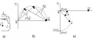
The vector diagram of currents and voltages for this circuit is shown in Fig. 4.
Rice. 4. Vector diagram of currents and voltages for a parallel circuit
The current in the coil circuit Ik can be represented in the form of two components: active Ia, in phase with the voltage U, and reactive IL, lagging behind the voltage by an angle of 90º. The capacitive circuit current Ic is shifted in phase relative to the voltage by also 90º, but in the leading direction.
Consequently, the current Ic is directed counter to the reactive inductance current IL.
By geometrically adding the vectors Ia and IL, we find the coil current Ik, which is shifted relative to the voltage by an angle φk; adding, then, the vector Ik with the vector Ic, we obtain the current I in the unbranched part of the circuit. The current I is generally shifted relative to the voltage by an angle φ.
To practically construct a vector diagram of a parallel circuit, the coil current Ik is measured when the capacitance is turned on, which represents, as mentioned earlier, the geometric sum of the currents Ia and IL.
The phase angle of current Ik and voltage U are determined at C=0 by the formula:
,
Where
— power measured by a wattmeter, W;
— supplied voltage, V;
— inductor current, A.
Current Ic is measured with an ammeter in the capacitance circuit and plotted on the diagram at an angle of 90º in the leading direction.
From the diagram in Fig. 4. It can be seen that connecting the capacitance in parallel with the receiver of electrical energy, which, like most receivers (asynchronous motors, transformers, etc.), has inductance, compensates for the reactive component of the receiver current IL and, therefore, improves the power factor of the circuit.
In the particular case when the capacitive current is equal to the inductive current Ic=IL, current resonance occurs.
In Fig. 5. shows a vector diagram for the case of resonance, from which it can be seen that the geometric sum of reactive currents (Ic and IL) is equal to zero, the current in the unbranched part of the circuit at this moment has the smallest value (equal to the active current Ia) and is in phase with the applied voltage (cosφ=0).
Since IL=UbL
, aIc=Ubc then the condition for current resonance will be the equality of reactive conductivities bL=bc, where bL is the reactive conductivity of the inductance, and bc is the reactive conductivity of the capacitance.
For an equivalent circuit of an inductor and a capacitor connected in parallel (Fig. 3), the reactive conductivities can be determined as follows:
, i.e.
, i.e.
The condition for current resonance for this circuit is the equality
It follows that current resonance, in contrast to voltage resonance, can be obtained by changing any of 4 quantities: L, C, f, R.
Of particular interest is a circuit of two parallel-connected ideal inductive and capacitive elements (Fig. 6).
Rice. 5. Vector diagram for current resonance.
Rice. 6. Parallel connection of ideal inductive and capacitive elements.
Reactive currents of a parallel circuit based on Ohm's law can be expressed in terms of voltage U and the corresponding circuit resistances
,
,
From the formulas it follows that at the moment of resonance, when IL=Ic, the reactive conductivities of the parallel circuits are equal
.
The total current of the circuit is zero (I = 0), although current passes in each of the branches
.
Substituting into the equality of conductivities the value
, we get
.
Consequently, current resonance in an ideal circuit, as well as voltage resonance, can be obtained by changing one of the three quantities L, C and
.
Current resonance, unlike voltage resonance, is a phenomenon that is safe for electrical installations. Moreover, the resonance of currents makes it possible to increase the power factor of the power plant.
Source
Delta connection
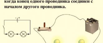
But when connected in a triangle, the ends of the windings are not connected to a common point, but are connected to the beginning of the next winding. Namely, the end of the winding of phase A (x is indicated in the diagram) is connected to the beginning of phase B, and the end of phase (y) is connected to the beginning of phase C, and, as you probably already guessed, the end of phase C (z) is connected to the beginning of phase A. It should also be remembered that if, when connected in a star, the system can be either three-wire or four-wire, then when connected in a triangle, the system can only be three-wire.
It may seem that with such a connection, electric current may begin to flow in the circuits even when the load is disconnected. However, this is a misleading impression, since with a symmetric EMF system the equality Ea + Eb + Ec = 0 will be satisfied.
Which connection of conductors is called parallel
The creation of electric current and its further transmission to consumers is carried out using an electrical circuit. These circuits are interconnected in different ways, so the question often arises which connection of conductors is called parallel and which is called serial. Both options have fundamental differences. The use of such connections in different areas allows you to make the necessary adjustments to values such as current and voltage. Mixed types of connections are successfully used in electrical and radio-electronic circuits.
Which connection is called serial
The properties of a series connection are best considered in conjunction with resistors, which may have the same or different resistance. This type of connection is called sequential when all elements are alternately connected to each other. That is, the beginning of one resistor is connected to the end of the second, and the beginning of the second is connected to the end of the third, etc. Correct calculations of a series connection affect the number and characteristics of devices connected to such a circuit.
As an example, we will consider an electrical circuit consisting of two consumers - lamps with resistance, as well as a power source and a switch for turning the power on and off.
In circuit No. 1, instead of resistors, two light bulbs with their own resistance were turned on. In addition, an ammeter is connected in series with the load to measure current, and voltmeters are connected to each lamp to measure voltage or voltage drop. The power supply provides electrical energy to the circuit, and the key serves to close and open the circuit.
In both diagrams, the ammeter is located in different places. However, when the key is closed, its readings remain the same in both cases. Consequently, the current strength in lamps Nos. 1 and 2 will be the same. The value of the current flowing in the entire circuit will be exactly the same: I = I1 = I2.
Transformerless power supply
After measuring the current, the voltage is measured on each lamp. Then this parameter is determined on two lamps at once. As a result of the measurements, the total voltage determined using a voltmeter will be the sum of the voltages of each of the lamps: U = U1 + U2. The main condition for this experiment is the presence of identical lamps, voltmeters and current sources.
Finally, it remains to investigate the characteristics of the total resistance. Based on the results of measurements of current and voltage, we can draw the following conclusion: Rtotal = R1 + R2. That is, the equivalent resistance of a circuit was actually obtained, in which all conductors connected in series can be replaced by a similar conductor with the same resistance. In the case under consideration, it will be equal to the resistance of both lamps in the circuit.
The equivalent resistance formula was obtained based on Ohm's law: I = U/R. After this, it was no longer difficult to obtain the desired result: R = U/I. As already established, the total voltage is the sum of the voltages of each lamp. With the same current strength in all sections, the following equality is obtained: U/I = U1/I1 + U2/I2. In this formula, each fraction is the corresponding resistance - both loads and the total. The total resistance value always exceeds the resistance of any of the loads included in the series circuit.
Phase and linear voltages and currents
In three-phase electrical networks, there are two types of voltages and currents - linear and phase.
Phase voltage is understood as the voltage between the beginning and end of a separate phase of an electrical receiver, and phase current is the current flowing in one of the phases of an electrical receiver.
When using a star connection (see figures above), the phase voltages will be U/a, U/b, U/c, and, accordingly, currents Ia, Ib, Ic. When using a connection of the generator windings or a load with a triangle, the phase voltages will be U/a, U/b, U/c, respectively, and the currents Iac, Iba, Icb.
Linear voltages will be the voltages between the beginnings of phases or between linear wires. Linear current will be called the current that flows in linear wires between the power source and the corresponding load.
When using a star connection, the linear currents will be equal to the phase currents, and the linear voltages with this type of connection will be equal to Uab, Ubc, Uca. When using a delta connection, the situation is the opposite - the linear and phase voltages are equal, and the linear currents will be equal to Ia, Ib, Ic.
When calculating and analyzing three-phase circuits, the positive direction of the EMF of currents and voltages is of no small importance, since the direction of these EMFs directly determines the sign in the equations that are compiled according to Kirchhoff’s law, and, as a consequence, the relationship in vector diagrams between the vectors.
Connection of electrical energy receivers
There are series and parallel connections of conductors.
A serial connection is a connection of elements in which the end of the first element is the beginning of the second, the end of the second is the beginning of the third, etc.
When receivers are connected in series, the current in the circuit does not change, and the voltage is equal to the sum of the voltages on each element, the total resistance of the circuit is equal to the sum of the electrical resistances. receivers.
I=U/R1+R2+R3=U/R
U=U1+U2+U3
A mixed connection of receivers is when there is a serial and parallel connection in a circuit or electrical circuit. In Fig. 1.1, and receivers with resistances are connected in series and connected to an energy source with voltage U. The same current I passes through all sections of the series circuit. According to Ohm’s law, the voltages at individual resistances
U1 = Ir1, U2 = Ir2, U3 = Ir3
When connecting receivers in series, the sum of the voltages at the individual receivers is equal to the voltage at the circuit terminals, i.e.
A parallel connection is a connection in which the beginnings of all elements are connected to one point, and the ends of all elements are connected to another point, and voltage is applied to both points.
With a parallel connection, the current in the circuit is equal to the sum of the currents in each branch, the voltage does not change, and the total resistance in the circuit is found through the reverse resistance and is equal to the sum of the reverse resistances in each branch.
I=I1+I2+I3=U/R1+U/R2+U/R3=U(1/R1+1/R2+1/R3)=>1/R=1/R1+1/R2+1/ R3=>I=U/R
A mixed connection of receivers is when there is a series and parallel connection in a circuit or electrical circuit.
The disadvantage of connecting receivers in series is that the voltage on each of them depends on the resistance of other receivers. In the event that one receiver fails, the current is switched off in the remaining receivers.
Kirchhoff's first law. The procedure for composing equations according to Kirchhoff's 1st law.
Kirchhoff's first law (Kirchhoff's law for knots) states:
the algebraic sum of currents in any node of an electrical circuit is equal to zero, that is
.
When composing equations according to Kirchhoff’s first law, it is necessary to specify conditionally positive directions of currents in all branches, indicating them on the diagram with arrows. In the above expression, currents with a plus sign are written with conditional positive directions from the node, and with a minus sign, currents are written with conditional positive directions to the node (or vice versa).
Kirchhoff's first law can be formulated differently: the sum of currents directed from a node is equal to the sum of currents directed to the node.
For example, for the circuit node in the figure you can write
or .
This law is a consequence of the fact that charges cannot accumulate in the nodes of a DC circuit. Otherwise, the potentials of the nodes and the currents in the branches would change.
Drawing
If, as a result of calculating an electrical circuit, a positive number is obtained for a certain current, this means that the current has a real direction according to the arrow. If a negative number is obtained, then this current is actually directed against the arrow.
Date added: 2018-04-04; ;
Methods for connecting current sources.
Serial connection.
In this circuit, the “plus” of one source is connected to the “minus” of another.
In this case, the emf of the sources adds up E0tot = E1 + E2 , so this method is used to increase the total voltage Utot = U1 + U2 . It is used when the voltage for the consumer is not enough, but one current source is able to withstand the entire load current.
2.Parallel connection
With a parallel connection, the “plus” of one source is connected to the “plus” of another (the “minuses” are connected accordingly).
If the EMF is equal, the current through the consumer does not change, but the current through each of the sources decreases, which makes it possible to maintain a large load current (if the consumer is too powerful for one source).
But at the same time, it is very important that the sources have the same parameters (that is, they are of the same type - E1 = E2, r1 = r2 ), otherwise harmful equalizing currents will pass between them, which can damage them.
A parallel connection is used when a powerful consumer needs to be powered from low-power sources.
Mixed compound
Performed when you need to increase the voltage and maintain a large load current. Those. when the EMF of one source is not enough to supply voltage to the consumer and one source is not able to withstand the entire load current
Work and power of electric current
Current work is the energy that is released when current passes through a conductor. The work done by electric current is equal to the product of voltage, current and time. The work done by electric current is measured in W sec , kW h (kW h)
A = U · I · t, [W · sec]. 1 kW h = 3600000 W sec
Power is work (energy) done (released) per unit of time:
P = A/t ;
Electrical power is equal to voltage times current. P = U I , [W, W], (Watt)
The power of any electric machine determines:
1) the ability of the machine to overcome mechanical load on the shaft;
2) electricity consumption;
3) current strength in the circuit.
Note When an electrical appliance with a power of 1 kW is connected to a household electrical network with a voltage of 220V, a current of about 4.5 A flows in the circuit.
Thermal effect of current.
The amount of thermal energy that is released when current passes through a conductor is determined by the Joule–Lenz law :
Q = I² R t, [J] (Joule).
Note 1 J = 1 W sec, 1 hp (horsepower)≈760 W
1.20. Current Density .
Current density determines the current per square millimeter of cross-sectional area of the conductor.
δ ( delta (Greek)) = I/S, [ A/mm² ]
Depending on the conductor material, insulation class, type of wiring and cooling conditions, the rated and permissible (maximum) current density is determined, exceeding which can damage the insulation
A A
Example (for aluminum wires) : δ nom ≈ 6 —— , δ add ≈ 9 ——
mm² mm² ,
At higher current densities, the insulation melts. This means that standard aluminum wiring with a cross section of 2.5 mm² is designed for a current of 16A (power about 3.5 kW). Limit current 23 – 24 A (about 5 kW). For copper wire these values are 30-40% higher.
Simplified, to select the wire cross-section, the following ratio is used: for aluminum - 1 mm² cross-section per 1 kW. For copper - 1 mm² per 2 kW of consumer power.
Transition resistance.
This is increased resistance of contacts due to their scorch, small contact area, pressing force, oxidation, etc. Due to the insufficient effective contact area, the current density increases and current is transferred through the air in the form of sparking. Heating the contacts accelerates the oxidation process, and the quality of the contact deteriorates even more.
To reduce the contact resistance, the contacts are cleaned, tinned, inserted into tips, connected with terminals, soldered, and the contact surfaces are silver-plated
Chapter. Electromagnetism.
Magnetism is the property of some bodies to attract iron objects. Such bodies are called magnets. They are natural and artificial.
Properties of magnets.
ü The poles have the greatest attractive force (in magnetism, unlike electricity, the poles are designated not (+) and (-), but north (N) and south (S) from the English words North and South).
ü Like poles repel, and unlike poles attract.
ü It is impossible to separate the poles (if you cut a magnet, you get two separate magnets with their own pairs of poles).
ü Magnets are demagnetized by heat and shock (vibration).
A magnetic field
A magnetic field is a special type of matter that is formed:
Ø Around magnets;
Ø Around moving electric charges, i.e. current carrying conductors;
Ø When the electric field changes.
Any change in the electric field generates a magnetic field and, conversely, a change in the magnetic field generates an electric one. This interaction of fields is called electromagnetic waves. Including: radio waves, visible light, ultraviolet, infrared radiation, etc.
The magnetic field is indicated by lines of force, which (unlike electrical lines of force) are always closed, located not only outside, but also inside the source and directed in the direction where the northern end of the magnetic compass needle turns, i.e. outside the source, magnetic field lines are directed from north (N) to south (S).
Note: electric and magnetic fields propagate in mutually perpendicular planes.
The magnetic field lines of a current-carrying conductor propagate in a plane perpendicular to the direction of the current. The direction of these lines of force is determined by the gimlet rule: we mentally screw the gimlet in the direction of the electric current in the conductor, then the direction of rotation of its handle will indicate the direction of the magnetic lines of force. The direction of the current is indicated by a cross (current is away from us) or a dot (current is towards us).
Note The direction of current in a conductor is determined using an arrow. If the arrow shows its plumage, then the current is directed away from us, if its tip, then towards us.