Design of SCS and LAN
It is impossible to imagine any modern office without computers, printers and other electronic equipment. Each employee needs access to local company resources, mail, the Internet, and telephone. All these problems can be solved by a well-built structured cabling system, or SCS for short.
To properly build a network, it is necessary to design an SCS; based on the results of the design and ready-made specifications, you can calculate the cost of implementation and begin installation of the SCS.
Where to start designing SCS?
Any design begins with a technical specification or design assignment. It describes the network requirements (category 5 or 6, single-mode or multimode optical cable), the number of sockets per workstation or printer, the height of the sockets, etc.
First of all, it is necessary to prepare a floor plan and indicate the location of the following objects on it:
- Computers;
- Servers;
- Network storage;
- Printers;
- Video cameras;
- Wi-FI access points;
- Controllers of engineering systems (automation, dispatching, low-current systems, etc.);
- Hatches in the floor;
- Places of interfloor transitions;
- Possible places for laying trays.
If it is necessary to equip an existing building with SCS, then design work begins with a site survey, during which the type of floors, ceilings and walls is determined. Based on the results of the survey, the types of laying of conductor products and installation of sockets (built-in, surface-mounted) are selected.
If the building has not yet been built, then the type of decoration of the premises is taken from the “Architectural Solutions” section.
After identifying all network devices and their location on the plan, you can begin to implement the project in computer-aided design systems.
At the moment, the most common CAD systems for SCS are AutoCad and NanoCad SCS.
To complete the project, knowledge of regulatory documentation on symbols and drawing rules is required.
The symbols for SCS sockets are not standardized, so different organizations have different symbols:
The NanoCad database uses the following notations:
You can use whatever you like best. In our design and installation bureau it is customary to use the following designation:
We plot the arrangement of sockets, cabinets and boxes on the plan:
Having collected the plans, we create a schematic diagram of the SCS network:
Next, the cabinets are painted in detail:
Crossings of patch panels in cabinets are carried out:
Cable log and specifications are collected.
It is better to trust the design of SCS to qualified specialists who have daily practical experience in this field. The experience of our employees is confirmed by a portfolio where you can find a variety of projects: from small offices to data centers.
Cost calculations are usually carried out per port, but all projects are individual, so we do not post the cost on the website. To determine the cost of designing a SCS, please send a request with plans and technical specifications. We will generate and send you a commercial offer as soon as possible.
Source
Why are UGOs needed in video surveillance system projects?
The video surveillance system includes a number of subsystems:
- means of recording: CCTV cameras, thermal imagers and even radar detectors
- local area network (LAN) and structured cabling system (SCS), fiber-optic communication lines (FOCL)
- control servers and software
- Storage System
- data display system (video walls, workstations for video surveillance operators)
- power supply system (redundant, uninterruptible)
- auxiliary systems: protection of equipment from the external environment, overvoltage in the power line and information transmission (the so-called “lightning protection”), information security tools, etc.
To understand someone else's technical solution, you need to have a compact view of connecting all video surveillance subsystems (on a block diagram) and a plan for the location of equipment and cable lines (on layouts). Without UGO it is extremely difficult to display this information.
Symbol of the socket on the diagram
One of the most common elements of a home's electrical system is the electrical outlet. On the diagram it may look like different symbols, which depend on the type and design of this device.
The most important stage in arranging electrical wiring is drawing up a plan for the placement of all its elements. Proper application of all components of the electrical network to the electrical diagram ensures correct planning of the required amount of materials, as well as a high level of electrical safety. A correctly drawn up diagram greatly facilitates the selection of the types of equipment needed.
Which devices require graphical symbols?
For all devices included in the technical solution for a video surveillance system, as well as for instructions on laying cable lines. Here are just some of the necessary UGOs:
| No. | Type of equipment | Conventional graphic symbol | What is it regulated by? |
| 1 | Camcorder | R 071-2017 | |
| 2 | Video camera (dome) | R 071-2017 | |
| 3 | Video camera with PTZ device | R 071-2017 | |
| 4 | Video camera in a sealed thermal casing | R 071-2017 | |
| 5 | Video camera with radio transmission | R 071-2017 | |
| 6 | Video monitor | R 071-2017 | |
| 7 | PTZ camera control panel | R 071-2017 | |
| 8 | Video storage | R 071-2017 | |
| 9 | Server | R 071-2017 | |
| 10 | Uninterruptible power supply | R 071-2017 | |
| 11 | DC Power Supply | R 071-2017 | |
| 12 | Rechargeable battery | GOST 21.210-2014 | |
| 13 | Lightning arrester | R 071-2017 | |
| 14 | Video amplifier | R 071-2017 | |
| 15 | Signal converter for transmission over twisted pair | R 071-2017 | |
| 16 | Signal converter for transmission via fiber optic communication line | R 071-2017 | |
| 17 | Signal converter for transmission over coaxial cable | R 071-2017 | |
| 18 | Lighting equipment | R 071-2017 | |
| 19 | Personal Computer | R 071-2017 | |
| 20 | Printer | R 071-2017 | |
| 21 | Additional equipment (for example, KVM extender, video wall controllers, etc.) | R 071-2017 | |
| 22 | Junction box | R 071-2017 | |
| 23 | Telephone distribution box (KRTN type) | R 071-2017 | |
| 24 | Telephone box | R 071-2017 | |
| 25 | Switching device (UK1 type) | R 071-2017 | |
| 26 | Wiring line. General image | R 071-2017 | |
| 27 | Control line | R 071-2017 | |
| 28 | Emergency evacuation and security lighting network line | R 071-2017 | |
| 29 | Voltage line 36 V and below | R 071-2017 | |
| 30 | Grounding and grounding line | R 071-2017 | |
| 31 | Metal structures used as grounding and grounding lines | R 071-2017 | |
| 32 | Laying on the cable and its end fastening | R 071-2017 | |
| 33 | Wiring in pipes. General image. | R 071-2017 | |
| 34 | Branch box | GOST 21.210-2014 | |
| 35 | Wiring in the tray | GOST 21.210-2014 | |
| 36 | Wiring in a box | GOST 21.210-2014 | |
| 37 | Wiring under the baseboard | GOST 21.210-2014 | |
| 38 | Cable end | GOST 21.210-2014 | |
| 39 | Posting goes to a higher level or comes from a higher level | GOST 21.210-2014 | |
| 40 | The posting goes to a lower level or comes from a lower level | GOST 21.210-2014 | |
| 41 | The wiring crosses the mark shown on the plan from top to bottom or bottom to top and has no horizontal sections within this plan | GOST 21.210-2014 | |
| 42 | Introductory box | GOST 21.210-2014 | |
| 43 | Pull-out box, pull-out box | GOST 21.210-2014 | |
| 44 | Equipment box | GOST 21.210-2014 | |
| 45 | Cabinet, panel, remote control, one-way service panel, local control station | GOST 21.210-2014 | |
| 46 | Cabinet, two-way service panel | GOST 21.210-2014 | |
| 47 | Optical waveguide, optical line, optical fiber, optical fiber, optical cable. General designation | GOST 2.761-84 | |
| 48 | Optical fiber cable | TIA-606-B | |
| 49 | One-piece coupling | GOST 2.761-84 | |
| 50 | Optical coupler | GOST 2.761-84 | |
| 51 | Access Point | TIA-606-B | |
| 52 | Network switch | Cisco Systems, Inc. | |
| 53 | Network router | Cisco Systems, Inc. | |
| 54 | Multilayer switch | Cisco Systems, Inc. |
Comment Videomax
Unfortunately, the regulatory documents do not contain everything necessary for the UGO project.
For example, in R 071-2017 UGO there are only three video surveillance cameras - rotating ones and those in a thermal casing are separately highlighted. But what to do with the huge number of different types of camera bodies? After all, they do not fit into these three types. And there is not enough UGO equipment for a lot of other equipment. We strongly discourage inventing your own UGO, and indicate important distinctive features of video cameras and equipment in the alphanumeric designation of the device or next to it.
Guiding Documents
In order to unify the symbols used in electrical circuits, GOST 21.614-88 “Conventional graphic images of electrical equipment and wiring on plans” was adopted back in Soviet times.
In accordance with this document, the simplest geometric shapes are used to designate all elements of the electrical network, making it easy to apply and also identify a particular element on an electrical circuit.
Strict requirements for the execution of such drawings eliminate confusion and double interpretation of all symbols printed on the diagram, which is extremely important when performing installation work in the electrical network.
Connecting a telephone socket
Between the metal contacts, a recess is required for the power wire. If it doesn’t help, then check the connection diagram, as well as the integrity and reliability of the wire contacts. Features and rules for connecting a socket Each existing type of socket has its own connection features, but below we list the features of mounting RJ and RJ type sockets, which are in great demand. We will tell you how to do this below. Almost all types of sockets are connected to the network using two contacts.
The line in such cases is also usually drawn in an open, external way; internal, when installed in a recess specially provided for this purpose.
Wire Color Coding Standards Different manufacturers have different color coding standards.
There is no need to wrap the joints with electrical tape. The communication socket for a low-current network is where the telephone connects to the communication network. The second type includes 4 wires, which is convenient, for example, for an office where a larger number of channels is needed.
The following types can be distinguished: Soviet model RTShK-4; modern RJs, usually used at home; modern RJs, used in offices for connecting faxes, laying a modem line and for other equipment; modern RJs, which are special-purpose connectors; universal or combined, combining two or more types of connectors, for example, RTShK-4 and RJ Connecting a telephone socket and IP telephony. How to install and connect a telephone socket?
Designations of elements of an open installation
The simplest two-pole electrical socket of open installation without a grounding contact is depicted on the electrical diagram in the form of a semicircle with a line drawn perpendicular to its convex part.
The designation of a double socket differs from the previous one in the presence of two parallel lines. The graphic symbol corresponding to a three-pole product is a semicircle, the convex part of which is adjacent to three lines converging at one point and arranged like a fan.
To designate a socket with a grounding contact, a horizontal line is added to its image, which is tangent to the top point of the semicircle.
Fun conventions in design projects
There is an interesting point related to how differently designers designate the same elements in their projects. Sometimes it seems to me that every time while drawing a design project, the designer sits and thinks about how to designate this or that element. As the hand goes, so it draws.
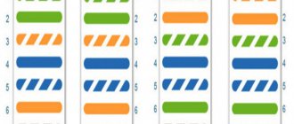
For example, here is the most common (albeit not GOST) designation of an outlet:
The number 2 means that the socket is double. Sometimes they draw two socket icons next to each other to show that it is double, I like this option a little better.
Here is a designation closer to the standard:
Very often the designation of a socket in the form of a “patch” is found.
But everyone comes up with Internet sockets and TV sockets as they want. Many options are downright funny. The easiest option is to write RJ45, INT or LAN above the socket. 2LAN respectively, double socket.
A very funny option is to simply write @ instead of indicating a socket. And instead of TV socket write TV.
It’s better to fit this sign into at least a square.
I like this option best:
Switches.
There are the fewest options here; usually the switch designations are similar to the following:
Option of switches from the designers of socket outlets:
For all other elements, such as sensors for water leakage, movement, temperature, smoke, gas - everyone draws in different ways. If the appearance of the icon reflects its purpose or it is clearly shown in the legend, then this is already good and understandable.
Today they brought me a design project in which the designer, it seems, firstly, has never seen a single project before, and secondly, cannot guess to type “outlet designation on the plan” into the search engine. Well, thirdly, he doesn’t give a damn about whether anyone will understand anything in his drawing.
Here is a list of symbols. A person certainly doesn’t have much imagination.
Where did this designation of a switch come from, like crossed out horizontal lines?
What is an "antenna"? If this is television, then why 2 sockets?
What is “Wi-Fi” and why two sockets?
Most often, elements (sockets and switches) are marked exactly in their places on the walls, this turns out beautifully and neatly. Of course, they are not drawn in real scale (with a side of 60mm), but 2-3 times larger, but still everything is clear. But sometimes the designer becomes very afraid that such small elements will not be visible, and makes them several times larger, and even moves them away from the wall. It turns out like this:
Dimensional lines somehow help to navigate this clutter, but it looks very sloppy. In these types of projects, I re-paint all the outlets and switches (and sometimes the lights) to make it look clean and tidy. And, of course, tooth-breaking pink, I don’t know for what reasons. Apparently my favorite color.
I'm not talking here about the fact that the designations must comply with GOST. If you need designations in accordance with GOST, then they can be easily found by making the appropriate request in a search engine (I’ll make the task easier - see here). The main thing is that the drawing is clear and understandable. Many people have big problems with this; people just can’t understand how to draw in a way that is clear. It turns out this nonsense:
Another common mistake: sockets with 6, 7 or more modules. There are no such frames! How can a designer not know this? And if a certain collection is selected that has such frames, this should be indicated in the project. Here this “i in a circle” icon means an Internet socket.
And by the way, I am far from understanding what the dimensions around this block of sockets mean: 95 and 1210.
By the way, “WF in a circle” is a Wi-Fi router. Without any indication of the height of its installation and what sockets are needed for it. At least they drew an electric one.
Let's continue. Here is a small battery of sockets behind the TV:
In the pancake block, the strange elements on the left are single and double internet outlets. How do we designate an Internet outlet? - thought the designer - Let's draw a line, on it a rectangle, and on it two sticks up. For a double rosette, draw two such elements one above the other.
Next is this block:
What do you think the red square is? What is a rectangle with a zigzag? Let's look at the legend.
It turns out that the red square is some kind of Mac charging unit. I find it difficult to say what it is. How to logically label a USB outlet? Maybe draw a regular socket and write “USB” next to it? No, we’ll take our strange designation for an Internet outlet and add a third stick to it.
To avoid confusion between a USB socket and a USB-C socket, it is designated as a rectangle with “teeth”.
Even ordinary electrical outlets have been designated so that the layout of the outlets resembles a cemetery.
Next project.
They didn’t think much about it, they drew a square with letters. B - switch, BB - two-key switch. VK - push-button switch. P - switch. Further more fun: Per - cross switch. PerPer no, for some reason. It's even more fun:
I like MV, MP and MPer the most. TRIAC dimmer for RGBW strip - all in one place.
In the same design project, lights, sockets, switches, electrical outlets and furniture were applied on one sheet. The result is a jumble of lines and symbols. The symbols do not fit on the drawing, so they are made into callouts.
From such a congestion of lines, it seems to me that the installer’s brain will boil, even if the drawing is printed on A2.
More different and interesting symbols can be found in my article Errors in design projects.
46, total, today
Related posts:
- Designers! Read it please! Mistakes in Design Projects I deal with design projects all the time. Based on the design project,...
- Selection of Wirenboard equipment and system design I’ll tell you a little about how to design a Smart Home system on…
- Payback of the electrical and Smart Home project For me, all the advantages of preliminary implementation of the electrical, low-voltage and...
- Comparison of Smart Home systems: Larnitech, Wirenboard, Beckhoff, Z-Wave, EasyHomePLC By popular demand, I will write a short comparison of Smart Home systems, with…
- Video surveillance systems: analogue, digital, AHD and others I have been involved in video surveillance since 2008. I was selecting systems then...
- What can be installed from a Smart Home Since not everyone understands what a modern…
- Smart Home and clouds Actually, it has long gone into the clouds. One can only state that…
Sockets for hidden electrical wiring
Concealed wiring is the most common type of home electrical network. To install it, devices are used that are built into the wall using special mounting boxes.
The only difference between the designation of such rosettes and the above figure is the perpendicular, lowered from the middle of the straight segment to the center of the circle.
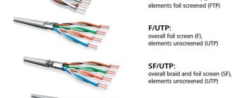
Internet cable
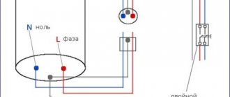
Installation begins with installing the router in a low-current switchboard and connecting it to a 220V power outlet.
Next, a 4-pair UTP series 5E cable is laid in a separate cable channel or groove not connected to power lines.
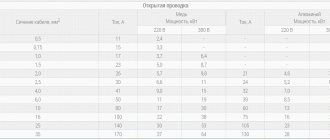
This cable provides connection speeds of up to 1 Gigabit per second over a distance of up to 100m. Here are its technical characteristics:
There are shielded and unshielded varieties. Foil acts as a shield in networks where there is normal grounding.
One such 5E cable (4 pairs) can only connect two sockets. In this case, 2 pairs will be involved separately.
Installation is carried out with a single wire directly from the switchboard to the socket box. Lead the cable into the installation box and leave the necessary margin - from 15 cm or more.
Devices with increased protection from dust and moisture
The sockets considered do not have a high level of protection against the penetration of solid objects into their housing, as well as moisture. Such products can be used in interior spaces where operating conditions exclude such effects. As for devices intended for installation outdoors or, for example, in bathrooms, according to the accepted classification, their degree of protection should be below IP44 (where the first digit corresponds to the level of protection against dust, the second - against moisture).
Such sockets are indicated on the diagram in the form of a semicircle completely shaded in black. As in the previous case, two-pole and three-pole waterproof sockets are indicated by the corresponding number of segments adjacent to the convex part of the semicircle.
Installation of an internet outlet
First remove the cover from the socket and pull out the caliper for ease of installation.
If the design of the socket allows, the frame can be mounted initially on the socket box. Thanks to the grooves in the frame, you can easily adjust its horizontal position.
Use 3*25mm screws to pre-tighten the entire structure. At the same time, you check the accuracy of the installation with a Pocket Electric level and tighten the screws completely.
Manufacturers have recently begun to make frames from aluminum alloy; they are, of course, stronger in design, but will not be magnetic to the level. You will have to support it with one hand.
Next, bite off and leave a supply of wire in the socket, a maximum length of 15 cm. Remove the top layer of insulation from the UTP cable.
To remove the insulation, so as not to damage the conductors, it is better to use a special tool - a stripper. But you can do all this carefully and with an ordinary stationery knife.
The top layer of the cable must be cleared to a length of no more than 2.5 cm. Cut off the excess thread in this case that goes between the cores.
A strong thread in twisted pair cables, often used to facilitate opening the sheath over long lengths. It’s even called that – a breaking thread. In telephone cables, it separates bundles and layers.
Lightly unravel the veins individually. Next, pull out the inner part of the socket with the contacts.
As a rule, any brand, be it a TV, an Internet outlet or a regular 220 Volt, should come with instructions.
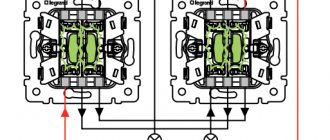
Instructions for the Schneider Electric Unica internet socket – Instructions for Legrand –
Switches
The switch in the diagram is indicated in the form of a circle, to which a line is drawn at an angle of 45 with an inclination to the right side, having one, two or three perpendicular segments at the end (depending on the number of keys of the switch depicted).
The image of the hidden installation switches is the same, only the segments at the end of the inclined line are drawn in both directions from it at the same distance.
Moisture-resistant products are indicated by a black circle.
It is worth paying attention to the image of pass-through switches, which resembles two ordinary switches, mirrored from the center of one circle.