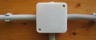
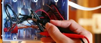
Junction box for electrical wiring
According to the PUE standards, branching and connecting places for wires in the house should be located inside the housings of electrical appliances, in special niches in partitions and ceilings, or in junction boxes. That is, all such switching nodes must be additionally insulated in case of overheating and fire.
In principle, you can do without a box. But then you will have to connect each outlet to its own separate wire from the house electrical panel without twists or other connections along its entire length. As a result, the cost of such electrical wiring due to the large total footage of the lines will be considerable. Plus, the grooves and boxes will need to be larger in size, since in some places several electrical wires will be laid in a bundle.
Cable channels
Cable channel, stylized as wood
In the last decades of the 20th century, a completely new material appeared, which firmly occupied a niche in the production of almost any things and objects that people use. We are talking about plastic, namely polyvinyl chloride (PVC) . A special feature of this material is its dielectric properties - it does not conduct current at all, which is why insulating materials began to be made from it. Actually, the modern cable channel is designed for this; it also protects the wiring from external mechanical damage - remember cats who already love to feast on wires.
Such an inhabitant in the house can cause a short circuit
Box is a common name that is assigned to structures that hide various communications from view. They usually have a rectangular shape, but today this fact is becoming blurred - you can find semicircular models made to resemble baseboards, or stylized sweat pipes. All this allows you to select the best solutions for different interiors.
Skirting system with cable duct
So, it is a tube-box of a certain length, inside of which there is free space in the form of channels or simply emptiness. The box has a removable front panel, which is needed for hidden installation and cable management. Depending on the model of the box, the front side can have a different shape; it is connected to the base through latches running along the entire length of the product. The base of the cable channel itself is flat so that it can be tightly attached to the wall. It may have mounting holes, although most models require you to drill them yourself.
Ventilated cable channel
Cable channels are ventilated and closed. The first option is used where overheating of the conductors is not permitted under any circumstances. Based on their purpose, these products are divided into the following options:
- Skirting boards - we have already mentioned them above, the wires in them are laid in the corner of the room, and the shape of the product is such that you can lay several independent routes.
- Floor-mounted – you rarely see them in simple houses and apartments; they are distinguished by their high strength. The wires in them are laid directly on the floor.
- Wall-mounted - the most common type, which can be thrown along the walls from the junction box to anywhere in the room.
- Corner - in fact, this model has the same rectangular shape, but consisting of two corners, one of which is the base, and the second is the front panel. Another option is possible in the form of a triangle; in this form it somewhat resembles a plinth, but only for vertical installation.
- Ceiling - in many ways they are similar to wall ones, but can be additionally equipped with grooves for installing LED strips or holes for neat installation of spotlights. Ceiling boxes can be stylized to resemble ceiling beams, which at the same time makes it possible to implement interesting design solutions in the interior.
Cable channels stylized as ceiling beams
The boxes can also be flexible - they are made in the form of corrugation or chain. Interesting are chain models that consist of individual PVC links. The wires run inside, and due to the peculiarity of the structure, remain visible. They are practically not used in everyday life. They are needed for industrial equipment that does not have a permanent location. As a result, the moving cable is reliably protected.
Chain flexible cable channel
For other models, additional fittings are provided that allow turning. LED boxes can be noted as a separate line. They already have a built-in backlight, you can also hide the wires and place a power supply for the LEDs.
Cable channels may also differ in size. The smallest ones are intended for communication wires, signal and television cables, thick, large boxes are needed for electrical installation work.
Interesting to know! Plastic boxes are used not only for their intended purpose. For example, they can contain a route running from the air conditioner to the street block. A fast, beautiful and neat solution.
Multi-section semicircular cable channel
If it is necessary to lay wires isolated from each other, multi-section boxes are used. You can see an example of such a product in the photo above. What distinguishes them from other models is the presence of partitions inside. When choosing such a solution, it is worth remembering that groups of wires are more difficult to lay in them, which is affected by limited space. Multi-section trays will be much stronger than conventional ones, since the partitions act as stiffeners.
Cable channel in the form of platbands for door and window openings
A separate type of cable channels are models made in the form of platbands for door and window openings. It also has a semicircular shape, several sections inside and a special connecting element through which it can be connected at an angle of 45 degrees.
Such a cable channel on a wooden wall, and it will be almost invisible
The color range in which cable channels are manufactured is quite extensive. The classic version is white, everything else is usually stylized to resemble different types of wood. This choice of manufacturers is due to the fact that wooden elements are inherent in many styles and interiors.
Prices for cable channels
Cable channel
Video – Installation of cable channel
Kinds
Distribution boxes (also known as junction boxes, switch boxes and branch boxes) differ in design, appearance, material of manufacture and degree of protection, as well as the presence or absence of terminals inside. For each case, you should select your own option, otherwise this element of electrical wiring will be of little use.
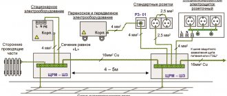
Types of boxes and wiring options
By installation method
According to the installation method, the boxes differ in:
- open;
- hidden.
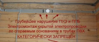
The former look more presentable and are used when laying electrical wires openly. The second ones are installed inside building structures and then covered with decor. For example, it is recommended to do electrical wiring in a wooden house with your own hands using open installation. But when laying cables in steel pipes under the finishing, hidden wiring is also possible using appropriate electrical installation products.
Step-by-step instructions for terminal wiring
By type of material
Boxes for arranging branching points for wires are made from non-flammable plastic or metal. They are usually selected in accordance with the braiding (insulation) material of the electrical wiring. If the cable is armored or laid in a metal pipe, then the junction box must also be made of metal. For other cases, it is better to choose a plastic analogue.
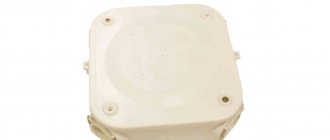
Other boxes
The degree of protection of junction boxes is IP from “20” to “68”. For dry, heated rooms, IP “20” or “30” is sufficient. But usually for domestic conditions, in a cottage or garage, they choose the option with IP “55”. But for bathrooms and outdoor installation, you should purchase an electrical installation product with IP from “65” to “67”. The number of inputs can be from two to sixteen.
If the degree of protection is increased, then the cable openings are equipped with glands. But usually they are simply made in width to match the thickness of the inserted wire. The inputs can be located both in the sides of the product and on its bottom (the inner side in contact with the wall).
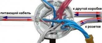
Distribution of wires in the box
Wire connection methods
In a box, conductors can be connected in different ways. Some of them are more difficult to implement, others are easier, but if implemented correctly, they all provide the required reliability.
Twist
The most popular method among folk craftsmen, but the most unreliable. It is not recommended by the PUE for use, as it does not provide proper contact, which can lead to overheating and a fire. This method can be used as a temporary method, for example, to check the functionality of the assembled circuit, with mandatory subsequent replacement with a more reliable one.
Correct twisting of electrical wires
Even if the connection is temporary, everything must be done according to the rules. The methods for twisting stranded and single-core conductors are similar, but have some differences.
When twisting stranded wires, the procedure is as follows:
- the insulation is stripped to 4 cm;
- the conductors unwind by 2 cm (item 1 in the photo);
- connect to the junction of untwisted conductors (pos. 2);
- the veins are twisted with your fingers (position 3);
- the twist is tightened with pliers or pliers (pos. 4 in the photo);
- insulated (insulating tape or heat-shrinkable tubing placed before the connection).
Connecting wires in a distribution box with one core using twisting is easier. The conductors, stripped of insulation, are crossed and twisted with fingers along their entire length. Then take a tool (pliers and pliers, for example). In one, the conductors are clamped near the insulation, in the second, the conductors are intensively twisted, increasing the number of turns. The connection point is isolated.
Twist with pliers or pliers
Twist with mounting caps
Twisting is even easier using special caps. With their use, the connection is more reliably insulated and the contact is better. The outer part of such a cap is cast from flame retardant plastic; a metal conical part with a thread is inserted inside. This insert provides a larger contact surface, improving the electrical performance of the connection. This is a great way to connect two (or more) wires without soldering.
Twisting wires using caps is even simpler: 2 cm of insulation is removed, the wires are slightly twisted. A cap is put on them and turned with force several times until the metal is inside the cap. That's it, the connection is ready.
Connecting wires using a cap
Caps are selected depending on the cross-section and number of conductors that need to be connected. This method is more convenient: it takes up less space than conventional twisting, and everything fits more compactly.
Connecting conductors in a junction box with caps
Soldering
If you have a soldering iron in the house and you know how to handle it at least a little, it is better to use soldering. Before twisting, the wires are tinned: a layer of rosin or soldering flux is applied. The heated soldering iron is dipped in rosin and passed several times over the part that has been stripped of insulation. A characteristic reddish coating appears on it.
Soldered wires
After this, the wires are twisted as described above (twisting), then they take the tin on a soldering iron, heat the twist until the molten tin begins to flow between the turns, enveloping the connection and ensuring good contact.
Installers do not like this method: it takes a lot of time, but if you are connecting the wires in the junction box for yourself, spare no time and effort, but you will sleep peacefully.
Welding wires
If you have an inverter welding machine, you can use a welding connection. This is done on top of the twist. Set the welding current on the machine:
- for a cross section of 1.5 mm2 about 30 A,
- for a cross section of 2.5 mm2 - 50 A.
The electrode used is graphite (this is for welding copper). Using grounding pliers, we carefully cling to the upper part of the twist, bring the electrode to it from below, briefly touch it, achieving ignition of the arc, and remove it. Welding occurs in a fraction of a second. After cooling, the joint is insulated. Watch the video for the process of welding wires in a junction box.
Terminal blocks
Another connection of wires in the distribution box is using terminal blocks - terminal blocks, as they are also called. There are different types of pads: with clamps and screw ones, but, in general, the principle of their design is the same. There is a copper sleeve/plate and a wire fastening system. They are designed in such a way that by inserting two/three/four conductors into the right place, you connect them securely. The installation is very simple.
Screw terminal blocks have a plastic housing in which the contact plate is fixed. They are of two types: with hidden contacts (new) and with open contacts (old style). In any of them, a conductor stripped of insulation (length up to 1 cm) is inserted into the socket and clamped with a screw and a screwdriver.
Connecting wires in a junction box using terminal blocks
Their disadvantage is that it is not very convenient to connect a large number of wires in them. The contacts are arranged in pairs, and if you need to connect three or more wires, you have to squeeze two wires into one socket, which is difficult. But they can be used in branches with significant current consumption.
Another type of block is Vago terminal blocks. These are pads for quick installation. There are mainly two types used:
- With flat spring mechanism. They are also called disposable, since their reuse, if possible, is with a significant deterioration in the quality of contact. The point is in the internal structure: in the body there is a plate with spring petals. When inserting a conductor (single-core only), the petal bends, clamping the wire. Providing contact, it cuts into the metal. If the conductor, with due effort, can be pulled out, then the petal will no longer take its previous shape. That is why this type is considered disposable. Despite this, the connection is reliable and they can be used. There are also special terminal blocks of the same shape, but in a black housing. They contain electrical paste inside. These connectors are necessary if you have to connect copper and aluminum, which simply do not fit together due to the active electrochemical processes that occur between them. The paste prevents oxidation, allowing the two metals to be joined easily.
Vago terminal blocks - Universal with lever mechanism. This is perhaps the most convenient connector. Insert the bare conductor (the length is written on the back side), press the small lever. The connection is ready. If you need to reconnect the contact, lift the lever and remove the wire. Comfortable.
The peculiarity of these terminal blocks is that they can only be used at low currents: up to 24 A with a copper wire cross-section of 1.5 mm, and up to 32 A with a cross-section of 2.5 mm. When connecting loads with high current consumption, the wires in the junction box must be connected in a different way.
Crimping
This method is possible with special pliers and a metal sleeve. A sleeve is put on the twist, it is inserted into the pliers and clamped - crimped. This method is just suitable for lines with a large ampere load (such as welding or soldering). Watch the video for details. It even contains a model of a distribution box so it will be useful.
Installation
The junction box is installed on the wall with a lowering of 10–30 cm from the ceiling. Moreover, this is done in such a way that there is open access to its lid. Checking the condition of the wires should be carried out on a regular basis.
Step-by-step instruction
Installation of the junction box is carried out in four simple steps:
- Fastening the box to the wall according to the wiring diagram.
- Planting wires inside and then connecting them to each other.
- Checking the assembled electrical network.
- Closing the electrical installation product with a cover.
The junction box is secured using self-tapping screws or plaster (if it is recessed into the wall).
Arrangement of input cables in the box
Wire connection methods
According to the PUE, the electrical wires inside can be connected:
- twisted;
- soldering;
- welding;
- terminals;
- crimping.
How to properly connect wires in a junction box
Twist
Twisting is the fastest and at the same time the most unreliable way to connect indoor electrical wiring. To cover the exposed wires, special plastic caps or electrical tape are used.
Twist connection method
Soldering
Soldering is done with tin on top of the pre-twisted wire. This connection is much more reliable and durable. However, such installation takes a lot of time.
Welding wires
For welding you need an inverter welding machine. This method is even more reliable and more complex, but as a result, the two connected cores actually turn into a single solid one. It is recommended to choose it only in special cases. For example, when grounding is done in a private house under a powerful load or additional pumps and uninterruptible power supplies are connected for a gas boiler.
Terminal connection
If the wires are made of different materials, then it is best to use terminals with screw or spring clamps. The terminal connection is extremely simple to make; you only need a screwdriver. The most important thing here is not to overtighten the clamp bolts.
Terminal connection of wires
Crimping
When crimping, press pliers and sleeves are used, made of the same metal as the cores, and sized to match the thickness of the wires being connected. Some craftsmen use pliers for this, but such connections are rarely reliable. It's better not to experiment.
Crimping connection method
Wiring diagrams
To avoid any confusion when connecting electrical wires, it is worth preparing in advance the wiring diagrams for all installed junction boxes. This drawing should indicate “from where and where” each core goes. In general, it is advisable to use different colored wires to avoid confusion.
Wiring diagram
General information
A distribution box is a type of electrical product in which switching and branching of electrical wires are organized outside or inside a room for laying an electrical network.
In everyday life, this term also corresponds to other names:
- soldered;
- branch;
- exceptional.
These are synonyms that denote one product, and not individual types of boxes.
Electricity consumers determine the division of electrical wiring in buildings and premises into different groups. Correct installation of boxes ensures uninterrupted power supply and reduces financial costs without the need for a separate cable for each electrical device. With even distribution of wires, the level of fire safety increases due to the insulation of flammable materials and connections located in the walls.
In addition, the electrical design provides ease of repair and the ability to expand the electrical circuit by adding new branches. As a result, everything looks beautiful and aesthetically pleasing.
Distribution boxes provide protection of connections from:
- dust – during installation at industrial facilities;
- water – for installation in areas with high humidity;
- mechanical damage – for placing cables outdoors;
- sudden temperature changes - when installing in wooden buildings or on walls with flammable materials.
Security measures
The most important thing when installing a distribution box is compliance with basic safety measures. Wires of different metals should be connected only through adapters, and not directly. Plus, do not confuse phase with neutral and ground. And before closing the junction box with decor, if a hidden wiring option is chosen, you should check the entire system for functionality.
Standard color scheme for phase identification