Design Features
Installing electrical wiring without junction boxes is a technique that has appeared relatively recently. Despite this, in some cases this installation scheme does not contradict the basic documents of PTEEP and PUE. At the same time, the method itself still causes controversy in professional circles.
In this case, the wiring diagram has some differences from the one used when installing junction boxes. Without distribution boxes, the electrical wiring is also powered from a switchboard with an automatic circuit breaker. From it the wire is directed to the first socket and then stretches in a loop to the others.
The three-core cable (neutral, phase and ground) suitable for the first outlet is cut. Zero and phase are broken. But the grounding cannot be interrupted; it must reach the contacts of the third socket. Therefore, the two stripped wires must be connected to the corresponding incoming contacts. Then the zero and phase are sent in a loop to the next socket, connecting and tightening well with a screwdriver at the input contact.
In this case, the grounding cable is stripped. The cleaned wire is bent in half. Thus, we get two wires in contact with each other, which have a common core.
After this, a piece of wire is stripped on both sides. One end must be attached to the bent ground. As a result, we get three bare areas, which we press with a special sleeve and insulate. We bring the second end to the contact of the socket intended for grounding and clamp it. Thus, we avoid gaps and fulfill everything according to the documentation requirements.
After this, we connect the wire through the groove to subsequent sockets. In this case, a phase interruption and zero occurs. Terminal blocks are used to secure them.
It is worth noting that such installation of electrical wiring can cause some difficulties when using cheap sockets. Such products often have weak contacts. Because of this, the wires in them can become very hot, causing the wiring to burn out or cause a fire. Also, the ends of the cables may fall out of the contacts, leading to disruption of the power supply circuit in other outlets.
To avoid a similar situation with such a wiring installation scheme, the grounding wire (both zero and phase) is cut through. In addition, you can crimp cables, making taps not only for grounding, but also for phase and neutral. In this case, the sleeves used for crimping must be insulated. They are placed in the socket box, and the taps are then connected to similar contacts.
In the described wiring diagram, the socket box will serve as a distribution box. Therefore, the use of junction boxes will not be carried out here.
In order for such installation to take place quickly and without problems, experts recommend buying socket boxes that are longer. This way they will fit all the necessary wires.
For branch circuits, you need to consult an electrician before installing them yourself. However, you need to know that installing cables in this way is used in certain cases.
Electrical wiring with distribution boxes
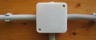
Typically, in electrical installations, a distribution box is used, through which the supply wires are connected to the wires going to sockets, switches, lamps, and so on.
Electrical wiring with junction box
If there are many outlets in the room, intermediate boxes are added. But, it should be taken into account that the box must have a correct and high-quality connection and there must be free access.
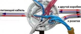
The diagram below shows an electrical installation with boxes, where the power wires come into the distribution box, and from it to the socket and intermediate box.
Wiring diagram with junction boxes
When to use
This installation method is recommended in cases where the walls have expensive finishing. In this case, the wiring is carried out under the floor and without installing additional electrical equipment in the walls in the form of a junction box.
The PUE also indicates the moments when only this wire distribution scheme is used. According to the documentation, the ban on inserting cables into the junction box applies to lines that supply:
- electric stoves;
- air conditioners;
- heating boilers;
- all devices that consume a lot of electricity during their operation.
In these situations, a circuit breaker should be installed in the distribution panels for protection. A separate cable line is laid from it. The result is a circuit for powering a separate group of devices.
Advantages and disadvantages
The main advantage of using this wiring diagram is the absence of distribution boxes, which are usually installed at the top of the wall. As a result, there is no damage to the appearance of the finish.
It is worth noting that distribution boxes hidden under wallpaper or plaster can cause problems if there is a network fault. This is due to the fact that in order to get to the box, you will need to destroy part of the decorative design of the area above it. There are no such problems when using this installation scheme.
In addition, the advantages of this installation method include:
- installation costs for electrical wiring are significantly reduced;
- there is no need to form holes in the walls for distribution boxes;
- ease of installation and its ease.
However, it is worth noting that such cable installation requires a person to comply with all safety requirements.
In this case, all connection points must be accessible for routine inspection and necessary repairs. In this scheme, the weak point is the cable connections. Another disadvantage is that installation requires a large length of wires.
Despite a number of advantages, installing wiring in a house without using junction boxes is considered a necessary measure. When installing electrical wiring, distribution boxes increase the safety of its operation and also improve the reliability of the electrical network.
As you can see, electrical wiring without junction boxes is a wiring option that has some positive aspects. However, we should not forget about the disadvantages. Before installing wires according to such a scheme, you need to weigh all the pros and cons in order to make the optimal and correct decision in each specific situation.
Video on the topic
We invite you to watch a video - assembling a connection diagram for two pass-through switches without a distribution box:
Assembling a connection diagram for five pass-through switches without a distribution box:
Many may be interested in another video from this series - lighting control from three places using conventional single-key switches:
In this article we will take a closer look at how to connect pass-through switches without a branch box .
After publishing a series of articles and videos on pass-through switches, many letters began to arrive in the mail from readers of this site with the question: “Is it possible to switch it off without a branch box?”
Yes, you can do without a branch box . There are two main options here:
1. On pulse relays.
If the electrical panel is installed in an apartment and there is additional space for one module, then you can use a pulse relay for installation on a DIN rail.
The switches are connected by two wires in parallel and these two wires are led directly into the panel; the wire from the lamp is also led directly into the panel. In this circuit, the switch is included in the control circuit; the load current does not flow through it, so a wire of a smaller cross-section can be used. The load is directly controlled by a pulse relay.
If there is no space in the panel, then relays are produced for local installation in socket boxes, branch boxes, behind the ceiling; Connection diagrams depend on the specific model and are usually indicated in the instructions for them.
For more information about pulse relays, read the series of articles and videos in the Lighting section.
2. On pass-through switches.
First, let's remember the diagram of pass-through switches from two places.
Pass-through switches close and open the phase wire circuit, connecting and disconnecting it from the lamp socket. At the same time, load current flows through the contacts of the switches. Therefore, it is necessary to use a cable of the appropriate cross-section.
For more information on pass-through switches, see the series of publications, links to which you will find at the bottom of this article. If you want to become an expert in this matter and learn how to assemble any lamp control circuits from different places, the book “Lighting Control from Several Places” will help you.
In it, the topic of pass-through and crossover switches is discussed inside and out.
So, a diagram for connecting pass-through switches from two places without a branch box.
Instead of a junction box, all wires are brought together into the first socket box. Those. power from the electrical panel (zero, phase, grounding) to the socket box, a wire from the lamp to the socket box, and a wire from the second pass-through switch also to the same socket box.
Only in this case, a deeper socket box is needed, or the hole for it is made deeper, and the bottom is cut out in a standard socket box (so that there is somewhere to disconnect the wires).
The neutral and grounding wires from the electrical panel are connected in the first socket box, respectively, with the neutral and grounding wire from the lamp. They isolate themselves and hide in the socket.
The red wire from the lamp is connected to the red wire from the second socket box, insulated and also left in the socket box. This wire will supply the phase to the lamp. The remaining wires are connected to the terminals of the pass-through switches.
The central contact is indicated in the diagram by number 1 . Wire colors may differ from those shown in the diagram. The main thing is to understand the principle.
For a better understanding of the operation of the pass-through switch circuit from two places without a branch box, watch the video.
Wiring diagram for pass-through switches from three places without a branch box.
The three-location circuit uses a crossover switch. It is installed between two pass-through switches, in socket 2 in the diagram.
The pass-through switch, when you press a key, transfers contact 1 between two others - 2 and 3 .
A crossover switch switches contacts crosswise. In one position of the key, contact a is connected to contact c , and contact b is connected to contact d . In the other, contact a is connected to d , and contact b is connected to contact c , i.e. criss-cross.
In this simple way you can connect pass-through switches from two, three or more places without a branch box.
In conclusion of this article, I suggest watching a video that more clearly demonstrates the operation of a pass-through switch circuit from three places without a branch box.
Subscribe to my YouTube channel and be the first to receive new electrical videos! Don't forget to click LIKE.
And finally, a list of materials on feed-through and crossover switches that I recommend studying.
