Purpose
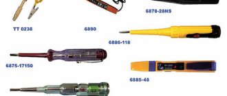
1. Voltage indicators are designed to determine the presence or absence of voltage on live parts of electrical installations.
2. General technical requirements for voltage indicators are set out in the state standard.
Voltage indicators above 1000V
Operating principle and design
3. Voltage indicators above 1000 V react to capacitive current flowing through the indicator when its working part is introduced into the electric field formed by live parts of electrical installations that are energized, and the “ground” and grounded structures of electrical installations.
4. Indicators must contain the main parts: working, indicator, insulating, as well as a handle.
5. The working part contains elements that react to the presence of voltage on the controlled current-carrying parts.
The working part may contain an electrode tip for direct contact with the controlled current-carrying parts and not contain an electrode tip (non-contact type indicators).
The indicator part, which can be combined with the working part, contains elements of light or combined (light and sound) indication. Light and sound signals must be reliably recognizable.
The working part may also contain a body for its own serviceability monitoring. Control can be carried out by pressing a button or be automatic by periodically sending special control signals.
6. The insulating part can be composed of several links. To connect the links to each other, parts made of metal or insulating material can be used. It is permissible to use a telescopic design, but spontaneous folding must be prevented.
7. The handle can be one piece with the insulating part or be a separate link.
8. The design and weight of the signs must ensure that one person can operate them.
9. The electrical circuit and design of the indicator must ensure its operability without grounding the working part of the indicator, including when checking the absence of voltage, carried out from telescopic towers or from wooden and reinforced concrete supports of 6 - 10 kV overhead lines.
10. The voltage indicator indication voltage should be no more than 25% of the rated voltage of the electrical installation.
11. The time for the first signal to appear after touching a live part under voltage equal to 90% of the rated phase voltage should not exceed 1.5 s.
12. The working part of the pointer for a certain voltage should not react to the influence of neighboring circuits of the same voltage.
Performance tests
13. During operation, mechanical tests of voltage indicators are not carried out.
14. Electrical tests of voltage indicators consist of testing the insulating part with increased voltage and determining the indication voltage.
For voltage indicators with a built-in power source, its condition is monitored and, if necessary, the batteries are recharged or the batteries are replaced.
15. When testing the insulation of the working part, voltage is applied between the tip electrode and the screw connector or at the boundary of the working part.
16. When testing the insulating part, voltage is applied between the element of its articulation with the working part (threaded element, connector, etc.) and a temporary electrode placed at the restrictive ring on the side of the insulating part.
17. The indication voltage of the pointers is checked as follows: the voltage of the test installation smoothly rises from zero to the value at which the light signals begin to correspond to 25%.
18. The standards and frequency of electrical tests of indicators are given in the table.
Terms of use
19. Before you start working with the pointer, you need to check its serviceability.
The serviceability of indicators that do not have a built-in monitoring device is checked using special devices, which are small-sized sources of increased voltage, or by briefly touching the electrode-tip of the indicator to live parts that are known to be energized.
20. When checking the absence of voltage, the time of direct contact of the working part of the indicator with the controlled current-carrying part must be at least 5 s (in the absence of a signal).
It should be remembered that although some types of voltage indicators can signal the presence of voltage at a distance from live parts, direct contact with them by the working part of the indicator is mandatory.
21. In electrical installations with voltages above 1000V, the voltage indicator should be used with dielectric gloves.
Voltage indicators up to 1000V
Purpose, principle of operation and design
22. In electrical installations with voltages up to 1000V, two types of indicators are used: double-pole and single-pole.
Bipolar indicators that operate when active current flows are designed for electrical installations of alternating and direct current.
Single-pole indicators operating when capacitive current flows are intended for electrical installations with alternating current only.
The use of two-pole indicators is preferable.
The use of test lamps to check the absence of voltage is not allowed.
23. Two-pole indicators consist of two housings made of electrical insulating material, containing elements that react to the presence of voltage on the controlled live parts, and elements of light and (or) sound indication. The housings are connected to each other by a flexible wire at least 1 m long. At the points of entry into the housings, the connecting wire must have shock-absorbing bushings or thickened insulation.
Case sizes are not standardized and are determined by ease of use.
Each body of a two-pole indicator must have a rigidly fixed tip electrode, the length of the non-insulated part of which should not exceed 7 mm, except for indicators for overhead lines, in which the length of the non-insulated part of the tip electrodes is determined by technical conditions.
24. A single-pole indicator has one body made of electrical insulating material, which houses all elements of the indicator. In addition to the electrode tip that meets the requirements of clause 2.4.25, there must be an electrode on the end or side of the housing for contact with the operator’s hand.
The dimensions of the case are not standardized; they are determined by ease of use.
25. The indicator indication voltage should be no more than 50V.
Light and sound signals may be continuous or intermittent and must be reliably recognizable.
26. Voltage indicators up to 1000V can also perform additional functions: checking the integrity of electrical circuits, identifying phase wires, determining polarity in DC circuits, etc. In this case, the pointers should not contain switching elements intended for switching operating modes.
Expanding the functionality of the indicator should not reduce the safety of operations to determine the presence or absence of voltage.
Performance tests
27. Electrical tests of voltage indicators up to 1000 V consist of an insulation test, determination of the indication voltage, checking the operation of the indicator at an increased test voltage, checking the current flowing through the indicator at the highest operating voltage of the indicator.
If necessary, the indication voltage in DC circuits is also checked, as well as the correct polarity indication.
The voltage gradually increases from zero, while the values of the indication voltage and the current flowing through the indicator at the highest operating voltage of the indicator are recorded, after which the indicator is turned on for 1 minute. maintained at an increased test voltage, exceeding the highest operating voltage of the pointer by 10%.
28. When testing indicators (except for insulation testing), the voltage from the test installation is applied between the tip electrodes (for double-pole indicators) or between the tip electrode and the electrode on the end or side of the body (for single-pole indicators).
29. When testing the insulation of two-pole indicators, both housings are wrapped in foil, and the connecting wire is lowered into a vessel with water at a temperature of (25 +/- 15) °C so that the water covers the wire, not reaching the handles of the housings by 8 - 12 mm. One wire from the testing installation is connected to the electrode tips, the second, grounded, is connected to the foil and lowered into water.
For single-pole indicators, the body is wrapped in foil along the entire length to the limiting stop. A gap of at least 10 mm is left between the foil and the contact on the end (side) part of the housing. One wire from the test setup is connected to the tip electrode, the other to the foil.
30. The standards and frequency of operational tests of indicators are given in the table.
Terms of use
31. Before starting to work with the pointer, it is necessary to check its serviceability by briefly touching live parts that are known to be energized.
32. When checking the absence of voltage, the time of direct contact of the pointer with the controlled live parts must be at least 5 s.
33. When using single-pole indicators, contact must be ensured between the electrode on the end (side) part of the housing and the operator’s hand. The use of dielectric gloves is not permitted.
VOLTAGE INDICATORS. TESTS
23.1.Testing voltage indicators up to 1000 V
23.1.1. Electrical operational tests of voltage indicators up to 1000 V inclusive must be carried out to the following extent and in compliance with the following requirements:
— determine the operating threshold voltage, which must comply with the requirements of paragraph 8.2.8 of these Rules;
— measure the current flowing through the indicator at the highest operating voltage, which must comply with the requirements of paragraph 8.2.5 of these Rules;
— check the circuit with increased voltage, which must comply with the requirements of paragraph 8.2.4 of these Rules;
- carry out an insulation test with increased voltage, namely: for single-pole voltage indicators - the insulating body of the indicator along the entire length to the limiting stop must be wrapped in foil, leaving a gap of up to 10 mm between the foil and the contact at the end of the body; one wire from the test installation must be connected to the tip contact, and the second, grounded, to the foil; for two-pole voltage indicators - both insulating bodies of the indicator must be wrapped in foil, and the connecting wire must be immersed in a vessel with water so that the water covers the wire, not reaching the handles by 9-10 mm; one wire from the test installation must be connected to the lug contacts, and the second, grounded, to the foil and immersed in water, as shown in Figure 2.
The current must be measured using a milliammeter connected in series with the voltage indicator.
Testing of voltage indicators is recommended to be carried out on an installation for testing dielectric gloves, boots and galoshes in accordance with the requirements of paragraph 27.1.2 of these Rules.
23.1.2. When conducting operational tests of voltage indicators up to 1000 V in order to determine the operating threshold voltage, check the electrical circuit with increased voltage, and measure current, the voltage from the test installation must be applied:
- to contact tips
— for bipolar voltage indicators;
- to the tip contact and the contact on the end (side) part of the housing - for single-pole voltage indicators.
23.2. Testing voltage indicators above 1000 V with a gas-discharge lamp
23.2.1. Mechanical tests of voltage indicators above 1000 V with a gas-discharge lamp during operation are not carried out.
23.2.2. Electrical operational tests of voltage indicators above 1000 V must be carried out to the extent and in compliance with the following requirements:
— determine the voltage of the indicator threshold, which must comply with the requirements of paragraph 8.3.4 of these Rules;
— determine the response time of the indicator, which must comply with the requirements of paragraph 8.1.12 of these Rules;
— test the working part of the indicator with increased voltage, which (the working part) must comply with the requirements of paragraph 8.3.5 of these Rules;
— test the insulating part of the indicator with increased voltage, which (the insulating part) must comply with the requirements of paragraph 8.3.6 of these Rules.
When checking the indicators, it is necessary to record the operating threshold voltage values, which must comply with the requirements of paragraph 9.2.3 of these Rules.
23.2.3. When conducting electrical tests of voltage indicators above 1000 V to determine the response threshold, response time, testing the working and insulating parts of the indicator with increased voltage, the voltage from the test installation must be applied:
- to the contact-tip and the connection element of the working and insulating parts - for a detachable contact-type voltage indicator;
- to the contact-tip and temporary electrode (electrically conductive bandage), applied at the border of the working and insulating parts, - for an all-in-one voltage indicator.
23.2.4. During operation of voltage indicators above 1000 V, do not:
— mechanical tests;
— electrical tests of transverse insulation;
— testing the working part of voltage indicators from 35 to 220 kV.
23.3.Testing voltage indicators for phasing
23.3.1. Electrical operational tests of voltage indicators for phasing must be carried out to the following extent:
— check the indicators according to the coincidence and opposite phase connection schemes;
- subject the working, insulating parts, as well as the connecting wire, to high voltage testing.
23.3.2. Electrical performance tests of voltage indicators for phasing should be carried out according to the following schemes:
- phase coincidence, - if both contact electrodes of the indicator are connected to a high-voltage transformer in accordance with Figure 3, a;
- opposite phase switching, - if any of the contact electrodes of the indicator is connected to the terminals of the transformer in accordance with Figure 3, b;
When checking the indicators, it is necessary to record the operating threshold voltage values, which must comply with the requirements of paragraph 9.2.3 of these Rules.
23.3.3. When conducting electrical tests of the working and insulating parts of the voltage indicator for phasing, the test voltage values must be selected in accordance with the requirements of paragraphs 9.2.4 and 9.2.5 of these Rules and applied:
- to the contact electrode and to the connection element of the working and insulating parts - in the case of testing the longitudinal insulation of the working parts of the indicator;
- to the metal connection and to the electrically conductive bandage applied near the restrictive ring - in the case of testing the longitudinal insulation of the insulating parts of the indicator.
23.3.4. Checking the insulation of the flexible connecting wire of the voltage indicators for phasing must be carried out according to the following method:
- for indicators up to 20 kV - the connecting wire must be immersed in a bath of water so that the distance between the metal tips of the connection with the pole and the water level in the bath is from 60 to 70 mm, and the test voltage must be applied to the contact electrode and to the body of the metal bath;
- for indicators from 35 to 110 kV - the connecting wire must, separately from the indicator, be immersed in a bath of water so that the water level is 50 mm below the metal tips, and one of the transformer terminals must be connected to the metal terminals of the flexible wire, and the other - to the body of a metal bath or to an electrode immersed in water. The value of the test voltage and the duration of testing the connecting wire must comply with the requirements of paragraph 9.2.6 of these Rules.
ChPTUP "Electrotechlabservice" - Minsk, st. Nikiforova, 12 of.12
The testing laboratory of the Private Production and Trade Unitary Enterprise "Electrotechlabservice" is accredited by the State Enterprise "BGCA" for compliance with the requirements of STB ISO/IEC 17025-2007
Accreditation certificate No. BY/112.2.4955 Valid until 09.15.2022
In electrical installations up to and above 1000 V, various types of contact and non-contact voltage indicators are used to determine the presence or absence of voltage.
General technical requirements for contact-type voltage indicators used in AC and DC electrical installations with voltages up to 1000 V and in AC electrical installations with voltages above 1000 V (up to 220 kV inclusive) are set out in GOST 20493.
Voltage indicators up to 1000 V must comply with the requirements of clause 4.5.2 of TKP 290.
In electrical installations with voltages up to 1000 V, two-pole voltage indicators are used, operating on the principle of active current flow and intended for electrical installations of alternating and direct current, and single-pole voltage indicators, operating with the flow of capacitive current.
Bipolar voltage indicators consist of two housings made of electrical insulating material. The elements of the electrical circuit must be connected to each other by a flexible insulated wire at least 1 m long. At the points of entry into the housings, the connecting wire must have shock-absorbing bushings or thickened insulation. Case sizes are not standardized. Housings of voltage indicators must have limiting stops on the side of the tip contacts with a height of at least 3 mm. The length of the non-insulated part of the tip contacts for indicators used when working in switchgear and secondary switching circuits should not exceed 7 mm. The minimum indication voltage of indicators should be no more than 50 V.
Double-pole voltage indicators are intended for AC and DC electrical installations, and single-pole voltage indicators are intended for AC electrical installations of household consumers.
Single-pole voltage indicators are placed in one housing containing an electrical circuit. Case sizes are not standardized and are determined by ease of use.
Housings of single-pole indicators must have limiting stops on the side of the contact tips with a height of at least 3 mm. The length of the non-insulated part of the tip contacts for indicators used when working in switchgear and secondary switching circuits should not exceed 7 mm.
An external inspection checks the condition of the insulation, the presence of a restrictive ring, the absence of damage to the indicator lamp and other visible defects; if there are defects, the indicator is rejected and no further tests are carried out.
Requirements for testing voltage indicators up to 1000 V are given in clause 4.5.10 of TKP 290.
Operational electrical tests of voltage indicators up to 1000 V consist of determining the indication voltage, checking the circuit with an increased test voltage, measuring the current flowing through the indicator at the highest operating voltage, and testing the insulation with an increased voltage.
The value of the current flowing through the indicator at the highest operating voltage should not exceed:
— 0.6 mA – for a single-pole voltage indicator;
— 10 mA – for a two-pole voltage indicator.
Frequency of testing voltage indicators: 1 (one) time every 12 months
See also:
Electrophysical measurements
Testing of electrically insulating (dielectric) gloves
Testing electrically insulating (dielectric) bots
Testing electrically insulating (dielectric) galoshes
Testing tools with insulating handles
Testing of portable grounding of electrical installations up to and above 1000 V
Testing voltage indicators up to 1000 V
Testing voltage indicators above 1000 V
Testing of phase coincidence voltage indicators
Testing of measuring and electrically insulating rods
Legislative framework of the Russian Federation
valid Editorial from 30.06.2003
detailed information
| Name of document | ORDER of the Ministry of Energy of the Russian Federation dated June 30, 2003 N 261 “ON APPROVAL OF INSTRUCTIONS FOR THE APPLICATION AND TESTING OF PROTECTION MEANS USED IN ELECTRICAL INSTALLATIONS” |
| Document type | order, instruction, norms, list |
| Receiving authority | Ministry of Energy of the Russian Federation |
| Document Number | 261 |
| Acceptance date | 01.01.1970 |
| Revision date | 30.06.2003 |
| Date of registration with the Ministry of Justice | 01.01.1970 |
| Status | valid |
| Publication |
|
| Navigator | Notes |
ORDER of the Ministry of Energy of the Russian Federation dated June 30, 2003 N 261 “ON APPROVAL OF INSTRUCTIONS FOR THE APPLICATION AND TESTING OF PROTECTION MEANS USED IN ELECTRICAL INSTALLATIONS”
Voltage indicators up to 1000 V
Purpose, principle of operation and design
2.4.23. General technical requirements for voltage indicators up to 1000 V are set out in the state standard.
2.4.24. In electrical installations with voltages up to 1000 V, two types of indicators are used: double-pole and single-pole.
Bipolar indicators that operate when active current flows are designed for electrical installations of alternating and direct current.
Single-pole indicators operating when capacitive current flows are intended for electrical installations with alternating current only.
The use of two-pole indicators is preferable.
The use of test lamps to check the absence of voltage is not allowed.
2.4.25. Bipolar indicators consist of two housings made of electrical insulating material, containing elements that react to the presence of voltage on the controlled live parts, and elements of light and (or) sound indication. The housings are connected to each other by a flexible wire at least 1 m long. At the points of entry into the housings, the connecting wire must have shock-absorbing bushings or thickened insulation.
Case sizes are not standardized and are determined by ease of use.
Each body of a two-pole indicator must have a rigidly fixed tip electrode, the length of the non-insulated part of which should not exceed 7 mm, except for indicators for overhead lines, in which the length of the non-insulated part of the tip electrodes is determined by technical conditions.
2.4.26. A single-pole indicator has one housing made of electrical insulating material, which houses all elements of the indicator. In addition to the electrode tip that meets the requirements of clause 2.4.25, there must be an electrode on the end or side of the housing for contact with the operator’s hand.
The dimensions of the case are not standardized; they are determined by ease of use.
2.4.27. The indication voltage of the indicators should be no more than 50 V.
Indication of the presence of voltage can be stepped, supplied in the form of a digital signal, etc.
Light and sound signals may be continuous or intermittent and must be reliably recognizable.
For indicators with a pulse signal, the indication voltage is the voltage at which the interval between pulses does not exceed 1.0 s.
2.4.28. Voltage indicators up to 1000 V can also perform additional functions: checking the integrity of electrical circuits, identifying phase wires, determining polarity in DC circuits, etc. In this case, the pointers should not contain switching elements intended for switching operating modes.
Expanding the functionality of the indicator should not reduce the safety of operations to determine the presence or absence of voltage.
Performance tests
2.4.29. Electrical tests of voltage indicators up to 1000 V consist of testing the insulation, determining the indication voltage, checking the operation of the indicator at an increased test voltage, checking the current flowing through the indicator at the highest operating voltage of the indicator.
If necessary, the indication voltage in DC circuits is also checked, as well as the correct polarity indication.
The voltage gradually increases from zero, while the values of the indication voltage and the current flowing through the indicator at the highest operating voltage of the indicator are recorded, after which the indicator is turned on for 1 minute. maintained at an increased test voltage, exceeding the highest operating voltage of the pointer by 10%.
2.4.30. When testing indicators (except for insulation tests), the voltage from the test installation is applied between the tip electrodes (for double-pole indicators) or between the tip electrode and the electrode on the end or side of the housing (for single-pole indicators).
2.4.31. When testing the insulation of two-pole indicators, both housings are wrapped in foil, and the connecting wire is lowered into a vessel with water at a temperature of (25 +/- 15) °C so that the water covers the wire, not reaching the handles of the housings by 8 - 12 mm. One wire from the testing installation is connected to the electrode tips, the second, grounded, is connected to the foil and lowered into water (scheme version - Fig. 2.1) <*>.
<*> Here and below, drawings are not given.
For single-pole indicators, the body is wrapped in foil along the entire length to the limiting stop. A gap of at least 10 mm is left between the foil and the contact on the end (side) part of the housing. One wire from the test setup is connected to the tip electrode, the other to the foil.
2.4.32. The standards and frequency of operational tests of indicators are given in Appendix 7.
Terms of use
2.4.33. Before starting to work with the pointer, it is necessary to check its serviceability by briefly touching live parts that are known to be energized.
2.4.34. When checking the absence of voltage, the time of direct contact of the pointer with the controlled live parts must be at least 5 s.
2.4.35. When using single-pole indicators, contact must be ensured between the electrode on the end (side) part of the housing and the operator’s hand. The use of dielectric gloves is not allowed.
ELECTROlaboratory
Good day, dear readers!
During the existence of the site, I noticed that people are often interested in questions that require one or two sentences to answer. Therefore, today I am adding a new section “SHORT LINE”, in which I will post answers that do not reach the whole article.
Today I’ll start with the UNN testing protocol.
If you refer to the instructions:
SO 153-34.03.603-2003
Instructions for the use and testing of protective equipment used in electrical installations.
In electrical installations with voltages up to 1000 V, two types of indicators are used: double-pole and single-pole.
Bipolar indicators that operate when active current flows are designed for electrical installations of alternating and direct current.
Single-pole indicators operating when capacitive current flows are intended for electrical installations with alternating current only.
The use of two-pole indicators is preferable.
Bipolar indicators consist of two housings made of electrical insulating material, containing elements that react to the presence of voltage on the controlled live parts, and elements of light and (or) sound indication. The housings are connected to each other by a flexible wire at least 1 m long. At the points of entry into the housings, the connecting wire must have shock-absorbing bushings or thickened insulation.
Case sizes are not standardized and are determined by ease of use.
Each body of a two-pole indicator must have a rigidly fixed tip electrode, the length of the non-insulated part of which should not exceed 7 mm, except for indicators for overhead lines, in which the length of the non-insulated part of the tip electrodes is determined by technical conditions.
A single-pole indicator has one housing made of electrical insulating material, which houses all elements of the indicator. In addition to the tip electrode that meets the requirements of the previous paragraph, there must be an electrode on the end or side of the body for contact with the operator’s hand.
The dimensions of the case are not standardized; they are determined by ease of use.
The indication voltage of the indicators should be no more than 50 V.
Indication of the presence of voltage can be stepped, supplied in the form of a digital signal, etc.
Light and sound signals may be continuous or intermittent and must be reliably recognizable.
For indicators with a pulse signal, the indication voltage is the voltage at which the interval between pulses does not exceed 1.0 s.
Voltage indicators up to 1000 V can also perform additional functions: checking the integrity of electrical circuits, identifying phase wires, determining polarity in DC circuits, etc. In this case, the pointers should not contain switching elements intended for switching operating modes .
Expanding the functionality of the indicator should not reduce the safety of operations to determine the presence or absence of voltage.
Electrical tests of voltage indicators up to 1000 V consist of: testing insulation, determining the indication voltage, checking the operation of the indicator at an increased test voltage, checking the current flowing through the indicator at the highest operating voltage of the indicator.
If necessary, the indication voltage in DC circuits is also checked, as well as the correct polarity indication.
The test diagram for voltage indicators up to 1000V is shown in Figure 2.
The voltage gradually increases from zero, while the values of the indication voltage and the current flowing through the indicator at the highest operating voltage of the indicator are recorded, after which the indicator is turned on for 1 minute. maintained at an increased test voltage, exceeding the highest operating voltage of the pointer by 10%.
When testing indicators (except for insulation tests), the voltage from the test installation is applied between the tip electrodes (for double-pole indicators) or between the tip electrode and the electrode on the end or side of the housing (for single-pole indicators).
When testing the insulation of bipolar indicators, both housings are wrapped in foil, and the connecting wire is lowered into a vessel with water so that the water covers the wire, not reaching the handles of the housings by 8-12 mm. One wire from the testing installation is connected to the electrode tips, the second, grounded, is connected to the foil and lowered into water.
For single-pole indicators, the body is wrapped in foil along the entire length to the limiting stop. A gap of at least 10 mm is left between the foil and the contact on the end (side) part of the housing. One wire from the test setup is connected to the tip electrode, the other to the foil.
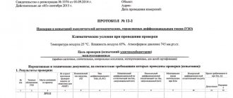
Based on the above, a protocol is formed:
As you can see, the main point in the protocol is the third point. As for the procedure for drawing up a test report in general, read the article TEST PROTOCOL FOR ELECTRICAL LABORATORY.
That's all for today. I wish you success!