Home > Theory > Capacitance
Capacitance refers to the special nature of resistance to alternating current observed in circuits with electrical capacitance. In this case, the capacitance of the capacitor depends not only on the elements included in the circuit, but also on the parameters of the current flowing in it (see the figure below).
Dependence of capacitance on frequency
We also note that the capacitor belongs to the category of reactive elements, the loss of energy on which does not occur in the alternating current circuit.
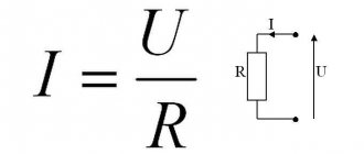
Capacitance formula
In order to determine the capacitance in a particular circuit, you will need to identify the following parameters:
- Frequency of alternating current flowing in the circuit;
- Nominal capacitance value of the capacitor;
- The presence of other radio elements in the circuit.
After all the above factors are taken into account, it will be possible to determine the capacitance of the capacitor using the following formula:
Xс=1/ ω C.
This formula indicates the inversely proportional dependence of resistance on the value of capacitance and frequency of the supply voltage.
Due to this nature of its change, capacitors can operate in the following frequency-dependent circuits:
- Integral and differential devices;
- Resonant circuits of various classes;
- Special filter elements.
Let's add to this the possibility of using capacitors as damping elements in an alternating current circuit loaded on powerful (power) units.
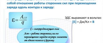
Capacitance
The use of capacitance in a DC circuit is familiar to every electronics engineer. In this case, the work of the part is described by relatively simple physical laws. Things are somewhat more complicated with alternating current, because with this use of capacitance it becomes necessary to take into account reactance.
Vector representation of capacity
Reactance
To get a clearer idea of what capacitance is, you can use the vector representation of the processes occurring in the capacitor.
Vector representation
After studying the diagram, you can notice that the current in the capacitor circuit changes phase ahead of the voltage by 90 degrees. From the nature of the interaction of basic electrical quantities, it is concluded that the capacitor resists changes in voltage across it.
The larger the capacitance, the slower it is recharged to full voltage (and the lower the capacitance of a given element). This conclusion completely coincides with the formula given earlier.
Additional Information. When examining inductances connected to alternating current circuits, the opposite pattern is discovered when the current, on the contrary, lags in phase with voltage changes.
Note that in both cases, the observed differences in the phase parameters indicate the reactive nature of the resistance of these elements.
Capacitor in an alternating current circuit. Capacitance of a capacitor.
We know that a capacitor does not allow direct current to pass through itself. Therefore, in an electrical circuit in which a capacitor is connected in series with the current source, direct current cannot flow.
behaves completely differently in an alternating current circuit (Fig. 1, a).
Figure 1. Comparison of a capacitor in an alternating current circuit with a spring acted upon by an external force.
During the first quarter of the period, when the alternating EMF increases, the capacitor is charged, and therefore a charging electric current i , the strength of which will be greatest at the beginning, when the capacitor is not charged. As the charge approaches the end, the charging current will decrease. The charging of the capacitor ends and the charging current stops at the moment when the alternating EMF stops increasing, having reached its amplitude value. This moment corresponds to the end of the first quarter of the period.
After this, the alternating EMF begins to decrease, at the same time the capacitor begins to discharge. Consequently, during the second quarter of the period a discharge current will flow through the circuit. Since the decrease in EMF occurs slowly at first, and then faster and faster, the strength of the discharge current, having a small value at the beginning of the second quarter of the period, will gradually increase.
So, by the end of the second quarter of the period, the capacitor will be discharged, the EMF will be equal to zero, and the current in the circuit will reach its maximum amplitude value.
With the beginning of the third quarter of the period, the EMF, having changed its direction, will begin to increase again, and the capacitor will begin to charge again. The capacitor will now charge in the opposite direction, corresponding to the changed direction of the EMF. Therefore, the direction of the charging current during the third quarter of the period will coincide with the direction of the discharge current in the second quarter, i.e., when moving from the second quarter of the period to the third, the current in the circuit will not change its direction.
Initially, while the capacitor is not charged, the charging current is the greatest. As the charge on the capacitor increases, the charging current will decrease. The charging of the capacitor will end and the charging current will stop at the end of the third quarter of the period, when the EMF reaches its amplitude value and its increase stops.
Capacitance
Units
A capacitor, as the owner of an electrical capacity, resembles a car battery in its performance. But, unlike a battery, the capacitive charge on it does not last long, which is explained by the presence of leaks in the dielectric and partial discharge through the environment.
In this case, the capacity (like that of a battery) determines the storage properties of the capacitor or its ability to retain energy between the plates.
Note! In the SI system, this indicator is measured in Farads, which are a very large unit of measurement.
In practice, smaller units of capacity measurement are most often used, namely:
- Picofarads, corresponding to 10-12 Farads (F);
- Nanofarads equal to 10-9F;
- Microfarads (µF), which are 10-6 of a Farad.
All these units for multiplicity are denoted as “pF”, “nF” and “mF”, respectively.
Example of capacitance calculation
Sometimes capacitors are installed in voltage suppression circuits in order to obtain lower voltage values (instead of step-down transformers).
Important! This method of obtaining the required voltages is considered not only very simple, but also the most dangerous, since inductive decoupling from high potential does not exist here.
But if you handle such a converter carefully, it will be quite possible to assemble it yourself. When calculating the required capacity, it is usually based on the following considerations:
- A capacitor connected in series with a load is characterized by impedance, an analogue of resistance for a capacitance;
- This indicator corresponds to a separate arm in the voltage divider, the second element of which is the load resistance;
- The ratio of the resistances of both arms is selected in such a way that the required voltage remains at the load (12 Volts, for example), and the entire remainder of 220 Volts is dissipated on the capacitor itself.
Additional Information. To improve the transient characteristics of the dividing chain, sometimes another resistor, called a discharge resistor, is connected in parallel with the capacitor.
Circuit for calculating capacitance
In our case, the following data is selected:
- Uin=220 Volts;
- Uout=12 Volts;
- Iload = 0.1 Ampere (current in the load is selected according to its passport).
Based on them, you can determine the value of the load resistance:
Rн=220/0.1=2200 Ohm or 2.2 Kom.
To calculate the value of the capacity at which the remaining 208 Volts should “fall”, the following indicators are used:
- Uс=208 Volts;
- Iс=0.1Amp;
- Fnetwork=50 Hz.
After this, you can calculate the ohmic resistance of the capacitor, sufficient for it to have 208 Volts:
Xc=Uс/Iс=208/0.1=2080.
The capacitance of the capacitor is obtained from the previously discussed relationship:
Xс=1/ ω C.
Based on this, we get:
C = 1/Xc2 π Fnetwork = 1/2080x6, 28x50 = 0.0000015311 Farads or 1.5 µF.
Resistance Rtime is selected to be approximately 10 Kom or more.
Capacitance
Capacitive, or reactive, resistance fundamentally depends on the frequency of the voltage. This relationship is clearly visible in the graph below. The higher the frequency, the lower the reactance. This is obvious from the above formula. The variable f (frequency) is in the denominator. Therefore, as it increases, Xc will decrease.
Properties of containers
Total resistance
When several capacitors are connected in parallel, their capacitances are added together. In this case, the total capacitance (according to the formulas discussed above) decreases. If all capacitor elements are connected in a series chain, their total capacitance is calculated as the inverse values of each component.
The capacitance of series-connected elements in this case, on the contrary, increases. In conclusion, we note that this nature of the change in capacitance and impedance is explained by the properties of the capacitor, which is capable of accumulating charge on its plates.
Capacitance of a capacitor
Capacitors are among the most common elements used in various electronic circuits. They are divided into types that have characteristic features, parameters and individual properties. The simplest capacitor consists of two metal plates - electrodes, separated by a dielectric layer. Each of them has its own terminal through which the connection to the electrical circuit is made.
Capacitance can be classified as reactive, which does not cause irreversible energy losses. The capacitor is charged to the voltage level supplied by the power source.
There are qualities unique to capacitors. For example, they do not allow direct current to pass through them at all, although they are charged by it. After the container is fully charged, the current flow stops completely, and the internal resistance of the device takes on an infinitely high value.
In a completely different way, the capacitor is affected by alternating current, which flows quite freely through the capacitance. This condition is explained by the constant processes of charging and discharging the element. In this case, not only the active resistance of the conductors acts, but also the capacitive reactance of the capacitor itself, which arises precisely as a result of its constant charging and discharging.
The electrical parameters and properties of capacitors may vary depending on various factors. First of all, they depend on the size and shape of the product, as well as on the type of dielectric. In different types of devices, the dielectric can be paper, air, plastic, glass, mica, ceramics and other materials. Electrolytic capacitors use aluminum electrolyte and tantalum electrolyte, which provides them with increased capacity.
Properties of containers
The main property is their ability to accumulate and release electrical charge. Both of these processes do not occur instantly, but over a very definite period that can be calculated. This property is used to create various timing RC circuits. If you charge a capacitor to a certain value, then the time it takes to discharge through resistor R will depend on the capacitance C.
Another common property of capacitors is their ability to limit alternating current. It is caused by the reagent of these elements. The capacitance included in the alternating current circuit limits it to the value I = 2pfCU. Here U is the voltage of the power source.
Additional Information. A capacitance connected in parallel with a coil having an inductive reactance is called an oscillatory circuit. This circuit has a high oscillation amplitude at the resonant frequency. It is used to select from the many surrounding radio signals exactly the one for which you want to tune the reception.
Resistance is one of the characteristics of a capacitor connected to an alternating current circuit. Understanding the processes occurring with this element in such circuits significantly expands the scope of its use. The reactance of capacitors is taken into account both in simple household electrical appliances and in complex computer technology.
Example of capacitance calculation
For the calculation you will need most of the listed physical quantities. They are indicated in the diagram and have the following meanings as an example:
- frequency f = 50 Hz (typical household network);
- capacitance C = 33 nF = 0.000000033 F = 3.3 * 10-8 F;
The reagent will be calculated using the formula described above:
In this case, the resistance of the capacitor in the AC circuit is 96.5 kOhm. If we write down all the calculations, we get the following.
The formula itself is not difficult. However, to carry out calculations, knowledge of a school algebra course is required, i.e. ability to work with powers, fractions and other mathematical algorithms. In practice, it makes sense to cheat a little. To avoid complex calculations every time, you can use one of the online calculators from the Internet. Such resources allow you to make a complex calculation and find out some other parameters of the circuit.
Capacitive element
A capacitive element (consider the example of a capacitor) is a two-terminal network with a variable or constant capacitance value. A capacitor is a storage device for electrical charges. If you connect it to a power source, it will charge. If a source with a variable component is applied to it, it will charge when a positive half-cycle passes through it. When the direction of the half-cycle changes to a negative value, the capacitor will begin to recharge, that is, the energy that has accumulated in it will begin to counteract recharging. As a result, we get a voltage on the capacitor opposite to the source. As a result, I will lead U by some angle φ. Below is the result of modeling work on a C-R load C = 900 * 10 - 6 Fa, R = 0.5 Ohm, U source = 250 V, frequency f = 50 Hz.
Figure 2. Source operation on RC load
For container:
Where ω – cyclic frequency
— supply voltage frequency, Hz;
C is the capacitance of the capacitor;
Conclusion: the higher the capacitance C or frequency, the lower the resistance to alternating current will be.