When current flows through a homogeneous section of the circuit, the electric field does work. During the time Δt, a charge Δq = IΔt flows through the circuit. The electric field in a selected area does work
| ΔA = (φ1 – φ2)Δq = Δφ12IΔt = UIΔt, |
where U = Δφ12 – voltage. This work is called the work of electric current.
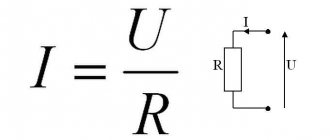
If both sides of the formula
| RI = U, |
expressing Ohm's law for a homogeneous section of a circuit with resistance R, multiply by IΔt, you get the relation
| RI 2 Δt = UIΔt = ΔA. |
This relationship expresses the law of conservation of energy for a homogeneous section of the chain.
The work ΔA of electric current I flowing through a stationary conductor with resistance R is converted into heat ΔQ released on the conductor.
| ΔQ = ΔA = RI 2 Δt. |
The law of converting the work of current into heat was established experimentally independently of each other by J. Joule and E. Lenz and is called the Joule–Lenz law.
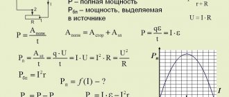
The power of the electric current is equal to the ratio of the current work ΔA to the time interval Δt during which this work was performed:
The work of an electric current in SI is expressed in joules (J), power - in watts (W).
Let us now consider a complete direct current circuit, consisting of a source with an electromotive force and internal resistance r and an external homogeneous section with resistance R. Ohm's law for the complete circuit is written as
| (R + r)I = ε. |
By multiplying both sides of this formula by Δq = IΔt, we obtain a relationship expressing the law of conservation of energy for a complete DC circuit:
| RI 2 Δt + rI 2 Δt = IΔt = ΔAst. |
The first term on the left side ΔQ = RI 2 Δt is the heat released in the external section of the circuit during the time Δt, the second term ΔQist = rI 2 Δt is the heat released inside the source during the same time.
The expression IΔt is equal to the work of external forces ΔAst acting inside the source.
When electric current flows through a closed circuit, the work of external forces ΔAst is converted into heat released in the external circuit (ΔQ) and inside the source (ΔQist).
| ΔQ + ΔQist = ΔAst = IΔt |
It should be noted that this ratio does not include the work of the electric field. When current flows through a closed circuit, the electric field does not do any work; therefore, heat is produced only by external forces acting inside the source. The role of the electric field is reduced to the redistribution of heat between different sections of the circuit.
The external circuit can be not only a conductor with resistance R, but also some device that consumes power, for example, a DC motor. In this case, R must be understood as the equivalent load resistance . The energy released in the external circuit can be partially or completely converted not only into heat, but also into other types of energy, for example, into mechanical work performed by an electric motor. Therefore, the question of using the energy of a current source is of great practical importance.
Ohm's law for a closed circuit
A closed (complete) electrical circuit consists of a current source and resistance.
The current source has an emf (
) and resistance (r), which is called
internal
.
EMF ( electromotive force
) is the work of external forces to move a positive charge along a closed circuit (the physical meaning is similar to voltage, potential). The total resistance of the circuit is R+r.
1) Voltage at the source terminals, and accordingly in the external circuit
, where quantity is
the voltage drop
inside the current source.
2) If the external resistance of the closed circuit is zero, then this mode of the current source is called a short circuit.
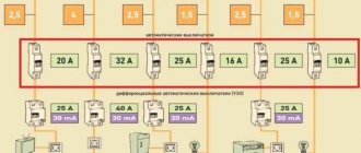
Power supply parameters
In practice, you often have to think about what the power of the current source should be, how many watts (W) or kilowatts (kW) are needed to ensure uninterrupted operation of the device. To understand the essence, you need to have an understanding of such concepts used in physics as:
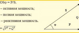
- total circuit energy;
- EMF and voltage;
- internal resistance of the power supply;
- losses within the individual entrepreneur;
- useful power.
Regardless of what kind of energy the source produces (mechanical, electrical, thermal), its power should be selected with a small margin (5-10%).
Total circuit energy
When a load is connected to the circuit, which will consume energy from a current source (IT), the current will do work. The energy released by all consumers and circuit elements included in the circuit (wires, electronic components, etc.) is called total energy. The energy source can be any: generator, battery, thermal boiler. The total energy value will be the sum of the energy spent by the source on losses and the amount spent on performing specific work.
EMF and voltage
What is the difference between these two concepts?
EMF is electromotive force, it is the voltage that external forces (chemical reaction, electromagnetic induction) create inside a current source (IT). EMF is the force of movement of electrical charges in IT.
For your information. It seems possible to measure the value of E (EMF) only in idle mode (idle). Connecting any load causes a loss of voltage inside the power supply.
Voltage (U) is a physical quantity representing the potential difference ϕ1 and ϕ2 at the output of the voltage source (VS).
Net power
The definition of the concept of total power is used not only in relation to electrical circuits. It is also applicable to electric motors, transformers and other devices capable of consuming both active and reactive components of energy.
EMF source
For the existence of direct current in a circuit, it is necessary to continuously separate electric charges, which, under the influence of Coulomb forces, tend to connect. This requires outside forces. EMF characterizes the action of these external forces. And this work itself is carried out inside the EMF sources. Electric charges inside EMF sources move against Coulomb forces under the influence of external forces.
Comparing the electric current with the flow of liquid in the pipes, we can say that the source works like a pump that supplies water from the lower reservoir to the upper one, from which it flows under the influence of gravity into the lower reservoir.
In everyday life, a “current source” is often inaccurately called any source of electrical voltage (battery, generator, socket), but in a strictly physical sense this is not so; moreover, voltage sources usually used in everyday life are much closer in their characteristics to an EMF source than to current source due to the presence of internal resistance.
Currently, many different EMF sources are produced - from small watch batteries to generators.
Inside the current source, charge separation occurs due to processes occurring inside the source, for example, chemical processes.
Galvanic cell
- a chemical current source based on the interaction of two metals and (or) their oxides in an electrolyte (batteries, accumulators).
Generators
- create current by expending mechanical energy.
Thermoelements
- use the energy of thermal motion of charged particles.
Photocells
- create current using light energy.
Relationship between useful power and efficiency
Efficiency factor (efficiency) is a dimensionless quantity, expressed numerically as a percentage. Efficiency is denoted by the letter η.
The formula looks like:
Where:
- A – useful work (energy);
- Q – energy expended.
As the efficiency increases in various engines, it is permissible to build the following line:
- electric motor – up to 98%;
- ICE – up to 40%;
- steam turbine – up to 30%.
In terms of power, efficiency is equal to the ratio of useful power to the total power delivered by the source. In any case, η ≤ 1.
Important! Efficiency and Ppol are not the same thing. In different work processes, they achieve the maximum of one or the other.
Obtaining maximum energy at the output of the IP
For your information. To increase the efficiency of cranes, injection pumps or aircraft engines, it is necessary to reduce the friction forces of mechanisms or air resistance. This is achieved by using a variety of lubricants, installing higher-class bearings (replacing sliding with rolling), changing the wing geometry, etc.
The maximum energy or power at the output of the IP can be achieved by matching the load resistance Rн and the internal resistance R0 of the IP. This means that Rн = R0. In this case, the efficiency is 50%. This is quite acceptable for low-current circuits and radio devices.
However, this option is not suitable for electrical installations. To avoid wasting large amounts of power, the operating mode of generators, rectifiers, transformers and electric motors is such that the efficiency is approaches 95% and above.
Achieving maximum efficiency
The formula for the efficiency of a current source is:
η = Pн/Ptotal = R/Rн+r,
Where:
- Pn – load power;
- Ptotal – total power;
- R is the total resistance of the circuit;
- Rн – load resistance;
- r – internal resistance of IT.
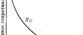
As can be seen from the graph shown in Fig. higher, the power Pn tends to zero as the current in the circuit decreases. The efficiency, in turn, will reach its maximum value when the circuit is open and the current is zero; if there is a short circuit in the circuit, it will become zero.
If we look at an elementary heat engine consisting of a piston and a cylinder, then its compression ratio is equal to the expansion ratio. Increasing the efficiency of such a motor is possible if:
- initially high parameters: pressure and temperature of the working fluid before expansion begins;
- bringing their values closer to environmental parameters at the end of expansion.
2. Dependence of power Pe, Pi, p on load resistance.
Consider the dependency
total, useful and internal
power from external resistance R
in the source circuit with EMF
E
and internal resistance
r
.
Full
the power developed by the source can be written as follows if we substitute the expression for current (1) into formula (5):
(18)
So the total power depends on the load resistance R.
It is greatest during a short circuit, when the load resistance goes to zero (9).
As the load resistance R
, the total power decreases, tending to zero at
R
.
Stands out at the external resistance
(19)
(20)
External
power
Рe is
part of the total power
Р
and its value depends on the resistance ratio
R /( R + r )
.
During a short circuit, the external power is zero. As resistance R
, it first increases.
At R r,
the external power tends to reach its full value.
But the useful power itself becomes small, since the total power decreases (see formula 18). At R
the external power tends to zero as does the total power.
What should be the load resistance to get the maximum
external (useful) power (19)?
Let's find the maximum of this function from the condition:
Solving this equation, we get R
max=
r
.
Thus, maximum power is released in the external circuit if its resistance is equal to the internal resistance of the current source.
Under this condition, the current in the circuit is equal to
E /2 r ,
i.e. half the short circuit current (8). Maximum useful power at this resistance
(21)
which coincides with what was obtained above (12).
Power released at the internal resistance of the source
(22)
At R
P i P
, and at
R = 0
it reaches the greatest value
P i nb = P nb = E 2 / r
.
When R = r,
the internal power is half the full power,
P i = P /2
.
At R r
it decreases almost in the same way as the total (18).
The dependence of efficiency on the resistance of the external part of the circuit is expressed as follows:
=
(23)
From the resulting formula it follows that the efficiency tends to zero as the load resistance approaches zero, and the efficiency tends to its highest value, equal to unity, as the load resistance increases to R
r
.
But the useful power decreases almost as much as 1/ R
(see formula 19).
Power R e
reaches its maximum value at
R max = r
, the efficiency is equal, according to formula (23),
=
r /( r + r ) = 1/2.
Thus,
the condition for obtaining maximum useful power does not coincide with the condition for obtaining the greatest efficiency.
The most important result of the consideration is the optimal matching of the source parameters with the nature of the load. Three areas can be distinguished here: 1) R
r
, 2)
R r
, 3)
R r
. The first case occurs where low power is required from the source for a long time, for example, in electronic watches and microcalculators. The size of such sources is small, the supply of electrical energy in them is small, it must be spent economically, so they must operate with high efficiency.
The second case is a short circuit in the load, in which all the power of the source is released in it and in the wires connecting the source to the load. This leads to excessive heating and is a fairly common cause of fires and fires. Therefore, a short circuit of high power current sources (dynamos, batteries, rectifiers) is extremely dangerous.
POWER DELIVERED IN THE EXTERNAL CIRCUIT
From formula (2) it is clear that with a short circuit (R®0) and with R® this power is zero. For all other finite values of R, the power P1> 0. Consequently, the function P1 has a maximum. The value of R corresponding to the maximum power can be obtained by differentiating P1 with respect to R and equating the first derivative to zero:
From formula (3), taking into account the fact that R and r are always positive, and E? 0, after simple algebraic transformations we get:
Consequently, the power released in the external circuit reaches its greatest value when the resistance of the external circuit is equal to the internal resistance of the current source.
In this case, the current strength in the circuit (5)
equal to half the short circuit current. In this case, the power released in the external circuit reaches its maximum value equal to
When the source is closed to an external resistance, then current flows inside the source and at the same time a certain amount of heat is released at the internal resistance of the source. The power expended to release this heat is equal to
Consequently, the total power released in the entire circuit is determined by the formula
Volt-ampere characteristics
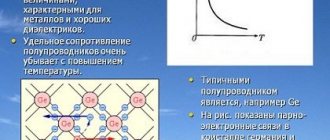
With its help, you can find out how the current changes when the voltage in the circuit increases or decreases. If it is built for a conductor, the dependence will be linear. This can be understood from Ohm's law, according to which the force is proportional to the applied potential difference. This type of graph is typical for metals. But at the same time, for semiconductors it will not be linear.
The thing is that such materials have special properties. A breakdown may occur in them - a phenomenon in which a sharp increase in current strength and a saturation process occur. In the latter case, the value of the electric current practically does not change with increasing voltage.
The dependence graph is constructed in a Cartesian coordinate system. The X axis represents voltage, and the Y axis represents current. You can study the characteristics for any circuit element yourself. To do this you will need to prepare:
- adjustable power supply;
- ammeter;
- voltmeter;
- element under study.
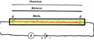
The circuit is assembled quite simply. A current meter (ammeter) is connected to the power supply, to the output of which a conductor is connected with one terminal. The second pole is connected to the free contact of the voltage source. The voltage meter is connected in parallel to the element being tested.
The experiment is as follows. Using the power supply, the voltage is changed, the value of which is read from the voltmeter. At the same time, data is written off from the ammeter. Then the coordinate axes of the current-voltage characteristics are drawn, on which the points of the corresponding quantities are plotted and connected by a smooth line. The drawn curve or straight line will display the real picture of the dependence of current on voltage for the element. Using the current-voltage characteristic, you can plot the dependence of power on current. To do this, you need to perform a calculation using the formula: P = I*U.
In practice, we often have to deal with alternating current. This is a phenomenon in which its strength changes over time. In this case, the current-voltage characteristic is not used, since the change in U occurs according to a certain law, most often sinusoidal, therefore, if you need to plot a graph of voltage versus time, you need to know the formula with which the function is described.