In electrical engineering, among the many definitions, concepts such as active, reactive and apparent power are often used. These parameters are directly related to the current and voltage in a closed electrical circuit when any consumers are turned on. To carry out calculations, various formulas are used, among which the main one is the product of voltage and current. First of all, this concerns constant voltage. However, in AC circuits, power is divided into several components noted above. The calculation of each of them is also carried out using formulas, thanks to which you can obtain accurate results.
Active, reactive and apparent power formulas
The main component is considered to be active power. It is a quantity characterizing the process of converting electrical energy into other types of energy. That is, in another way, it is the speed at which electricity is consumed. It is this value that is displayed on the electricity meter and paid by consumers. Active power is calculated using the formula : P = U x I x cosph.
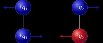
Unlike active energy, which refers to the energy that is directly consumed by electrical appliances and converted into other types of energy - thermal, light, mechanical, etc., reactive power is a kind of invisible assistant. With its participation, electromagnetic fields are created that are consumed by electric motors. First of all, it determines the nature of the load, and can not only be generated, but also consumed. Reactive power calculations are made using the formula : Q = U x I x sinф.
Total power is a quantity consisting of active and reactive components. It provides consumers with the necessary amount of electricity and keeps them in working condition. For its calculations, the formula is used: S = .
What does this mean
In alternating current networks, which absolutely the whole world uses today, there is no way to do without active and reactive powers - they are interdependent and even necessary. Active electricity refers to the voltage that is generated at thermal power plants, state district power plants, nuclear power plants, a mobile generator standing in a garage, etc. – it goes to the consumer (to factories, factories, to our home) and powers all electrical appliances from a network of ≈220-380 V. At the same time, the function of the reactive component of the total current is to wander aimlessly from the source to the consumer and back. So where does this seemingly useless substance come from?
If there is no foam on the beer, it means it does not meet the standards Source electrokaprizam.net
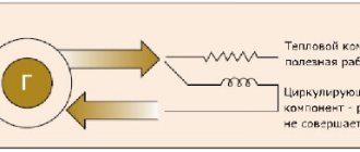
The thing is that in our homes, businesses and any other electrified objects there are devices with inductive coils (for example, we can take the stator of a motor), where magnetic fields constantly arise. That is, some of them rotate the rotor (armature), and some return back, and so on ad infinitum, as long as there is movement of active energy. This is well demonstrated by a mug of fresh beer: a person drinks only a small part of the foam with the liquid, and leaves the rest in the glass or blows it to the ground. But this very foam is a product of fermentation (induction), without which there will be no beer at all.
Now we can sum up the first conclusion in understanding the topic: if there is an inductive load (and it always exists), then a reactive current will certainly appear, consumed by induction, which itself creates it. That is, induction generates reactive power, then consumes it, generates it again, and so on constantly, but therein lies one problem. To move the reactive substance back and forth, active energy is needed, which is consumed due to the constant movement of electrons along the wires (heating of the wires).
Can we come to the conclusion that the active power of a generator is the complete opposite of reactive, seemingly useless power? But that's not true. Remember, the sisters are inseparable from each other, because they love each other, and no one will drink beer without foam, and the drink will not be able to ferment without it. The same can be said about reactive power - without it it is impossible to create magnetic fields, so this force will have to be taken into account. But then the brain convolutions of the inventors came into play, who decided to reduce the territorial space (not to drive back and forth along the wires) of this not entirely clear substance and produce it in close proximity to the object of consumption.
Any capacitor is a storage device and a source of reactive energy Source pikabu.ru
How to find active, reactive and apparent power
Active power refers to the energy that is irreversibly consumed by a source per unit of time for the consumer to perform some useful work. In the process of consumption, as already noted, it is converted into other types of energy.
In an alternating current circuit, the value of active power is defined as the average instantaneous power over a specified period of time. Consequently, the average value over this period will depend on the phase angle between current and voltage and will not be equal to zero, provided that active resistance is present in this section of the circuit. The last factor determines the name of active power. It is through active resistance that electricity is irreversibly converted into other types of energy.
When performing calculations of electrical circuits, the concept of reactive power is widely used. With its participation, processes such as the exchange of energy between sources and reactive elements of the circuit occur. This parameter will be numerically equal to the amplitude possessed by the variable component of the instantaneous power of the circuit.
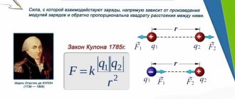
There is a certain dependence of reactive power on the sign of the angle φ shown in the figure. In this regard, it will have a positive or negative meaning. Unlike active power, which is measured in watts, reactive power is measured in var - reactive volt-amperes. The final value of reactive power in branched electrical circuits is the algebraic sum of the same powers for each element of the circuit, taking into account their individual characteristics.
The main component of total power is the maximum possible active power at a previously known current and voltage. In this case, cosф is equal to 1 when there is no phase shift between current and voltage. The total power also includes a reactive component, which is clearly seen from the formula presented above. The unit of measurement for this parameter is volt-ampere (VA).
Let the electricity receiver be connected to a source of sinusoidal voltage u(t) = Usin(ωt) and consume a sinusoidal current i(t) = I sin (ωt -φ), shifted in phase relative to the voltage by an angle φ. U and I are effective values. The value of instantaneous power at the receiver terminals is determined by the expression
| p(t) = u(t) ?i(t) = 2UI sin(ωt) sin (ωt -φ) = UI cos φ - UI cos (2ωt -φ) | (5.1) |
and is the sum of two quantities, one of which is constant in time, and the other pulsates with double frequency.
The average value p(t) over the period T is called active power and is completely determined by the first term of equation (5.1):
Active power characterizes the energy consumed irreversibly by the source per unit time to produce useful work by the consumer. The active energy consumed by electrical receivers is converted into other types of energy: mechanical, thermal, compressed air and gas energy, etc.
Average active power of power consumers
The active average power Pcm for groups of electrical receivers in the same operating mode for the most loaded circuit can be determined by the formula:
Where: ki is the utilization factor of the electrical receiver, Rnom is the rated power of the electrical receiver.
The ratio of the average active power of an electrical energy consumer (ki) or groups of such consumers (Ki) to their nominal values is called the utilization factor. It is calculated according to the formula:
n – number of consumers in the group.
The coefficient ki is related to the period of time for which the average power is calculated (shift, cycle, year).
For consumer groups with different operating modes, the weighted average utilization rate is determined. It can be calculated with sufficient accuracy using the formula:
Where: n is the number of subgroups of consumers with different operating modes included in this group;
Рсм – average power of the subgroup for the busiest shift;
— group active rated power;
For long-duty motors, the rated power is equal to the rated power Pnom = Ppassportn, for electric furnace transformers Pnom = Snomcosφnom (Snom is the total power of the device, cosφnom is the power factor of the welding transformer), for welding transformers (PV is the duration of switching on of the device, expressed in relative units).
Also, the average power can be determined based on the annual electricity consumption:
where RSG is the average annual load, which can be determined from the annual electricity consumption Wg:
ωud – electrical energy consumed per unit of output;
M – production output for the year;
TG – actual annual number of work of a workshop or enterprise;
α is the annual shift coefficient of energy use, determined from technological data.
This coefficient α takes into account different loads of individual shifts, load fluctuations caused by changing seasons (winter - summer), work performed on holidays and weekends, as well as irregular production. α can be characterized as the ratio of the annual energy consumption (by a workshop, enterprise, group of electrical receivers) to the annual electricity consumption for the busiest shift:
Below are approximate values of annual shift coefficients for energy use for various enterprises with three shift work schedules:
The number of hours of operation of power consumers of electrical energy depends on the technological process of work, as well as on the nature of production and can be calculated using the formula:
Where: m – non-working days in a year, n – number of shifts, t – shift duration, tpr – number of hours, annual, which takes into account the reduction in the duration of working days on holidays and weekends, kр – coefficient, which takes into account repair time and other downtime equipment (as a rule, kр is equal to 0.96 ÷ 0.98).
The annual number of operating hours of the enterprise can be determined from the table below (with the exception of workshops with a continuous operating cycle):
Accordingly, for enterprises with a continuous cycle of work (electrolysis and so on), the annual number of work increases.
Simple explanation with formulas
Active power (P)
In other words, active power can be called: actual, real, useful, real power. In a DC circuit, the power supplying a DC load is defined as the simple product of the voltage across the load and the current flowing, that is
because in a DC circuit there is no concept of phase angle between current and voltage. In other words, there is no power factor in a DC circuit.
But with sinusoidal signals, that is, in alternating current circuits, the situation is more complicated due to the presence of a phase difference between current and voltage. Therefore, the average power (active power) that actually powers the load is given by:
In an alternating current circuit, if it is purely active (resistive), the formula for power is the same as for direct current: P = U I.
Formulas for active power
P = UI - in DC circuits
P = UI cosθ - in single-phase AC circuits
P = √3 UL IL cosθ - in three-phase AC circuits
P = √ (S 2 – Q 2 ) or
P =√ (VA 2 – var 2) or
Active power = √ (Apparent power 2 – Reactive power 2) or
kW = √ (kVA 2 – kvar 2)
Reactive power (Q)
It could also be called useless or wattless power.
Power that constantly flows back and forth between the source and the load is known as reactive (Q).
Reactive power is power that is consumed and then returned by the load due to its reactive properties. The unit of active power is the watt, 1 W = 1 V x 1 A. Reactive power energy is first stored and then released as a magnetic field or electric field in the case of an inductor or a capacitor respectively.
Reactive power is defined as
and can be positive (+Ue) for an inductive load and negative (-Ue) for a capacitive load.
The unit of reactive power is the reactive volt-ampere (var): 1 var = 1 V x 1 A. In simple terms, a unit of reactive power defines the magnitude of the magnetic or electric field produced by 1 V x 1 A.
Definition and formula of useful power
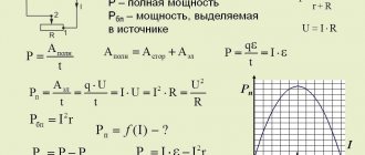
It is worth considering the concept of useful power and the formula using the example of an electrical circuit. The power that the power source (PS), in particular current, develops in a closed circuit will be the total power.
The circuit includes: a current source with EMF (E), an external circuit with a load R and an internal circuit of a power supply whose resistance is R0. The formula for total (total) power is:
Here I is the value of the current passing through the circuit (A), and E is the value of the emf (B).
Attention! The voltage drop in each section will be equal to U and U0, respectively.
So the formula will take the form:
Ptotal = E*I = (U + U0) *I = U*I + U0*I.
It can be seen that the value of the product U*I is equal to the power supplied by the source to the load and corresponds to the useful power Ppol.
The value equal to the product U0*I corresponds to the power that is lost inside the power supply for heating and overcoming the internal resistance R0. This is the power loss P0.
The values substituted into the formula show that the sum of useful and lost power makes up the total power of the IP:
Important! When operating any apparatus (mechanical or electrical), the useful power will be that which remains to perform the required work after overcoming the factors causing losses (heating, friction, counteracting forces).
Formulas for reactive power
Reactive power = √ (Apparent power 2 – Active power 2)
kvar = √ (kVA 2 – kW 2)
Apparent power (S)
Apparent power is the product of voltage and current, ignoring the phase angle between them. All power in the AC network (dissipated and absorbed/returned) is total power.
The combination of reactive and active power is called apparent power. The product of the effective voltage value and the effective current value in an alternating current circuit is called apparent power.
It is the product of voltage and current values without taking into account the phase angle. The unit of apparent power (S) is VA, 1 VA = 1 V x 1 A. If the circuit is purely active, the apparent power is equal to the active power, and in an inductive or capacitive circuit (if there is reactance), the apparent power is greater than the active power.
Condition for obtaining the greatest useful power (power in load)
The electric current develops the greatest useful power (power at the load) if the load resistance is equal to the resistance of the current source.
This maximum power is equal to half of the total power (50%) developed by the current source in the entire circuit.
Half of the power is developed at the load and half is developed at the internal resistance of the current source.
If we reduce the load resistance, then the power developed at the load will decrease and the power developed at the internal resistance of the current source will increase.
If the load resistance is zero, then the current in the circuit will be maximum, this is a short circuit (short circuit) mode . Almost all the power will be developed at the internal resistance of the current source. This mode is dangerous for the current source and also for the entire circuit.
If we increase the load resistance, the current in the circuit will decrease, and the power on the load will also decrease. If the load resistance is very high, there will be no current in the circuit at all. This resistance is called infinitely large. If the circuit is open, its resistance is infinitely large. This mode is called idle mode.
Thus, in modes close to a short circuit and no-load, the useful power is small in the first case due to the low voltage, and in the second due to the low current.
Power calculator – calculation by current, voltage, resistance
Using the power calculator , you can independently calculate power by current and voltage for single-phase (220 V) and three-phase networks (380 V). The program also calculates power through resistance and voltage, or through current and resistance according to Ohm's law. The cos φ value is taken according to the instructions in the technical data sheet of the device, the average values of the tables below, or calculated independently using formulas. We recommend not changing the coefficient unless necessary and leaving it at 0.95. To get the calculation result, click the “ Calculate ” button.
What formula is used to calculate
Calculation of current strength by power and voltage in a DC network
To calculate the force I (current), the value U (voltage) must be divided by the value of resistance.
Current calculation by power and voltage:
Measured in amperes.
For such a case, electrical P (active power) can be calculated as the product of the electrical force I by the value U.
Formula for calculating power by current and voltage:
All components in these two formulas are characteristic of direct electric current and are called active.
Based on these two formulas, we can also derive two more formulas by which we can recognize P:
Single-phase loads
In single-phase alternating current networks, it is necessary to calculate separately for P and Q loads, then they must be added using vector calculus.
In scalar form it will look like this:
As a result, the calculation of P, Q, S looks like a right triangle. The two legs of this triangle represent the P and Q components, and the hypotenuse is their algebraic sum.
S is measured in volt-amperes (VA), Q is measured in volt-ampere-reactive (VAr), P is measured in watts (W).
Knowing the sizes of the legs for triangles, you can calculate the power factor (cos φ). How to do this is shown in the triangle image.
Calculation in a three-phase network
Alternating I (current) differs from constant in all respects, especially the presence of several phases. Calculation of P in a three-phase load is necessary to correctly determine the characteristics of the connected load. Three-phase networks are widely used due to ease of use and low material costs.
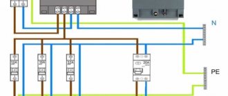
Three-phase circuits can be connected in two ways - star and delta. In all diagrams, the phases are designated by the symbols A, B, C. The neutral wire is designated by the symbol N.
When connected by a star, two types of U (voltage) are distinguished - phase and linear. Phase U is defined as the U between phase and neutral. Linear U is defined as U between two phases.
These two U are related by the relation:
Linear and phase electric currents when connected by a star are equal to each other: IЛ = IФ
Calculation form S for star connection:
S = SA + SB + SC = 3 × U × I
P = 3 × Uph × Iph × cos φ
Q = √3 × Uph × Iph × sin φ
.
When connected by a triangle, phase and linear U are equal to each other: UЛ = UФ
Linear I when connected by a triangle is determined by the formula:
Formulas for the power of electric current when connected by a triangle:
- S = 3 × Sph = √3 × Uph × Iph;
- P = √3 × Uph × Iph × cosφ;
- Q = √3 × Uph × Iph × sinφ.
Average P in active load
In electrical networks, P is measured using a special device - a wattmeter. Connection diagrams depend on the method of connecting the load.
With a symmetrical load, P is measured in one phase, and the result obtained is multiplied by three. In the case of an unbalanced load, three instruments will be required for measurement.
Total power and its components
Electrical power (P) in physics is a measure that shows how quickly the transformation or transfer of electricity occurs. The unit of measurement is watt (W, W). The value of P depends on the voltage (U) and current (I) in the closed circuit.
For direct current, the load consumed by P is the result of the product of current and voltage:
Attention! In this case, the values of both electrical characteristics are constant, which means that at every second of time their values are instantaneous.
The formula changes form if there is a source of electromotive force E (EMF) in the circuit:
For circuits where the current changes its values periodically along a sinusoid, this formula is not suitable. It is necessary to calculate P based on its instantaneous values in the time interval.
The total power S in its value corresponds to the expression:
Where:
- U – potential difference at the terminals, (V);
- I – current, (A).
To designate S, use the non-systemic unit B*A (V*A).
Loads included in variable current circuits can be:
- active;
- reactive: capacitive or inductive.
Active load (AH)
A similar load is the elements of devices that have active resistance. The working part of such devices heats up when electricity passes through them.
The current passing through the load does work, which is spent on heating and releasing thermal energy. How is this load measured? It is measured in ohms (ohms).
Examples of AN include: iron, electric stove, hair dryer coils, lamp filament, resistive resistance.
For your information. AN behaves the same way both with constant and with time-varying current.
Capacitive load
Devices that can store energy in an electric field and create recirculation (full or partial return) of power are called capacitive loads. A capacitive load (EC) at an alternating voltage, passing current, shifts its phase forward by 900.