Announcement:
Electric networks 0.4 kV and substations 6 (10) kV/0.4 kV in reactive power compensation calculations.
Calculation of reactive power compensation in 0.4 kV electrical networks. How to calculate the power of an installation for an electrical network of 0.4 kV. All electrical networks of 0.4 kV objects, based on the balance sheet boundary, usually determined by the presence or absence of their own 6/10 kV loads, can be divided into 6 (10) kV/0.4 kV substations and TPs connected on the low voltage side, which determines choice of method, methodology for calculating reactive power compensation and choice of power factor correction settings. So, for networks with:
- at 6 (10) kV/0.4 kV substations with a small volume of non-linear loads, compensation on the higher voltage side may be advisable;
- 6/10 kV loads, it must be taken into account that for these loads reactive power must be transmitted from the 6 (10) kV network, i.e. When integrating power factor correction devices on the low voltage side of a 6/10 kV transformer substation, it is necessary to use an individual or group compensation method.
Calculation of reactive power compensation in 0.4 kV electrical networks
When calculating reactive power compensation in 0.4 kV electrical networks, it is necessary to take into account that:
- the real power generated by a compensation installation based on capacitor banks depends on the rated network voltage Un and the voltage at the installation connection point Uin - Qph = (Un/Uin)²*Qpasp, where Qpasp is the nameplate rated power of the installation. For a 0.4 kV network Un = Uin – 1, for 6/10 kV networks Un/Uin = 0.95;
- if there are synchronous motors and/or long overhead lines in the electrical network of the facility, the permissible design power of generation by the installation of KRM, UKRMI, UKM must be reduced when integrating on the side: - voltage 0.4 kV on Qsd - power generated by synchronous motors in the network 0.4 kV (Qsd = α*Qн, where α is the rated (or reference) limit value of the motor overload for reactive power, Qн is the rated reactive power); - voltage 6/10 kV at (0.7*Qsd + Ql), where Ql is the reactive power generated by the overhead (or cable) line, which is equal to U²*Qу*L (U is the rated network voltage, Qу is the specific power of 1 km of cable / overhead line, L – line length);
- power factor correction by integrating KRM, UKRM, UKM, etc. installations is not performed in a 0.4 kV network at the design power of the installation
- the selection of capacitors for installation, a battery or an individual compensation circuit cannot be made only based on the ratio of the total power of nonlinear loads to the power of transformers - a technically competent selection of capacitors is made according to the nature of the loads, the operating mode of the equipment, the intensity of clogging of the network with current harmonics, operating conditions, etc. based on an energy audit and only by specialized specialists who manufacture reactive power compensation installations;
- any calculation calculator on the websites of trading companies and installation manufacturers is indicative, and online calculations, including the calculation of a transformer, installations, can be completely incorrect if: - the calculation calculator or online calculations are based on limited information, for example, according to active and reactive energy only during peak hours, in one of the seasons, without loading characteristics, operating mode, etc.; — the calculation calculator or online calculations initially contain incorrect (not formalized or technically justified) methods;
- a calculation calculator or online calculations, at best, give an after-the-fact idea of the need for compensation, but do not allow one to determine a cost-effective method and means of power factor correction, including the possibility of integrating relatively inexpensive unregulated units or capacitor banks, the presence or absence of the need to use active harmonic filters, etc.
Selecting a reactive power compensator
Installation power and type of power steering system
At the first stage, it is necessary to determine the power of the installations and the type of reactive power compensation system:
- individual;
- group;
- centralized;
- combined.
You can familiarize yourself in detail with the types of reactive power compensation systems in our article. Read more…
The most common PFC system is a combined compensation scheme.
Large consumers are compensated using individual compensators. In such a system, the power of the compensators is selected so that when the reactive power of the consumer fluctuates, cosφ always remains inductive, that is, there is no phenomenon of overcompensation. Small consumers with variable reactive power and residual deficit power of large consumers are compensated by a centralized capacitor installation.
Type of compensating installation: automatic and non-automatic
Non-automatic installation is the cheapest option for a capacitor installation. The power of the installation is not adjustable. This type is recommended for individual compensation of individual consumers. It can also be used in group compensation, where reactive power fluctuations are insignificant.
In cases where the installation contains more than one capacitor bank, it is possible to organize manual control of the installation’s power (manual switching on of steps). It must be taken into account that when the capacitor banks are disconnected, an electrical charge remains, and re-starting the stage is possible only after a long pause, which will ensure that the charge drains.
For centralized and group compensation, when reactive power constantly changes over time, automatic settings . By measuring the instantaneous values of voltage and current of the electrical network, the controller monitors the active and reactive components of power. Based on these measurements, the phase shift between current and voltage is calculated, the resulting value is compared with a predetermined cosine value φ. Depending on the actual deviation of the power factor, the controller issues a command to control the stages of the capacitor banks. The automatically executed sequence of connecting capacitors provides for a step-by-step approach to the optimum, correct loading and alternation of capacitors in order to ensure their uniform wear and increase their lifespan.
Harmonic composition of voltages and currents: selection of installation type
In networks where nonlinear voltage and current distortions are small, it is possible to use compensating installations. To determine the level of nonlinear distortion, the so-called total nonlinear distortion coefficient of voltage (THD U) and current (THD I) is used.
The following coefficients are considered acceptable for applying compensation settings: THD I - no more than 10%; THD U - no more than 3%. The use of compensating installations in networks with a high coefficient of nonlinear distortion leads to rapid failure of the installation as a result of swelling and explosions of the capacitor banks included in the device.
For networks with high nonlinear distortions, filter-compensating installations are used. A reactor (three-phase inductor) is placed in series with each capacitor so that the capacitor-inductor system is inductive at critical frequencies, and capacitive at the fundamental frequency of 50 Hz. To achieve this, the capacitor-inductor system must have a resonant frequency below the lowest harmonic frequency present in the network.
Selecting the switching part of the installation
Contactor installations are intended for use in networks with constant loads and with variable loads with a low rate of change (machine equipment, pumping, ventilation, etc.). Due to design features, the possible switching speed of cascades is once every 3-5 minutes.
Dynamic (thyristor) installations are intended for use in networks with rapidly changing loads (welding production, electric arc furnaces, etc.). Due to design features, the possible switching speed of cascades is up to 10 times per second.
Hybrid installations combine both cascade and thyristor modules. Contactor cascades achieve constant power. The change in power is compensated by thyristor modules.
Recommendations
For effective operation, the reactive power compensation installation (RPC), like any technological equipment, must be correctly selected and configured.
At the design stage, a preliminary survey of the quality of the electrical network is carried out, after which a set of measures is developed to improve quality, reduce energy consumption and associated costs. At this stage we offer:
- feasibility study of investments in equipment and measures to improve energy efficiency, energy saving and improve the quality of the power grid;
- development of UKRM, and selection of its installation location (local, group or centralized) according to your individual requirements.
Do you need to develop your own solution?
Send us primary information on the project: the scope of the company’s activities, possible problems in energy management, etc. We will measure and analyze network parameters and, based on the results, make a proposal for the implementation of both ready-made and customized solutions to improve power quality.
Order a project
How to calculate the power of a compensation installation for a 0.4 kV electrical network
The optimal data package for calculating reactive power compensation in 0.4 kV electrical networks includes limit values of active and reactive power during hours of maximum and minimum load, which are determined by:
- according to energy meter readings, annual daily consumption schedules;
- using the calculation method based on the average annual demand coefficient according to the passport (reference) data of equipment and formulas: Pmax = ∑Рnom*n*Ks, where Pnom is the rated power of a load of one type (machine, engine), n is the number of loads, Ks is the demand coefficient from table 1.6 for the equipment of departments/shops of reference book 1 /footnote 1 at the end of the article/ or determined by the utilization coefficient Ki of standard equipment (Table 1.9 of the reference book /footnote 1 at the end of the article/) and the dependence of Kc on Ki below;
Table.
Table. Dependence of Ks on Ki.
| Ki | 0,4 | 0,5 | 0,6 | 0,7 | 0,8 | 0,9 |
| KS | 0,5 | 0,6 | 0,65-0,70 | 0,75-0,80 | 0,85-0,90 | 0,92-0,95 |
- Qmax = Pmax*∑tg(φ)n/n, where tg(φ)n is the reactive power factor of a load of one type (or tg(arccos(φ)) with a known load power factor - Table 1.6 - 1.9 of reference book 1), n – number of loads of one type;
- Qmin is taken according to a typical load schedule for an enterprise during hours of minimum active load as a percentage or fraction of Qmax (0.5 – 0.6) - average Qmin = 0.55*Qmax.
Calculation and selection of compensating device
Power supply to the mechanical shop of an engineering plant Read more: Two three-phase wattmeters or one wattmeter with a switch that changes P and Q at some point in time determines the value
2.2 Calculation and selection of compensating device
The transfer of a significant amount of reactive power from the power system to consumers is irrational for the following reasons: additional losses of active power and energy occur in all elements of the power supply system, due to the loading of their reactive power, and additional voltage losses in the power supply networks. The introduction of a reactive power source leads to a reduction in losses during the period of maximum load by an average of 0.081 kW/kvar. Currently, the compensation rate during the peak period is 0.25 kvar/kW, which is significantly less than the economically feasible compensation of 0.6 kvar/kW.
When choosing reactive power compensation means in power supply systems of industrial enterprises, it is necessary to distinguish two groups of industrial networks based on functional characteristics, depending on the composition of their loads: the first group is general purpose networks (networks with a positive sequence mode of the fundamental frequency of 50 Hz); the second group is networks with specific nonlinear, asymmetrical and sharply variable loads.
The largest total reactive load of the enterprise, taken to determine the power of the compensating installation, is equal to: QM1=KHCQP, where KHC is a coefficient that takes into account the time discrepancies between the highest active load of the power system and the reactive load of the enterprise.
Based on the input reactive power QE1, the total power of the compensating device of the enterprise is determined, and according to the purpose of QE2, the regulated part of the compensating device is determined.
The total power of the compensating device QE1 is determined by the balance of reactive power at the boundary of the electrical interface of the enterprise and the power system during the period of the highest active load of the power system: QK1=QM1+QE2. For industrial enterprises with a connected total power of transformers less than 750 kV*A, the power value of the compensating device QE1 is set by the power system and is mandatory when implementing the enterprise's power supply project.
In agreement with the power system that issued the technical conditions for connecting consumers, it is allowed to accept a greater total power of the compensating device compared to QE1, if this reduces the reduced costs of the enterprise’s power supply system as a whole.
Reactive power compensation means in general purpose networks are capacitor banks (low voltage - NBK and high voltage - VBK) and synchronous motors in networks with specific loads, in addition to the above means, power resonant filters (SRF), baluns and filter baluns, dynamic and static reactive power compensation with high-speed control systems (STC) and special high-speed synchronous compensators (SSC).
Reactive power compensation in general-purpose electrical networks with voltages up to 1000 V
Most reactive power consumers are connected to networks with voltages up to 1000 V at industrial enterprises. The power factor of the low voltage load does not exceed 0.8. Networks with a voltage of 380-660 V are electrically more distant from power sources, so the transfer of reactive power in low voltage networks requires an increase in cross-sections of wires and cables, an increase in the power of power transformers and is accompanied by losses of active and reactive power. Costs caused by these factors can be reduced or even eliminated if reactive power compensation is carried out directly in the low voltage network.
The sources of reactive power in the low voltage network are synchronous motors with a voltage of 380-660 V and capacitor banks. When solving the problem of reactive power compensation, it is necessary to establish the optimal relationship between low-voltage and high-voltage reactive power sources, taking into account the losses of electrical energy for the generation of reactive power by low-voltage and high-voltage sources, the losses of electrical energy for the transmission QMAX.T from the high voltage network to low voltage network and holding the transformer substation in case of loading them with reactive power.
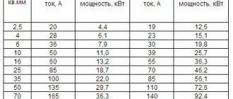
The selection of the optimal low voltage power of the capacitor bank is carried out simultaneously with the selection of the workshop transformer substation. The design power of the low voltage capacitor bank is rounded to the nearest standard power of the complete compensating devices. The main technical characteristics of an unregulated low voltage capacitor bank are given in the table, while those are regulated by current and voltage.
For each workshop transformer substation, the possibility of distributing the found PBC power in the workshop network is calculated. The criterion for the feasibility of such a solution is the reduction of reduced costs due to the unloading of the low voltage network from reactive power.
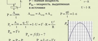
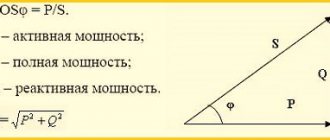
The essence of cos φ.
Current power factor at each time:
, (2. 
where and are respectively the active, apparent and reactive power at the moment of time, kW, kV*A, quar..
The active and reactive powers of enterprises change not only over long periods of time (days, months), but also during one production shift.
The value of the power factor at time ti is most accurately determined using a phase meter. In the absence of a phase meter, cos φ is determined in one of the following ways:
Power supply to the mechanical shop of an engineering plant Read more: Two three-phase wattmeters or one wattmeter with a switch that changes P and Q at some point in time determines the value
Information about the work “Power supply of the mechanical shop of a machine-building plant”
Section: Industry, production Number of characters with spaces: 37264 Number of tables: 5 Number of images: 20
Similar works
Design of a power supply system for a machine-building plant workshop
67198
28
3
... are influenced by such factors as the degree of responsibility of electrical receivers, their operating mode and placement on the workshop territory. Shop networks of industrial enterprises operate at voltages up to 1 kV (the most common voltage is 0.38 kV). When designing a power supply system, it is necessary to correctly establish the nature of the environment, which has a decisive influence on the degree ...
Design of a power supply system for a machine shop
125619
17
5
... or engine. · Local control is the control of the drive of a circuit breaker, disconnector and other equipment directly on site. · Automatic control – it is used in the power supply system of enterprises with high power consumption. Automatic control is carried out using VMU control computers. Information entering the VMU is processed and...
Development of a power supply system for a mechanical workshop
124039
16
9
..., then the installation of compensating devices at the substation is economically justified. 3.9 Main technical and economic indicators of the power supply system of the mechanical shop. The main technical and economic indicators of the power supply system of the workshop are given in Table 3.8. Table 3.8 – Main technical and economic indicators Indicator Quantitative value Number of industrial...
Design of power supply for a mechanical workshop
30331
4
0
... 280 A, three-pole, with 16 outgoing lines with fuses of the NPN-100 type. 2.4 Calculation of short circuit currents and testing of elements in a characteristic power supply line 2.4.1 General information about short circuits When designing solar power plants, not only normal, long-term operating modes of the power plant are taken into account, but also their emergency modes. One of the emergency modes is a short circuit. Short circuit...
How to calculate the power balance between 0.4 kV and 6 (10) kV networks.
The calculated values of active Рр and reactive Qр power are determined as Рр = Рmax + ΔРт and Qр = Qmax + ΔQт, where ΔРт and ΔQт power losses in transformers according to the passport data or approximately according to the formulas ΔРт = 0.02*Sр and ΔQт = 0.1*Sp, where total design power Sp = √(P²+Q²)
Set the specified according to the specifications or calculated input reactive powers QE1 and QE2, which will be transferred from the network of the electric grid company to the network of the facility in the modes of the highest and lowest active loads:
QE1 is taken according to the smaller value determined from the formulas QE1 = Qr – 0.7*Qsd and QE1 = α*Rr, where Qsd is the reactive power generated by synchronous motors (see above or in the absence of synchronous motors in the network Qsd = 0), α – calculated coefficient from the table below
Table.
Calculated coefficients α for power systems of different regions.
| Energy systems by region | Coefficient α value for 6-20 kV busbars at higher voltage | ||
| 35 kV | 110-150 kV | 200-330 kB | |
| North-West, Center, Middle Volga, South, Kazakhstan | 0,23 | 0,28 | 0,37 |
| Central Asia | 0,30 | 0,35 | 0,47 |
| Siberia | 0,24 | 0,29 | 0,40 |
| Ural | 0,27 | 0,31 | 0,42 |
| North Caucasus, Transcaucasia | 0,22 | 0,26 | 0,34 |
| East | 0,20 | 0,35 | 0,32 |
QE2 is set according to the larger limit value from the formulas QE2 = Qmin - (Qр - QE1) and QE2 = Qmin + Qk, where Qk is the reactive power generated by the operating installations if they are present (in the absence of Qk = 0 and QE2 = Qmin).
How to calculate the number and power of transformers.
The specific load density of transformers is determined by the calculated total power Sp and the area of the object F, namely σ = Sp/F
Threshold values of the rated power of transformers Sн are established based on the specific load density, taking into account the fact that:
- at σ ˂ 0.2 kVA/m², transformers with a power of up to 1000 kVA are appropriate;
- at σ ˂ 0.2-0.3 kVA/m², transformers with a capacity of 1600 kVA are appropriate;
- at σ > 0.3 kVA/m², transformers with a capacity of 1600 kVA or 2500 kVA are appropriate.
Table.
Recommended rated power of the transformer at different specific load densities.
| Specific load density σ | kVA | 0,05 | 0,08-0,14 | 0,15-0,2 | 0,21-0,3 | 0,3-0,35 |
| Rated power Snt | kVA | 400 | 630 | 1000 | 1600 | 2500 |
Find the number of transformers (rounded towards a larger integer value) Nt = Pmax/(Kz*Snt), where Kz is the load factor of the transformer, which is taken equal to:
- Kz = 0.65-0.7 with a predominance of category I loads for a two-transformer substation;
- Kz = 0.7-0.8 with a predominance of category II loads for single-transformer transformer substations and mutual redundancy on the low voltage side;
- Kz = 0.9-0.95 with loads of category II and the presence of a warehouse reserve, as well as with the predominance of loads of category III.