Incorrectly performed electrical work during home construction or renovation often results in accidents, fires, or electrical injuries. Therefore, immediately at the planning stage, it is necessary to use wiring that meets safety requirements.
In the article I show how to calculate the cable cross-section by power: a calculator and tables are attached. I supplement the information for beginners with pictures and diagrams explaining the basic electrical processes.
An experienced electrician may not read the explanations, but immediately open the online calculator through the contents section and make the necessary calculations in it.
What are the dangers of incorrectly installed electrical wiring: how hidden risks manifest themselves
Since the beginning of the summer season, a new neighbor brought his friend Andrei to me. He has a request: help resolve the issue with low voltage in his area. He is particularly concerned about the low levels in the garage where he has set up his electrical workshop.
Let's go have a look and check. Voltage is supplied to the input panel of a private house. My pocket multimeter showed 203 volts, which is generally acceptable for rural areas.
But then miracles began. On its large territory there are several outbuildings. They are connected in a daisy chain: one to the other. The garage is at the very end.
The total length of the highway exceeds one hundred meters. The connection was made with what was at hand: 1.5 mm square copper wire, and individual sections between buildings were powered even with 2.5 square meter aluminum strands.
This area has increased resistance. It creates a voltage drop at the entrance to the garage of up to 185 volts. And this is no longer enough for the normal operation of electric motors of various machines.
Andrey’s losses in the area from his house to his workshop amounted to 18 volts. He was going to buy a voltage stabilizer for the garage, and I explained to him that this could not be done for the following reasons:
- the stabilizer will raise the voltage level at its output and the power consumption of the machines will increase even more;
- This will further increase the load on the wiring.
In this situation, an additional voltage drop will occur at the input to the stabilizer, which will entail:
- disabling it from protection;
- or an emergency situation occurs in the wiring due to its overload and overheating.
Unnecessary voltage losses can only be eliminated by correct selection of the cross-section of the power cable, taking into account the transmitted power and its reliable installation.
Calculators for calculating the required conductor cross-section
When carrying out independent electrical installation work, the cleaners are likely to be faced with the problem of what cross-section of wire is needed in a particular section of apartment (household) wiring. This can be determined in several ways, or even simply found out by consulting an experienced electrician.
Calculators for calculating the required conductor cross-section
Or you can make your own calculation, based on what exactly you plan to connect on the line being laid. This is not so difficult if you use the proposed calculators to calculate the required conductor cross-section. The first of them is the main one, the second allows you to check and, if necessary, adjust.
Below we will give some explanations on working with calculators.
Calculator No. 1 - calculation of the required conductor cross-section
Go to calculations
Explanations for working with the first calculator
The calculation in this case is carried out based on the permissible current density. This parameter is set separately for copper and aluminum wires, separately for open and closed wiring. The main point is that with an acceptable current density (amps per mm² cross-section of the conductor), the conductor does not heat up to dangerous temperatures that can lead to melting of the insulation, with all the ensuing consequences.
So, to calculate in the appropriate fields of the calculator you should indicate:
- Type of planned wiring: copper or aluminum, open or closed. By the way, wires enclosed in cable channels, which seem to be located on the surface of the wall, still belong to closed wiring, since there is no normal heat sink there. Likewise with areas in cabinets or boxes.
- The voltage that will be applied to the line. By the way, in some cases it can be not only variable, but also constant.
- What temperature would be considered normal in the room? The fact is that the higher the initial temperature, the closer the threshold for the onset of insulation melting (90 degrees), and the less stress the wires should experience. So, for every 10 degrees above normal +20-25 ℃ (for example, dryer, dressing room, greenhouse), a reduction factor is introduced. All this will be taken into account in the calculation.
- Next, you need to indicate the power of the devices that, according to the plan, will be connected to this line. It is possible to enter up to 6 different loads.
Moreover, the last two also take into account reactive power. Some devices, equipped, for example, with powerful electric motors, in addition to the rated power consumption, also use reactive power. For such products, the total power is higher, and to determine it, a coefficient called cos φ , which is indicated in the device passport. In the event that reactive power is not used, cos φ remains equal to unity.
Any of the power fields can be left blank - then it will simply be excluded from the calculation.
- It is unlikely that all devices planned to be connected to the line will work simultaneously. But you still need to be prepared to a certain extent for such a situation. There is a so-called demand coefficient, which takes into account the probability of simultaneous load connection. It will be entered into the calculation based on the number of planned devices.
- Finally, when laying a line, it is sometimes useful to think about some reserve power for the future, for example, in case of expanding the “park” of your household appliances. The last field asks you to specify a safety factor - from 1.0 (everything remains unchanged) to 2.0, in increments of 0.1.
The result of the calculation is shown in square millimeters, and then reduced (rounded) up to the nearest standard wire cross-section.
Calculator No. 2 - checking the wire cross-section for voltage drop in the line
Go to calculations
Explanations for working with the second calculator
You should never forget that any wire itself has a resistance that, in accordance with Ohm's law, causes a certain voltage drop. This is especially sensitive on long lines. And if you plan to lay a long cable, say, to a workshop or to a remote kitchen, or even just make an extension cord for construction or gardening work, it would be useful to check this parameter.
According to existing rules, the voltage drop on the line should not exceed 5% of the nominal value.
To calculate you will need to indicate:
- Nominal line voltage.
- The load current for which the cable cross-section was selected. You just need to sum up the power of all devices that were taken into account in the previous calculator, and then divide the sum by the voltage.
- Next, the wiring material is indicated: copper or aluminum. This is necessary for inclusion in the algorithm for calculating resistivity values.
- The next data entry field is the length of the line being created in meters.
- Finally, the last point is the cross-section of the cable conductor. Important - this should not be the result of the previous calculator, but a rounded standard value.
After pressing the button, the answer is displayed.
- If the resulting voltage drop value is less than 5%, then you can continue installation with a cable of the specified cross-section without changing anything.
- If the value is more than 5%, then the cable cross-section should be increased by one step and the calculation done again. And so on until the result falls within 5%.
Choosing cables for home wiring is a responsible task!
In this matter, beginners traditionally make a very large number of mistakes, each of which can result in very serious, to say the least, consequences. about the nuances of choosing cables for home wiring in a separate detailed publication on our portal.
Principles for selecting cables based on current: what processes are taken into account
Wires and cables for home wiring are produced in a large assortment with different cross-sections of copper or aluminum cores. Their cross section is calculated using the formula for the area of a circle through the diameter, which can be easily determined with measuring instruments, for example, a micrometer.
Since they are designed to work under different operating conditions, they have different designs, each of which has its own name, for example, NYM, PUNP, PUNGP, VVG, VVGng, PVS and other designations.
The internal structure of any of them consists of metal cores and insulation. As an example, I show a picture of the VVGng cable.
Any conductor has electrical resistance. When current passes through it, heat is released, described by the Joule-Lenz law. It depends on the magnitude of the load, the time it occurs and the resistance of the conductor.
In this case heating occurs:
- metal core;
- insulation layer;
- environment surrounding the cable.
I propose to look into the third question in more detail.
How operating conditions affect the operation of wiring: features of open and closed installation
Please note that the environment surrounding the cable can remove heat, reducing heating, or increase its temperature by localizing the installation site with heat-insulating materials located in close proximity.
Therefore, wiring located in the open air, thanks to natural ventilation (moving heat up and cooled masses down), cools better than those hidden in pipes or inside building structures.
Insulating materials work well when heated to an acceptable temperature, and after it reaches critical values, they dry out, losing their dielectric properties. Then leakage currents are created through them, leading to accidents or fires.
Therefore, for each type of wire, temperatures of permissible heating have already been selected, taking into account the passage of long-term loads through them. Since resistance, according to Ohm’s law, already affects the magnitude of the current, the entire calculation is carried out based on it.
When using this technique, it is necessary to sum up all the loads that can pass through the core. For example, sockets connected by a cable can power several household appliances at the same time. This point should be taken into account when choosing the cross-section of the cable feeding them.
In order not to complicate this process with formulas, ready-made tables are used in practice. I give an excerpt from them, necessary for the home master.
The method for selecting cable cross-section for current is basic. He:
- based on numerous scientific experiments;
- laid down in the PUE to ensure reliable and safe operation of electrical equipment;
- allows you to optimally select the wiring cross-section at a price.
To ensure increased safety during operation, it is permissible to create a reserve area by using a cable with thicker cores. And installing it with a reduced cross-section is dangerous.
Cable cross-section
The cable cross-section is the cut area of the current-carrying core. If the cut of the core is round (as in most cases) and consists of one wire, then the area/section is determined by the formula for the area of a circle. If there are many wires in the core, then the cross-section will be the sum of the cross-sections of all the wires in this core.
The cross-sectional values are standardized in all countries, and the standards of the former CIS and Europe in this part completely coincide. In our country, the document that regulates this issue is the “Rules for the Construction of Electrical Installations” or briefly - PUE.
The cable cross-section is selected based on the loads using special tables called “Permissible current loads on the cable.” If you have no desire to understand these tables, then it is enough for you to know that it is advisable to use a copper cable with a cross-section of 1.5-2.5 mm² for sockets, and 1.0-1.5 mm² for lighting.
To introduce one phase into an ordinary 2-3 room apartment, 6.0 mm² is quite enough. All the same, your 40-80 m² will not fit larger equipment, even taking into account the electric stove.
Many electricians, in order to “estimate” the required cross-section, believe that 1mm² of copper wire can pass 10A of electric current through itself: accordingly, 2.5 mm² of copper can pass 25A, and 4.0 mm² - 40A, etc. If you analyze the cable cross-section selection table a little, you will see that this method is only suitable for estimation and only for cables with a cross-section no higher than 6.0 mm².
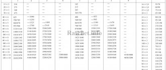
Below is an abbreviated table for selecting cable cross-sections up to 35 mm² depending on current loads. For your convenience, the total power of electrical equipment is given there for 1-phase (220V) and 3-phase (380V) consumption.
When laying the cable in a pipe (i.e. in any closed spaces), the possible current loads on the cable should be less than when laying it openly. This is due to the fact that the cable heats up during operation, and heat transfer in a wall or in the ground is much lower than in open space.
When the load is called in kW, we are talking about the total load. Those. for a single-phase consumer, the load will be indicated for one phase, and for a three-phase consumer - in total for all three. When the load value is named in amperes (A), we are always talking about the load on one core (or phase).
Load table for cable cross-section:
| Cable cross-section, mm² | Laid open | Installed in a pipe | ||||||||||
| copper | aluminum | copper | aluminum | |||||||||
| current, A | power, kWt | current, A | power, kWt | current, A | power, kWt | current, A | power, kWt | |||||
| 220V | 380V | 220V | 380V | 220V | 380V | 220V | 380V | |||||
| 0.5 | 11 | 2.4 | ||||||||||
| 0.75 | 15 | 3.3 | ||||||||||
| 1 | 17 | 3.7 | 6.4 | 14 | 3 | 5.3 | ||||||
| 1.5 | 23 | 5 | 8.7 | 15 | 3.3 | 5.7 | ||||||
| 2.5 | 30 | 6.6 | 11 | 24 | 5.2 | 9.1 | 21 | 4.6 | 7.9 | 16 | 3.5 | 6 |
| 4 | 41 | 9 | 15 | 32 | 7 | 12 | 27 | 5.9 | 10 | 21 | 4.6 | 7.9 |
| 6 | 50 | 11 | 19 | 39 | 8.5 | 14 | 34 | 7.4 | 12 | 26 | 5.7 | 9.8 |
| 10 | 80 | 17 | 30 | 60 | 13 | 22 | 50 | 11 | 19 | 38 | 8.3 | 14 |
| 16 | 100 | 22 | 38 | 75 | 16 | 28 | 80 | 17 | 30 | 55 | 12 | 20 |
| 25 | 140 | 30 | 53 | 105 | 23 | 39 | 100 | 22 | 38 | 65 | 14 | 24 |
| 35 | 170 | 37 | 64 | 130 | 28 | 49 | 135 | 29 | 51 | 75 | 16 | 28 |
To independently calculate the required cable cross-section, for example, for entry into a house, you can use a cable calculator or select the required cross-section from the table.
This table applies to cables and wires with rubber and plastic insulation. These are such widespread brands as: PVS, GDP, VPP, PPV, APPV, VVG. AVVG and a number of others. Paper-insulated cables have their own table, and non-insulated wires and buses have their own.
When calculating the cable cross-section, the specialist must also take into account the methods of laying the cable: in trays, in bundles, etc.
- In addition, the values from the tables on permissible current loads must be adjusted by the following reduction factors:
- correction factor corresponding to the cable cross-section and its location in the block;
- correction factor for ambient temperature;
- correction factor for cables laid in the ground;
- correction factor for different numbers of operating cables laid nearby.
How to calculate a cable based on load power in simple words
For most modern household appliances, the accompanying documentation provides information not about the load current, but about the amount of power consumption. These parameters of the electrical network are interconnected.
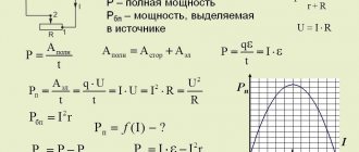
They can be easily recalculated using the well-known formulas contained in the electrician’s cheat sheet.
However, there is a simpler and more accessible way: a ready-made tabular form. It saves a person from mathematical calculations.
The same rule for adding the powers of all connected devices applies here, as before for the load current.
Let's look at an example. Three consumers with a load of 2, 1.5 and 1.0 kW can be simultaneously inserted into a socket group of three sockets connected in series. Add them up and we get 4.5 kilowatts.
Let's look at the table. For 220 volt wiring laid in an open way, it is enough to use copper with a cross-section of one and a half square or aluminum - 2.5. When choosing a closed installation method, you will need to increase the copper wire to 2.5 mm sq., and the aluminum wire to 4.0.
By the way: it is generally accepted to install wires with a cross-section of 2.5 millimeters square on any socket groups. Here there are additional requirements for their mechanical strength, which requires a margin of thickness.
This requirement is especially relevant for aluminum wiring, which has reduced mechanical strength. Numerous owners of apartments in old multi-storey buildings have been convinced of this more than once.
Creating a small reserve of cable cross-section in the future can save the owner from unforeseen problems when purchasing and connecting new, more powerful electrical equipment.
Input cable calculation
After calculating the total power of single-phase consumers, the corresponding current is calculated using the formula:
where P is the total power you calculated, W;
U – network voltage equal to 220 V;
cos (φ) – power factor, for household appliances is taken equal to unity;
Ki is the coefficient of load simultaneity, taking into account that your electrical appliances are unlikely to work at the same time. Its exact value is difficult to predict, so for calculations you can take Ki = 0.75.
For a three-phase load in a 380 V network, the current is calculated using the formula:
Now you can find out the cross-section of the input cable through which power will be supplied to the apartment or country house. To select it, you must use the table for calculating the cross-sections of cables with polyvinyl chloride and polymer insulation. Most products used for laying household electrical wiring have such insulation. For rubber insulation and cross-linked polyethylene, a different table is needed; it can be found in GOST 31996-2012.
| Cables with copper conductors | ||||
| Core cross-section, mm2 | Permissible current loads | |||
| Single-core | Stranded | |||
| On air | In the ground | On air | In the ground | |
| 1,5 | 22 | 30 | 21 | 27 |
| 2,5 | 30 | 39 | 27 | 36 |
| 4 | 39 | 50 | 36 | 47 |
| 6 | 50 | 62 | 46 | 59 |
| 10 | 68 | 83 | 63 | 79 |
| 16 | 89 | 107 | 84 | 102 |
| 25 | 121 | 137 | 112 | 133 |
| 35 | 147 | 163 | 137 | 158 |
| 50 | 179 | 194 | 167 | 187 |
| 70 | 226 | 237 | 211 | 231 |
| Cables with aluminum conductors | ||||
| Core cross-section, mm2 | Permissible current loads | |||
| Single-core | Stranded | |||
| On air | In the ground | On air | In the ground | |
| 2,5 | 22 | 30 | 21 | 28 |
| 4 | 30 | 39 | 29 | 37 |
| 6 | 37 | 48 | 37 | 44 |
| 10 | 50 | 63 | 50 | 59 |
| 16 | 68 | 82 | 67 | 77 |
| 25 | 92 | 106 | 87 | 102 |
| 35 | 113 | 127 | 106 | 123 |
| 50 | 139 | 150 | 126 | 143 |
| 70 | 176 | 184 | 161 | 178 |
| 95 | 217 | 221 | 197 | 214 |
In order to determine the permissible load on four-core and five-core cables, the data from the table must be multiplied by a factor of 0.93.
The use of aluminum wires for the installation of electrical wiring in buildings has been prohibited since 2001. But it is possible to supply power to the house with an aluminum cable if its cross-section is at least 16 mm2.
There are also restrictions on the minimum cross-section of cable lines.
| Cable lines | Minimum cross-section of cables with copper conductors, mm2 |
| Rosette groups | 2,5 |
| Lighting network groups | 1,5 |
| From floor panels to subscriber meter | 2,5 |
| Apartment power distribution lines | 4 |
Selecting cable cross-section by power and current: reference data table
This method incorporates the two calculation methods above. They are simply summarized in a general table.
It is convenient to use, having any information: on load current or power consumption, which allows you not to have to convert one value to another.
However, one parameter is hidden in all these tables, namely: a very long electrical circuit. It indirectly affects the calculation results. But read about this in the next subsection.
Why is it necessary to take into account the length of an extended electrical line in a private house?
All tables above take into account the final effect of electric current on heating the metal core. Its value practically does not change within the apartment, where the distance from the input panel to the end user rarely exceeds 15 meters.
However, we know that the electrical resistance of a wire affects the current, and with increasing distance it always increases in direct proportion to the ratio of resistivity to cross-sectional area.
Over long sections, additional voltage losses occur, and all this must be taken into account in accurate calculations, which is used in practice in the online calculator given in the next section.
By way of explanation, I will give an example of such an influence applied during the installation of precise VT voltage measuring circuits at my 330 kV substation, where losses should be minimal. They are fought with all available means.
These voltage transformers are located at the outdoor switchgear-330 kV. They are located at a distance of about 300-400 meters from the relay panels.
The secondary circuits are assembled in a cabinet. They are supplied to it from the output box located at the bottom of the base of the porcelain insulator via a short control cable with 1.5 mm square conductors.
You can estimate its length visually from the photograph. It does not exceed a few meters. The output cables of the voltage circuits laid to the panels of the relay room have an increased cross-section of conductors and exceed 16 mm square.
This can be clearly seen on the back of the relay panel input.
This was done in order to minimize voltage losses over such a long distance. They should not introduce an error greater than 0.5%.
On the panels themselves, the wiring is again done with 1.5 square meter cores. Short distances from the VT to its cabinet and in the relay room do not have a significant effect on losses.
With the example given, I tried to show how the length of an extended highway can affect the choice and calculation of a cable. All this is taken into account in the online calculator.