Introduction
Automatic reclosure (AR) of circuit breakers in modern power systems is one of the main means of increasing the reliability of power systems and uninterrupted power supply to consumers.
Long-term operating experience has shown that a significant number of insulation failures in electrical installations in general and overhead lines in particular are unstable and self-correct after the voltage is removed. Such damage occurs as a result of lightning insulation overlaps, wires whipping during the wind and ice shedding, trees falling, and line wires touching moving mechanisms (cranes, haystacks). If the duration of the relay protection is short, then the electric arc that occurs at the site of the insulation failure will not have time to cause significant damage (burnout of wires, complete destruction of the insulator) and the reconnected line remains in operation, i.e., successful automatic reclosure occurs. Permanent damage, such as broken wires, wires shorted by a broken lightning protection cable, breakdowns and falls of supports, occur much less frequently. In these cases, the automatic reclosure is unsuccessful and the line is again switched off by the relay protection []. Automatic reclosing devices (ARDs) are used to quickly restore power to consumers or inter-system and intra-system connections by automatically turning on switches turned off by relay protection devices or for other reasons not related to operational impact. Automatic reclosure is used to automatically switch on various equipment with voltages above 1 kV. They are one of the most important and most complex elements of automatic switch control.
On equipment located outdoors (overhead power lines, transformer busbars, outdoor switchgear busbars), short circuits quite often occur caused by external causes (lightning strikes, the impact of lifting mechanisms, animals and birds) or the unsatisfactory condition of the equipment itself (touching by vegetation, whipping wires, etc.), which in some cases quickly remove themselves. The use of automatic reclosure in these cases allows to reduce the time to restore normal operation of the network. Repeated switching on in case of unstable damage is usually called successful if damage occurs on the overhead line that cannot self-correct (breaks of wires, cables or insulator strings, falling or breaking of supports, etc.). Such damage is called permanent. When the overhead line on which a permanent fault has occurred is turned on again, a short circuit occurs again, and it is again turned off by the protection. Re-connections of lines with persistent damage are called unsuccessful.
The use of automatic reclosure allows the use of substations with separators and short circuiters on the high voltage side of transformers. Turning on the short circuiter results in an artificial short circuit to ground, which is switched off by the protections at the head of the line. During a dead pause, the separator is switched off, after which the automatic recloser restores transit operation.
Relay protection requirements
Its main task is to reliably protect equipment and power supply circuits from operating in a faulty, emergency condition. Accordingly, there are a number of requirements for it, the fulfillment of which is regularly checked by a laboratory or special services. Here are the basic requirements for relay protection:
- Performance. The ability of protection to operate with a minimum time delay after the occurrence of an emergency. True, some of them are specially designed to operate with a certain set time delay; this depends on the operating conditions of the electrical equipment and the purpose of the specific type of relay protection;
- Selectivity. This is a type of selectivity of protection aimed at disconnecting only certain sections closest to the site of an accident or short circuit;
- Sensitivity. The ability of protection aimed at reacting only to the given deviations to which it is configured;
- Reliability. Reliability of the protection system and prevention of false alarms.
The effectiveness of relay protection of any electrical equipment and circuits directly depends on these four basic requirements.
Requirements for automatic reclosure according to operating rules and practice
- The automatic reclosure must ensure the action of protection in an accelerated manner before and after its operation.
- When the automatic reclosure is triggered, the device should automatically return to the initially ready position (note not always, especially on old MV 6-10 kV of Polish production, EOR does not work, as well as types VMG-133 and VMP-10, therefore, after an unsuccessful operation of a single automatic reclosure of the feeder, the team The EOD, going to the site of the malfunction and after it has been eliminated, after putting the object into operation, must monitor the readiness of the MV for subsequent operation, and if automatic return of the device is impossible, make the readiness manually).
- Prohibition of automatic reclosure when certain types of relay protection and automation are triggered, for example, differential and gas protection of a transformer. When the protection of power electric motors is triggered, the automatic reclosure key must be switched to the off position.
- When a high-voltage circuit breaker is turned off with a key manually via remote control and during operational shutdown, remotely, in the event of a short circuit, the automatic reclosure is taken out of operation.
- The automatic reclosure is blocked from repeated activation, preventing a persistent short circuit, as well as in the event of a malfunction in the automatic reclosure device itself.
- During planned and operational switching and removal for repair of the outgoing feeder of overhead lines and cable lines, the automatic reclosure key is switched off in the off position so that there is no false re-closing of the circuit breaker.
Double action automatic reclosure devices at substations with alternating operating current.
The Selenergoproekt Institute has developed and uses in standard projects the automatic reclosing device-2P, which is suitable for performing double automatic reclosing on 10 kV circuit breakers with any type of drive. The APV-2P semiconductor device consists of two time relays: the first cycle with a scale from 1 to 5.5 s and the second cycle with settings from 4 to 40 s. The preparation time for automatic reclosure is at least 20 s after turning on the circuit breaker. The device meets all the requirements for automatic reclosure devices (see above). The APV-2P device diagram is shown in the work. It is noted that the APV-2P device is very simply mounted in a switchgear cabinet of any type; to put it into operation, a minimum number of auxiliary contacts of the circuit breaker is required. Other devices for double automatic reclosure of a 10 kV line are also known and used.
Modern microprocessor automatic reclosing devices
Microprocessor-based MPD devices occupy the vacated niches of traditional electromechanical and semiconductor devices. These devices also have many disadvantages, which, although they have led to a weakening of the reliability of electrical networks due to the loss and replacement of traditional relay devices, thanks to their constantly growing improvement, they occupy an increasingly important place in the protection of electrical objects.
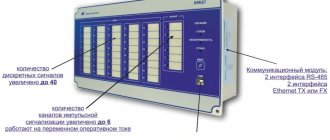
Rice. No. 4. The UZA-10 RS device is a device for relay protection, automation and control of connections.
Modern microprocessor devices, designed to replace conventional relay protection, are intended for new and reconstructed substations. They adapt to all types of high-voltage circuit breakers and work with various drive mechanisms. UZA-10 RS11 is mounted in relay cabinets of switchgears powered by current transformers and operative voltage supply circuits. Microprocessor units perform the function of a single automatic reclosure. They have an LED indication showing the operation of the protections and the automatic function of the device. Replacing electromechanical and semiconductor relays with new modern microprocessor devices does not require significant changes and reconstruction in existing control and automation circuits. No special installations are required to check devices.
Rice. No. 5. Table of functions performed by a microprocessor device
The functional blocks of microprocessor devices are distinguished by a clear delineation of tasks and are limited exclusively to relay protection functions, this achieves an increase in the degree of reliability to create a new concept for constructing relay protection.
Write comments or additions to the article, maybe I missed something. Take a look at the site map, I will be glad if you find anything else useful on my site.
Requirement for automatic reclosure
A number of mandatory requirements related to ensuring the reliability of power supply apply to automatic reclosure circuits and devices. These requirements include:
- The autorecloser must necessarily operate in the event of an emergency shutdown in the protected section of the network.
- The automatic reclosure should not operate if the circuit breaker trips immediately after turning it on via the control key. Such a trip indicates that there is permanent damage in the circuit, and the operation of the automatic reclosure device can aggravate the situation. To fulfill this requirement, they make sure that the automatic reclosure devices become ready only a few seconds after the circuit breaker is turned on. In addition, the automatic reclosure should not operate during operational switching operations carried out by personnel.
- The automatic reclosure circuit should be automatically blocked when a number of protections are triggered (for example, after the gas protection of a transformer has been activated, the operation of automatic reclosure devices is undesirable)
- Automatic reclosure devices must operate with a specified frequency. That is, a single automatic reclosure should operate 1 time, a double automatic reclosure should operate 2 times, etc.
- After successfully turning on the circuit breaker, the automatic reclosure circuit must automatically return to the ready state.
- The automatic reclosure must operate with a set time delay, ensuring the fastest possible restoration of power in the disconnected section of the network. As a rule, this shutter speed is 0.3-5 s. However, it should be noted that in some cases it is advisable to slow down the automatic reclosure operation to several seconds.
Purpose of automatic reclosing
The purpose of automatic restart involves starting the switching devices after an emergency de-energization of the lines. The use of automatic reclosure allows you to minimize the time period of power line outages.
Emergency situations can be (short circuits):
- short-term - for a random reason that lasts for a short time (from the movement of animals, falling trees, etc.);
- stable - if resuming line operation is impossible without personnel intervention, in case of wire breakage, damage to the insulating coating and other consequences.
As a result of an accident, the autorecloser is triggered no matter what the outcome. But resumption of work becomes possible only if the influence of the influencing factor is eliminated.
Operating principle of the automatic reclosure device
The use of the device may vary depending on the specific case. The automation uses the principle of turning off overhead lines with a voltage below 220 kV, or more precisely, the device checks the condition and position of the switch key. More precisely, if the device receives a signal about the absence of voltage, but the switch is in the on state, then an unplanned power outage has occurred. This principle of operation makes it possible to separate the problem and in the event of a planned power outage, the automatic reclosure or automatic reclosing device simply does not respond.
3.3.10
On single lines with double-sided power supply (in the absence of shunt connections), one of the following types of three-phase automatic reclosure (or combinations thereof) must be provided:
a) fast-acting TAPV (BAPV)
b) non-synchronous TAPV (NAPV);
c) TAPV with synchronism capture (TAPV US).
In addition, single-phase autorecloser (SAAR) may be provided in combination with various types of TARES, if the circuit breakers are equipped with phase-by-phase control and the stability of the parallel operation of parts of the power system in the SAAR cycle is not disrupted.
The choice of types of automatic reclosure is made based on the totality of specific operating conditions of the system and equipment, taking into account the instructions of 3.3.11-3.3.15.
Classification
Number of circuit breaker closings using automatic reclosure:
- One-time actions - after a short circuit, the system turns on only 1 time.
- Repeated action - turns on the system several times, usually 2.
According to the method of influencing the automatic reclosure switch, there can be:
- Mechanical - they are built into the spring drive of the switch.
- Electrical - act on the switch turning on electromagnet.
Autoreclosers are classified according to the number of phases used during operation. Devices can be:
- Single-phase - automatically introduces only one phase upon short circuit. Typically used for lines of 500 kV or more;
- Three-phase – ensure the switch operates with all three phases turned on;
- Combined - can be triggered due to the possibility of logical selection of the desired circuit or several phases.
Three-phase automatic reclosure devices can, depending on the operating conditions of the network, be divided into
- simple (TAPV);
- non-synchronous (NAPV);
- fast-acting (BAPV);
- with voltage presence check (APVNN);
- with voltage absence test (APVON);
- with anticipation of synchronization (APVOS);
- with synchronism capture (APVUS);
- in combination with self-synchronization of generators and synchronous compensators (SPVS);
- A special type of automatic reclosure is frequency automatic reclosing (FARC).
At the same time, three-phase devices are divided into the following subtypes:
- with one-way voltage supply - when only one high-voltage switch is triggered, and the power is supplied from one source;
- double-sided – with the ability to connect two switching devices.
Double-sided reclosures are divided into:
- circuits with non-synchronous re-closing - when two switches are simultaneously introduced without maintaining synchronism;
- waiting for synchronous operation - switching occurs sequentially, from opposite sides;
- catching synchronism - the moment for simultaneous activation is selected in order to smooth out possible undesirable effects as much as possible;
- fast action – minimizing the waiting time for re-activation.
Also read: Types of switchgears (RU)
In addition to the specified division, a classification is provided according to the method of operation - mechanical activation or electrical signal. Additionally, automatic reclosures are divided according to the number of stages into single- and multi-stage - trying to turn on the power once or repeatedly.
TAPV and OAPV.
The stability of the power system operation depends not only on the time of switching off the short circuit on the 500 kV overhead line, but also on the time of autoreclosure: power transmission along the overhead line stops at the moment the short circuit (three-phase) occurs and is resumed after the overhead line is turned on by the autorecloser device. That is, to increase the stability of the power system, it is necessary to reduce both the response time of the relay protection of the 500 kV overhead line and the autoreclose time.
The response time of relay protection during a short circuit on a 500 kV overhead line is almost always zero (approximately 20-60 ms). And it is fundamentally impossible to make the AR time equal to zero for several reasons, the main one of which is that the AR time delay must be greater than the response time of the backup protections at the opposite end of the overhead line (usually 2-3 stages of DZ and ZZ):
tARV.A = tSZ.B+tOFF.B+tDEION+tREC-tSZ.A-tOFF.A = tSZ.B+tRESC
Therefore, automatic reclosure on an overhead line with two-way power supply always has a time delay of several seconds.
An ingenious way out of this situation is to turn off not all three phases of the overhead line, but only one damaged phase, followed by automatic reclosing of this phase, for single-phase short circuits on overhead lines, which make up about 65% of all short circuits. At the same time, in the automatic reclosure cycle, a connection between parts of the power system remains between two undamaged phases of the overhead line and power is transmitted, which sharply increases the stability of the power system compared to a three-phase shutdown of the overhead line.
To ensure single-phase shutdown of overhead lines and subsequent single-phase automatic reclosure, automatic reclosure devices are used. The situation is complicated by the fact that, as a rule, relay protection devices do not detect the damaged phase; all relay protection only acts on shutdowns of three phases, regardless of the type of damage. And some types of protection, for example earth protection, fundamentally cannot determine the damaged phase. Therefore, the detection of the damaged phase, its switching off and on is carried out by the OAPV device.
In this case, the interaction of relay protection devices and OAPV is performed as follows:
1.
When any close short circuit occurs, the relay protection and the relay protection work in parallel in time: the relay protection determines whether the overhead line needs to be turned off, and the relay protection determines the damaged phase.
2.
Until the relay protection works, the OAPV does nothing, although it already knows which phases are damaged.
3.
If the relay protection decides that the overhead line needs to be turned off, it turns off the overhead line through the OAPV circuit. That is, relay protection does not issue a command to turn off three phases of the overhead line switch, but rather issues a command from the automatic relay to turn off the overhead line.
4.
If the autorecloser has determined that the short circuit is single-phase, then after receiving a command from the relay protection, it turns off only the damaged phase of the overhead line and, with a time delay, tries to turn it on again - single-phase autorecloser. If the short circuit has disappeared, then this is called a successful OAPV. If the short circuit occurs again, then the OAPV turns off all three phases of the overhead line (unsuccessful OAPV) and does not turn them on again.
Interaction of AIIB devices and relay protection.
For networks consisting of series-connected sections with their own circuit breakers and relay protection, the “Rules” provide for the following types of interaction between automatic reclosure and relay protection: acceleration of protection after automatic reclosing; acceleration of protection before automatic reclosure; use of automatic reclosing of different frequencies. These measures are intended to speed up the disconnection of the short circuit. and increasing the efficiency of automatic reclosure, as well as to ensure selective shutdowns of damaged areas in cases where relay protection in neighboring areas cannot have full selectivity stages. Acceleration of protection after automatic reclosure is carried out by using a pulse contact of a time relay in the overcurrent protection circuit or by briefly putting into operation an additional set of overcurrent protection. For example, in a 10 kV network consisting of three sections (Fig. 25, a), protections 1, 2, 3, due to close time delays, are triggered simultaneously during a short circuit. at point K, and for protections 1 and 2 these actions are non-selective.
Rice. 25. Schemes of 10 kV networks for which it is advisable to accelerate protection after automatic reclosure (a) and before automatic reclosure (b) The automatic reclosure device on circuit breaker 1 has the opportunity to operate first, since there is voltage on the side of the 10 kV buses of substation A. When the circuit breaker is turned on by the automatic reclosure device for a short period of time (about 1 s), the action of protection 1 is accelerated to 0.2 s (instead of 0.8 s). If k.z. occurred in section 1-2, then breaker 1 would be quickly tripped by this accelerated protection. But with short circuit at point K behind switches 2 and 3 that have switched off, protection 1 does not work and after 1 s its response time again becomes 0.8 s. After successful switching on of switch 1, voltage appears on the automatic reclosure circuit of switch 2. After a few seconds, the automatic reclosure device is triggered, switch 2 is turned on and at the same time protection 2 is accelerated to 0.2 s. But protection 2, like protection 1, does not work due to the fact that the short circuit. occurred at point K. If K.Z. was in section 2-3, protection 2 along the acceleration circuit would have worked faster than protection 1, and the selectivity level would have been sufficient: 0.6 s. After successful switching on of switch 2, voltage appears on the automatic reclosure circuit of switch 3. After a few seconds, the automatic reclosure device is triggered, switch 3 is turned on, at the same time the acceleration circuit of protection 3 is introduced to 0.2 s and switch 3 is turned off, much earlier than protection 2 could have acted. , in which by this time the accelerated stage of 0.2 s has already been taken out of action and a constant time setting of 0.7 s has been introduced (Fig. 25, a). Acceleration of protection on a direct operating current is simple and is provided for in standard design diagrams. To speed up protection on alternating operating current when using relays RT-80, RTV, RTM, additional equipment is required, so such circuits are rarely used. Acceleration of protection before automatic reclosure. This event allows you to speed up the disconnection of the short circuit. in a network consisting of several sections connected in series or to facilitate the operation of several switches due to one, more powerful and reliable. On switch / (Fig. 25.6), accelerated protection with a time delay of 0.2 s is permanently introduced. With short circuit at any point in the network, for example at point K, this protection turns off circuit breaker 1 before protections 2 and 3 are triggered. When the automatic reclosure device is triggered to turn on circuit breaker 1, this accelerated protection is taken out of action for the time required for selective shutdown of the closest circuit breaker. .z. switch 3. The circuit using constant operating current is very simple. Use of automatic reclosing of different frequencies. If the selectivity levels are insufficient (Fig. 25, a), automatic reclosure devices with different multiplicity of action can be used to correct non-selective shutdowns. For example, for the network diagram in Fig. 25, I could do the following: on switch 3 - single automatic reclosure, on switch 2 - double, on switch 1 - threefold, although automatic reclosure devices with a multiplicity of more than two are not produced by industry. Correction of non-selective actions using automatic reclosure of different multiplicities is used quite often both on adjacent sections and lines, and on lines with transformers on branches. In the latter case, automatic reclosure corrects the non-selective action of protection of a 10 kV line during a short circuit. in a transformer, when the melting time of 10 kV fuse inserts is commensurate with the response time of the line protection.
- Back
- Forward
Related links
- Rules for the technical operation of consumer electrical installations / Regulatory document dated February 9, 2007 at 02:14
- Electrician's Bible / Regulatory document January 14, 2014 at 12:32 pm
- Handbook on electrical networks 0.4-35 kV and 110-1150 kV. Volume 10 / Regulatory document from March 2, 2009 at 18:12
- Kabyshev A.V., Tarasov E.V. Low-voltage circuit breakers / Regulatory document dated October 1, 2021 at 09:22
- Rules for the installation of overhead power lines with voltage up to 1 kV with self-supporting insulated wires / Regulatory document dated April 30, 2008 at 15:00
- Knyazevsky B.A. Trunkovsky L.E. Installation and operation of industrial electrical installations / Regulatory document dated October 17, 2019 at 12:36
- Mankov V.D. Zagranichny S.F. Protective grounding and grounding of electrical installations / Regulatory document dated March 27, 2021 at 09:05
3.3.12
Non-synchronous automatic reclosure (NAPR) can be used on lines according to 3.3.10 (mainly 110-220 kV), if:
a) the maximum electromagnetic torque of synchronous generators and compensators that occurs during non-synchronous switching is less (taking into account the necessary margin) of the electromagnetic torque that occurs during a three-phase short circuit at the machine terminals, while the calculated initial values of the periodic components of the stator currents are taken as practical criteria for assessing the admissibility of NAPV at a switching angle of 180°;
b) the maximum current through the transformer (autotransformer) at a switching angle of 180° is less than the short-circuit current at its terminals when powered by infinite power buses;
c) after automatic reclosure, sufficiently fast resynchronization is ensured; If, as a result of non-synchronous automatic reclosing, a prolonged asynchronous operation is possible, special measures must be taken to prevent or stop it.
Subject to these conditions, NAPV can also be used in repair mode on parallel lines.
When performing NAPV, it is necessary to take measures to prevent unnecessary activation of the protection. For this purpose, it is recommended, in particular, to turn on the circuit breakers during autoreclose in a certain sequence, for example, by performing an autoreclose on one side of the line with monitoring the presence of voltage on it after a successful autoreclose on the opposite side.
Electrical laboratory » Questions and answers » PUE 7th edition » 3.3.2 - 3.3.29. Automatic reclosing (AR)
AUTOMATIC RECLOSURE (AR)
3.3.2. Automatic reclosure devices must be provided to quickly restore power to consumers or intersystem and intrasystem connections by automatically turning on circuit breakers disabled by relay protection devices. Automatic reconnection must be provided for: 1) overhead and mixed (cable-overhead) lines of all types with voltage above 1 kV. Refusal to use automatic reclosure must be justified in each individual case. On cable lines of 35 kV and below, automatic reclosure is recommended to be used in cases where it can be effective due to the significant probability of damage with the formation of an open arc (for example, the presence of several intermediate assemblies, power supply through one line of several substations), as well as for the purpose of correcting non-selective protection actions. The issue of using automatic reclosure on cable lines of 110 kV and above must be decided during the design in each individual case, taking into account specific conditions; 2) buses of power plants and substations (see 3.3.24 and 3.3.25); 3) transformers (see 3.3.26); 4) critical electric motors that are turned off to ensure self-starting of other electric motors (see 3.3.38). To carry out automatic reclosure according to clauses 1-3, automatic reclosing devices must also be provided on bypass, busbar and sectional switches. In order to save equipment, it is allowed to install a group autorecloser on lines, primarily cable, and other connections of 6-10 kV. In this case, one should take into account the disadvantages of the group autoreclose device, for example, the possibility of failure if, after opening the circuit breaker of one of the connections, the circuit breaker of the other connection is turned off before the automatic reclosure device returns to its original position.
3.3.3. Autorecloser devices must be designed so that they do not operate when: 1) the circuit breaker is disconnected by personnel remotely or using remote control; 2) automatic disconnection from relay protection immediately after switching on by personnel remotely or using remote control; 3) disconnection of the circuit breaker by protection against internal damage to transformers and rotating machines, emergency automatic devices, as well as in other cases of circuit breaker tripping when the action of automatic reclosure is unacceptable. Automatic reclosing after the action of the emergency response (CAPR) must be performed in accordance with 3.3.81. Autorecloser devices must be designed in such a way that the possibility of repeated short-circuit activation in the event of any fault in the device circuit is excluded. Automatic reclosure devices must be designed with automatic return.
3.3.4. When using automatic reclosure, as a rule, provision should be made for accelerating the action of relay protection in case of unsuccessful automatic reclosure. Acceleration of the action of relay protection after an unsuccessful automatic reclosure is carried out using an acceleration device after turning on the circuit breaker, which, as a rule, should also be used when turning on the circuit breaker for other reasons (from the control key, remote control or automatic transfer device). When accelerating protection after switching on the switch, measures must be taken against possible tripping of the switch by the protection under the influence of a current surge when switching on due to non-simultaneous switching on of the switch phases. You should not accelerate protection after turning on the switch, when the line is already energized by another switch (i.e., when there is symmetrical voltage on the line). After automatic reclosure, it is allowed not to accelerate the action of protections for lines of 35 kV and below, made on alternating operating current, if this requires significant complication of the protection and the time of their action in case of a metal short circuit near the installation site does not exceed 1.5 s.
3.3.5. Three-phase autoreclose devices (TAAR) should be carried out primarily with start-up in the event of a discrepancy between the previously issued operational command and the open position of the circuit breaker; It is also allowed to start the automatic reclosure device from protection.
3.3.6. As a rule, single-acting or double-acting TAVR devices can be used (the latter - if this is permissible under the operating conditions of the circuit breaker). A double-acting TAVR device is recommended for overhead lines, especially for single ones with one-way supply. In networks of 35 kV and below, double-acting TAVR devices are recommended to be used primarily for lines that do not have network redundancy. In networks with an isolated or compensated neutral, as a rule, blocking of the second autoreclose cycle should be used in the event of a ground fault after the autoreclose of the first cycle (for example, due to the presence of zero-sequence voltages). The TAPR time delay in the second cycle should be at least 15-20 s.
3.3.7. To speed up the restoration of normal operation of the power transmission, the time delay of the TAVR device (especially for the first cycle of double-acting automatic reclosure on lines with one-way power supply) should be taken as minimal as possible, taking into account the time of arc extinction and deionization of the medium at the fault site, as well as taking into account the readiness time of the circuit breaker and its drive to restart. The time delay of the TAVR device on a line with two-way power supply should also be selected taking into account the possible non-simultaneous disconnection of a fault at both ends of the line; in this case, the duration of protection intended for long-distance backup should not be taken into account. It is allowed not to take into account the different times of switching off of switches at the ends of the line when they are switched off as a result of the operation of high-frequency protection. In order to increase the efficiency of single-acting TAPV, it is allowed to increase its time delay (if possible, taking into account the work of the consumer).
3.3.8. On single lines of 110 kV and above with one-way power supply, for which a transition to long-term operation with two phases is permissible in case of unsuccessful TAVR, double-acting TAVR should be provided at the supply end of the line. Conversion of the line to two-phase operation can be carried out by personnel on site or using remote control. To transfer a line after an unsuccessful automatic reclosure to two-phase operation, phase-by-phase control of disconnectors or switches at the supply and receiving ends of the line should be provided. When transferring a line to long-term operation in two phases, measures should be taken, if necessary, to reduce interference in the operation of communication lines due to the open-phase operating mode of the line. For this purpose, it is allowed to limit the power transmitted through the line in single-phase mode (if this is possible under the operating conditions of the consumer). In some cases, if there is a special justification, an interruption in the operation of the communication line for the duration of the open-phase mode is also allowed.
3.3.9. On lines whose disconnection does not lead to disruption of the electrical connection between generating sources, for example on parallel lines with one-way power supply, TAVR devices should be installed without checking synchronism.
3.3.10. On single lines with double-sided power supply (in the absence of shunt connections), one of the following types of three-phase autorecloser (or combinations thereof) must be provided: a) high-speed autorecloser (SARES) b) non-synchronous autorecloser (NARES); c) TAPV with synchronism capture (TAPV US). In addition, single-phase autorecloser (SAAR) may be provided in combination with various types of TARES, if the circuit breakers are equipped with phase-by-phase control and the stability of the parallel operation of parts of the power system in the SAAR cycle is not disrupted. The choice of types of automatic reclosure is made based on the totality of specific operating conditions of the system and equipment, taking into account the instructions of 3.3.11-3.3.15.
3.3.11. It is recommended to provide high-speed automatic reclosure, or simultaneous reclosure with a minimum time delay at both ends, on lines according to 3.3.10 for automatic reclosure, as a rule, when there is a slight discrepancy in the angle between the EMF vectors of the connected systems. BARP can be used in the presence of circuit breakers that allow BARP, if after switching on the preservation of synchronous parallel operation of the systems is ensured and the maximum electromagnetic torque of synchronous generators and compensators is less (taking into account the required margin) of the electromagnetic torque that occurs during a three-phase short circuit at the machine terminals. The assessment of the maximum electromagnetic moment should be made for the maximum possible angle divergence during the BARP. Accordingly, the BAPV should be launched only when the high-speed protection is triggered, the coverage area of which covers the entire line. The BARP must be blocked when backup protections are triggered and blocked or delayed when the breaker failure protection is operating. If in order to maintain the stability of the power system in the event of unsuccessful BARP, a large volume of impacts from emergency automatics is required, the use of BARP is not recommended.
3.3.12. Non-synchronous automatic reclosure (NAPV) can be used on lines according to 3.3.10 (mainly 110-220 kV), if: a) the maximum electromagnetic torque of synchronous generators and compensators that occurs during non-synchronous switching is less (taking into account the necessary margin) of the electromagnetic torque that occurs with a three-phase short circuit at the machine terminals, while the calculated initial values of the periodic components of the stator currents at a switching angle of 180° are taken as practical criteria for assessing the admissibility of NAPV; b) the maximum current through the transformer (autotransformer) at a switching angle of 180° is less than the short-circuit current at its terminals when powered by infinite power buses; c) after automatic reclosure, sufficiently fast resynchronization is ensured; If, as a result of non-synchronous automatic reclosing, a prolonged asynchronous operation is possible, special measures must be taken to prevent or stop it. Subject to these conditions, NAPV can also be used in repair mode on parallel lines. When performing NAPV, it is necessary to take measures to prevent unnecessary activation of the protection. For this purpose, it is recommended, in particular, to turn on the circuit breakers during autoreclose in a certain sequence, for example, by performing an autoreclose on one side of the line with monitoring the presence of voltage on it after a successful autoreclose on the opposite side.
3.3.13. Automatic reclosure with synchro-catching can be used on lines according to 3.3.10 to turn on the line with significant (up to approximately 4%) slips and permissible angle. The following automatic reclosure is also possible. At the end of the line, which must be turned on first, an accelerated TAPV is performed (with recording of the operation of high-speed protection, the coverage area of which covers the entire line) without monitoring the voltage on the line (UTAPV BK) or TAPV with monitoring the lack of voltage on the line (TAPV ON), and at at its other end is TAPV with synchronism capture. The latter is carried out provided that the switching on of the first end was successful (this can be determined, for example, by monitoring the presence of voltage on the line). To capture synchronism, devices built on the principle of a synchronizer with a constant advance angle can be used. Autorecloser devices should be designed in such a way that it is possible to change the order of switching on the switches at the ends of the line. When implementing a self-reclosing device, it is necessary to strive to ensure its operation with the largest possible frequency difference. The maximum permissible switching angle when using autorecloser must be taken taking into account the conditions specified in 3.3.12. When using the US autorecloser device, it is recommended to use it to switch on the line by personnel (semi-automatic synchronization).
3.3.14. On lines equipped with voltage transformers, to control the absence of voltage (KOH) and control the presence of voltage (VVV) on the line for various types of TAPV, it is recommended to use elements that respond to linear (phase) voltage and to negative and zero sequence voltages. In some cases, for example on lines without shunt reactors, zero sequence voltage may not be used.
3.3.15. Single-phase automatic reclosing (SAR) can only be used in networks with large ground fault currents. OAPV without automatic transfer of the line to a long-term open-phase mode in case of persistent phase damage should be used: a) on single, heavily loaded inter-system or intra-system power lines; b) on heavily loaded intersystem lines of 220 kV and above with two or more bypass connections, provided that disconnecting one of them may lead to a violation of the dynamic stability of the power system; c) on intersystem and intrasystem lines of different voltage classes, if a three-phase shutdown of a high voltage line can lead to an unacceptable overload of low voltage lines with the possibility of disrupting the stability of the power system; d) on lines connecting large block power plants with the system without significant local load; e) on power lines, where the implementation of TAPV is associated with significant load shedding due to a decrease in voltage. The automatic reclosure device must be designed in such a way that when it is taken out of operation or the power supply is lost, the action of the line protection is automatically switched to disconnect three phases in addition to the device. The selection of damaged phases during a short-circuit to ground must be carried out using selective bodies, which can also be used as additional high-speed protection of the line in the OAPV cycle, with TAPV, BAPV and one-way switching on of the line by operating personnel. The time delay of the AR should be adjusted to the time of arc extinction and deionization of the medium at the site of a single-phase short circuit in a single-phase mode, taking into account the possibility of non-simultaneous operation of the protection at the ends of the line, as well as the cascade action of the selective bodies.
3.3.16. On lines according to 3.3.15, OAPV must be used in combination with various types of TAPV. At the same time, it should be possible to prohibit TAPV in all cases of OAPV or only in case of unsuccessful OAPV. Depending on the specific conditions, TAPV may be performed after unsuccessful OAPV. In these cases, provision is made for the operation of TAPV first at one end of the line with control of the absence of voltage on the line and with an increased time delay.
3.3.17. On single lines with double-sided power supply connecting the system with a low-power power plant, TAPV with automatic self-synchronization (APWS) of hydrogenerators for hydroelectric power plants and TAPV in combination with dividing devices for hydro- and thermal power plants can be used.
3.3.18. On lines with double-sided power supply, in the presence of several bypass connections, the following should be used: 1) in the presence of two connections, as well as in the presence of three connections, if a simultaneous long-term disconnection of two of these connections is likely (for example, a double-circuit line): non-synchronous automatic reclosure (mainly for lines 110-220 kV and subject to the conditions specified in 3.3.12, but for the case of disconnecting all connections); AR with synchronism check (if it is impossible to perform non-synchronous AR for the reasons specified in 3.3.12, but for the case of disconnection of all connections). For critical lines in the presence of two connections, as well as in the presence of three connections, two of which are a double-circuit line, if it is impossible to use NAPV for the reasons specified in 3.3.12, it is allowed to use OAPV, BAPV or US AR devices (see 3.3.11 , 3.3.13, 3.3.15). In this case, OAPR and BAPV devices should be supplemented with an automatic reclosure device with synchronism check; 2) in the presence of four or more connections, as well as in the presence of three connections, if in the latter case a simultaneous long-term disconnection of two of these connections is unlikely (for example, if all the lines are single-circuit), - automatic reclosure without checking synchronism.
3.3.19. Autoreclosure devices with synchronism checking should be performed at one end of the line with control of the absence of voltage on the line and with control of the presence of synchronism, at the other end - only with control of the presence of synchronism. The circuits of the automatic reclosure device with line synchronism checking must be made identical at both ends, taking into account the possibility of changing the order of switching on the line switches during automatic reclosure. It is recommended to use an automatic reclosure device with a synchronism check to check the synchronism of the connected systems when the line is switched on by personnel.
3.3.20. The combined use of several types of three-phase autorecloser on a line is allowed, for example, BARES and TARES with synchronism check. It is also possible to use various types of automatic reclosure devices at different ends of the line, for example, UTAPV BK (see 3.3.13) at one end of the line and TAPV with monitoring the presence of voltage and synchronism at the other.
3.3.21. A combination of TAPV with non-selective high-speed protection is allowed to correct the non-selective action of the latter. In networks consisting of a number of lines connected in series, when using non-selective high-speed protection for them, it is recommended to use alternate automatic reclosure to correct their action; Automatic reclosure devices can also be used with acceleration of protection to automatic reclosure or with a multiplicity of action (no more than three), increasing towards the power source.
3.3.22. When using three-phase single automatic reclosure of lines supplying transformers, on the high voltage side of which short circuiters and separators are installed, in order to turn off the separator during a dead pause, the operating time of the automatic reclosure device must be adjusted from the total time of turning on the short circuiter and turning off the separator. When using a three-phase double-action automatic reclosure (see 3.3.6), the duration of the automatic reclosure in the first cycle according to the specified condition should not increase if the separator is switched off during the dead pause of the second automatic reclosure cycle. For lines on which separators are installed instead of circuit breakers, the disconnection of the separators in the event of unsuccessful automatic reclosure in the first cycle must be carried out during the dead pause of the second automatic reclosure cycle.
3.3.23. If, as a result of the automatic reclosure action, non-synchronous switching on of synchronous compensators or synchronous electric motors is possible and if such switching on is unacceptable for them, as well as to exclude power supply from these machines to the fault location, it is necessary to provide for automatic shutdown of these synchronous machines when the power supply fails or to transfer them to asynchronous mode by turning off the AGP with subsequent automatic switching on or resynchronization after voltage restoration as a result of successful automatic reclosure. For substations with synchronous compensators or synchronous electric motors, measures must be taken to prevent unnecessary AFR operations during automatic reclosure.
3.3.24. Reclosure of busbars of power plants and substations, in the presence of special protection of busbars and circuit breakers that allow reclosure, should be carried out in one of two options: 1) automatic testing (putting the busbars under voltage with a circuit breaker from the reclosure of one of the supply elements); 2) automatic circuit assembly; in this case, one of the supply elements (for example, a line, transformer) is turned on first from the automatic reclosure device; if this element is successfully turned on, a subsequent, possibly more complete automatic restoration of the pre-emergency mode circuit is carried out by turning on other elements. Automatic reclosure of busbars according to this option is recommended to be used primarily for substations without constant personnel duty. When performing automatic reclosure of busbars, measures must be taken to prevent asynchronous activation (if it is unacceptable). The busbar protection must be sufficiently sensitive in the event of an unsuccessful autoreclosure.
3.3.25. At two-transformer step-down substations with separate operation of transformers, as a rule, automatic reclosure devices for medium and low voltage buses should be provided in combination with automatic transfer switch devices; In case of internal faults of transformers, an automatic relay must operate; in case of other faults, an automatic reclosing force must be used (see 3.3.42). It is allowed for a two-transformer substation, in the normal mode of which parallel operation of transformers on busbars of a given voltage is provided, to install, in addition to the automatic reclosure device, an automatic transfer device intended for the mode when one of the transformers is put into reserve.
3.3.26. All single step-down transformers with a capacity of more than 1 MB A at substations of power systems that have a circuit breaker and maximum current protection on the supply side should be equipped with automatic reclosure devices when turning off the transformer leads to de-energization of consumer electrical installations. In some cases, automatic reclosure is also allowed when the transformer is disconnected by protection against internal damage.
3.3.27. If the automatic reclosure of an element connected by two or more circuit breakers is unsuccessful, automatic reclosing of the remaining circuit breakers of this element should, as a rule, be prohibited.
3.3.28. If there are switches with an electromagnetic drive at the substation or power plant, if two or more switches can be turned on simultaneously from the automatic reclosing device, in order to ensure the required voltage level of the battery when turned on and to reduce the cross-section of the cables of the power circuits of the switching electromagnets, as a rule, automatic reclosing should be performed as follows so that the simultaneous activation of several circuit breakers is excluded (for example, by using automatic reclosure at connections with different time delays). It is allowed in some cases (mainly at a voltage of 110 kV and a large number of connections equipped with automatic reclosure) to simultaneously turn on two circuit breakers from automatic reclosing.
3.3.29. The operation of automatic reclosure devices must be recorded by indicating relays, operation indicators built into the relay, operation counters or other devices of similar purpose.
Main purposes of application
In electrical networks, all types of damage can be divided into two groups:
- sustainable;
- unstable.
Persistent types include damage to the electrical network that does not recover on its own over time. To eliminate them, the help of specialists, or rather, an emergency team, is required. Such damage most often includes rupture of wires or damage to a section of the line, due to which further operation of the electrical network is impossible.
Unstable type damage is characterized by voltage restoration some time after the breakdown. For example, such a breakdown may occur after the wires are caught together, and an electric arc occurs, which does not cause significant damage to the electrical network. Due to the small amount of time during a short circuit, the entire power circuit is under relay protection. In practice, the number of intermittent faults is about 50–90% of all cases of electrical network breakdowns.
Solving the problem is possible without the presence of the system, but this device is responsible for accelerating the recovery process, and also completely takes over the automation work.
The automatic reclosing and automatic reclosing device system itself has become widespread and is used in electrical networks and substations. The device is combined with other types of relay automation, which makes it possible to fully automate work at substations, while eliminating the need to use an operational worker directly at the power grid facility. Also, the use of an automatic restart device at substations makes it possible to avoid the factor of errors during the work of maintenance personnel.
As indicated in the PUE, the automatic reclosure device must be used on all cable-overhead and overhead lines that have an operating voltage of 1 kV or higher. Additionally, transformers, electric motors, and substation busbars can be equipped with an automatic restart system.
Types of automatic reclosing
There are different types of automatic reclosers. First of all, autoreclosers are devices that use operational alternating current. These designs are equipped with auxiliary contacts included in the circuit to work together with certain elements that ensure reliable operation of the switching device drive. They consist of three contact groups responsible for the action of a particular section: they change the spring tension, ensure the functioning of the switch drive shaft and prompt shutdown in an emergency.
Other automatic reclosure devices require rectified operating current. Their main structural element is the complete relay RPV-358, which is activated when high-voltage circuit breakers are turned off in the event of any malfunction. The use of this relay allows you to avoid repeated operation of the switch in emergency situations affecting internal operating circuits.
A special feature of the autorecloser circuit with two-way power supply is the supply of power to the line from both sides at once. This method allows you to quickly restore the working state of the power supply. The only condition is to prevent repeated asynchronous switching. In some cases, automatic reclosure without synchronization can be used when there is high-speed protection installed in parallel circuits.
There are automatic three-phase restart systems in which the line is not synchronized with the two-way power supply. They are used in parallel lines, similar to single-sided reclosure. The design includes high-speed and non-synchronous devices. There are the same devices equipped with controllers that provide synchronization on lines with double-sided power supply. The design includes a relay that protects the line from being turned on when the angles between the EMF vectors are significant.
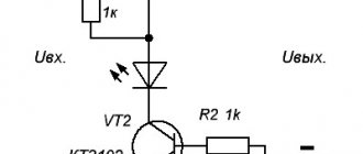
Design and principle of operation
You can get acquainted with the device and operating principle of automatic reclosure using the following diagram as an example:
The current is supplied here through the CC control bus. Automatic reclosure is controlled using the following mechanisms:
- controlling synchronization;
- controlling the contacts of the switching device;
- prohibiting inclusion;
- allowing preparation.
Temporary and intermediate relays (RV and RP) provide protection. The intermediate relay is made with two windings: current and voltage. During normal operation, a current is supplied to the control panel, charging the condensing element C, if a corresponding signal is received from the preparation enable circuit.
The possibility of restarting is prevented by a prohibiting circuit, the setting of which is ensured by series-connected resistors R1 and R2.
When the line is disconnected, the autorecloser is triggered by sending a signal to the circuit that controls the synchronization. Its contacts close and resistor R is shunted, and the capacitor is discharged into the RP coil. At the same time, the current coil is also excited, closing the relay contacts in the network.
Also read: Purpose of dielectric gloves in electrical installations
In the event of a three-phase short-circuit termination, the automatic reclosure is triggered and the PV winding is opened. Then resistor R is connected and the relay returns to the de-energized state.
The use of node H allows for the safe performance of line maintenance work by operating personnel.