Purpose and scope of application of the technique.
1.1 This document, method No. 5 “ Checking the performance of a residual current device (RCD )” establishes a method for testing the functionality of a residual current device (RCD) in electrical installations with voltages up to 1000 V for compliance with the requirements of regulatory documentation by electrical laboratory specialists.
1.3 The check is carried out on the basis of the requirements of GOST R 50571.16-99 (clause 612.6.1) and GOST R 50807-95.
2. Characteristics of the measured quantity, standard values of the measured quantity.
The object of testing is RCDs (residual current devices) of type A and AC, designed to operate only in 380\220 V alternating voltage networks with a solidly grounded neutral.
Preparing to take measurements
7.1 Checking technical documentation
— The set of technical documentation should include:
— certificate of compliance with RCD GOST R51356-1-99;
— passport (operating manual) for the RCD with the manufacturer’s Quality Control Department stamp, date of manufacture, sales stamp, indication of the warranty period;
— accompanying technical documentation of the manufacturer.
— The accompanying technical documentation and marking of the RCD must contain information about the method and location of installation, the number of poles and the number of current-carrying conductors, rated voltage, rated current, rated breaking differential current, maximum shutdown time, rated non-breaking differential current, rated making and breaking capacity , as well as by differential current, limit value of non-tripping current under overcurrent conditions, rated conditional short circuit current, recommended switching circuit.
7.2 Checking the correct installation of the RCD in the electrical installation diagram. The check should include the validity of the RCD protection zone, compliance of its parameters with standardized values, parameters of overcurrent protection devices, and compliance of the overcurrent protection characteristics of the RCD with the calculated parameters of the network.
7.3 Checking the fixation of the RCD control in two extreme positions: “ON”; "OFF".
7.4 Checking the operation of the RCD when the operating voltage is turned on by pressing the “Test” button five times. Each time the button is pressed, the RCD contacts should open.
Execution
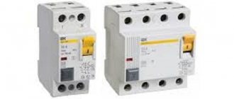
By design there are: RCD on DIN rail, Diffavtomat, sockets-RCD, adapters-RCD, plugs-RCD.
RCD on DIN rail
An RCD on a DIN rail is a modular device that is installed in an electrical panel. Installing an RCD in a switchboard is most desirable. The cost of such an RCD is relatively low (1000-3000 rubles). However, remember: the RCD does not replace the circuit breaker! There should always be an overcurrent protection circuit breaker in front of it.
Differential machines
There are types of RCDs that have a built-in circuit breaker. They are called differential automata. Differential circuit breakers combine the functions of circuit breakers and RCDs, and their size is the same as that of a conventional RCD, thus saving space on the DIN rail. An additional characteristic of such a device is the rated current of the circuit breaker and its response characteristic (usually “C”). The cost of a differential circuit breaker is usually 30-50% higher than the corresponding RCD and the circuit breaker separately; the number of models is very limited. In a good quality diffautomatic device there is always a window that is painted a certain color when it is triggered and you can understand why it triggered: from short circuit overcurrents or from leakage currents.
RCD sockets
They are installed if the electrical wiring is old and noisy, or if there is no desire or opportunity to install an RCD for the entire apartment. They cost an order of magnitude more than the corresponding RCD for DIN rail (10,000-20,000 rubles). When installing, they require a deep mounting box (60 mm or deeper).
Adapter-UZO
They are used when they don’t want to bother themselves with connections or call a technician to connect the RCD. It is also convenient when using portable devices.
Sequence and order of testing (measurements).
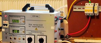
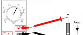
8.1. Assemble the test circuit as shown in Fig. 1
Fig.1. Measurement of equipment equipped with an RCD using a pointed probe or a plug-type probe (neutral wire may not be connected).
8.2 Measuring the response time of the RCD.
To measure the response time of the RCD and active grounding resistance, you must:
— connect L, N (neutral wire may not be connected) and PE electrical equipment in accordance with Fig. 6;
— using the switch, select the measurement function RE, tA and the specified multiple of the rated differential current;
— using key 11, select a selective or conventional RCD switch;
— using key 10, select the safe voltage value;
— using key 9, select the nominal value of the residual current switch;
— using key 8, select the type of test current and the initial phase (in the case of a sinusoidal type);
- when you press key 6, RE is measured, the result is displayed on the main reading field 15
— when you press 6 again; t D is measured.
In the case of selective switches, after starting the measurement there will be a delay of 30 seconds, which is signaled in the main field.
After the RCD circuit breaker is turned off, the response time value will be displayed in the main field 15.
Using key 13, you can display the result of measuring the active grounding resistance RE. Pressing this key again will return to pin tA. While both measurement results are displayed, additional field 16 displays the rated current value set for this type of switch.
8.3 Measurement of contact voltage and inrush current of RCD.
– In order to measure the inrush current, it is necessary:
– connect L, N (the neutral wire does not need to be connected) and PE from the electrical equipment in accordance with Fig. 6;
– use the switch to select the measurement function UB, ID;
– using key 11, select a selective or conventional RCD switch;
– using key 10, select the safe voltage value;
– using key 9, select the rated value of the differential current of the switch being measured;
– using key 8, select the type of test current and the initial phase (in the case of a sinusoidal type);
– when pressing key 6; Uв is measured, the result is displayed on the main reading field 15
– when you press 6 again; ID measurement is performed. If the RCD switch is turned off, then the inrush current value will be displayed in the main field 15.
Pressing this key again will return to the I D pin.
While both measurement results are displayed, additional field 16 displays the rated current value set for this type of switch.
If we are only interested in measuring the contact voltage UB, before the next measurement we must press key 8, which will end the inrush current measurement step IA.
8.4 Automatic measurement of RCD operating parameters.
In order to measure all RCD starting times, as well as the starting current IA, contact voltage UB and active resistance RE, you can use the automatic measurement function.
There is no need to start the measurement every time, you only need to initiate the measurement and turn on the RCD after each trip.
For the set rated current value of the circuit breaker and the selected type of current, the device performs a series of measurements in the following sequence:
| No. | Measured parameters | Measurement conditions | |
| Sinusoidal current | Unidirectional ripple current | ||
| 1. | UB, RE | ||
| 2. | tA | 0.5IDn | 0.5IDn |
| 3. | tA | 0.5IDn | 0.5IDn |
| 4.* | tA | 1IDn | 1IDn |
| 5.* | tA | 1IDn | 1IDn |
| 6.* | tA | 5IDn | 5IDn |
| 7.* | tA | 5IDn | 5IDn |
| 8.* | I.A. | ||
| 9.* | I.A. |
* points in which, provided that the RCD switch is in working order, it should turn off.
If during the measurement process the RCD is triggered (switched off), the display will display the message 54 , informing you that it needs to be turned on.
After turning on the RCD, the measuring device will perform the following measurement. If the meter worked correctly, then after the series of changes is completed, the display shows the inscription 49.
If the switch operates at half the current I Dn or does not operate in other cases, the measurement process is interrupted and the message 50 appears on the display.
The measurement is also interrupted if the preset safety voltage UL is exceeded.
In order to carry out automatic measurement of RCD parameters, it is necessary:
– connect L, N (neutral wire may not be connected) and PE electrical equipment in accordance with Fig. 1;
– use the switch to select the Auto measurement function;
– using key 11, select a selective or conventional RCD switch;
– using key 10, select the safe voltage value;
– using key 9, select the nominal value of the residual current switch;
– using key 8, select the type of test current 55 or 57 (the phase changes automatically during the measurement process);
– when pressing key 6; measurement is made;
– after each operation of the switch, turn it on again.
Individual components of a set of measurement results can be viewed using key 13. The display of individual results corresponds to mnemonics that appear in additional field 16 and describe the type of measurement being performed, as well as symbols 55 and 56 or 57 and 58, which determine the type, as well as the initial phase or polarization of the current.
8.5. The procedure for measuring the leakage current of group networks:
— turn off the load breakers, turn on the RCD;
— measure the response current of the RCD ID1;
— turn on the load breakers, turn on the RCD;
— measure the response current of the RCD ID2.
— Determine Iut = ID1-ID2. I ut should not exceed 1/3 IDn.
Differential circuit breakers and RCDs
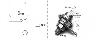
Residual current device (RCD) is a protective switch that is triggered when there is a current leak. ATTENTION! Does not protect against overload and short circuit, installed only together with a circuit breaker!
The operating principle is based on multidirectional currents, the sum of which is 0, I1 + I2=0. If the insulation is broken, if it is an electrical device with a metal body that is grounded, the current will flow to the ground, respectively, I1 + I2≠0 and the RCD will trip. But if the case is not grounded, then the current will not flow, but will “stay” on the case until a person touches it. A leak will occur, the RCD will turn off the lines, but the person will feel an electric shock. Therefore, a prerequisite for the correct operation of the RCD is the presence of a grounding loop and grounding of metal cases and parts of electrical appliances.
processing of measurement results
9.1 MIE 500 device specifications:
Table 9. RCD switch-off test and response time measurement (tD)
| Switch type | Installation multiplicity | Range measurements | Permission. | Error |
| General type | 0.5 IDN | 0..200ms | 1 ms | ± 2% i.v. ±1 unit ml. category |
| 1 IDN | ||||
| 2 IDN | 0..150ms | |||
| 5 IDN | 0..40ms | |||
| Selective | 0.5 IDN | 0..500ms | ||
| 1 IDN | ||||
| 2 IDN | 0..200ms | |||
| 5 IDN | 0..150ms |
differential current setting accuracy
for 1хIDN, 2хIDN, i 5хIDN…………………………………………………………………….. 0…5%
for 0.5*IDN…………………………………………………….. –5…0%
Table 10. RCD inrush current measurement for sinusoidal residual current (IA)
| Selected rated current of the circuit breaker | measurement range | Permission. | Current measured | Error |
| 10 mA | 3.3..10.0mA | 0.1 mA | 0.3 x IDn..1.0 x IDn | ± 5% IDn |
| 30 mA | 9.0..30.0 mA | |||
| 100 mA | 33..100 mA | 1 mA | ||
| 300 mA | 90..300 mA | |||
| 500 mA | 150..500 mA |
Table 11. Measurement of RCD inrush current for differential pulsating
unidirectional current (ID)
| Selected rated current of the circuit breaker | measurement range | Permission | Current measured | Error |
| 10 mA | 4..20 mA | 0.1 mA | 0.4 x IDn..2.0 x IDn | ± 10% IDn |
| 30 mA | 12..42 mA | 0.4 x IDn..1.4 x IDn | ± 7% IDn | |
| 100 mA | 40..140 mA | 1 mA | ||
| 300 mA | 120..420mA |
– measurement is possible for positive or negative half-cycles of leakage current
– the flow time of the measurement current is maximum. 2560 ms
nominal temperature…………………………………. +20..+25°C
- temperature coefficient for inrush current measurement:………………± 0.5% / 10°C.
8.3 Processing of measurement results of the differential breaking current of the RCD and leakage currents of group lines.
Measurement of differential breaking current RCD-20 VAD-1 with rated breaking current IDn = 30 mA, designed to protect three group network lines, installed in front of the circuit breakers of these lines. Temperature when measuring 30°C. Temperature coefficient for measuring inrush current ± 0.5% / 10°C.
When measuring the differential tripping current of the RCD (circuit breakers are turned off), the device readings are 20 mA.
When measuring the disconnecting current of the RCD, taking into account the network leakage currents (circuit breakers are turned on), the device readings are 15 mA.
In the first case, ID = 20 ± 1.05 mA, which meets the requirements of GOST R51356-1-99 (0.5IDnDDn).
In the second case, ID = 15 ± 0.79 mA, and the network leakage current Iut = 5 ± 1.84 mA, which also meets the requirements of regulatory documents (clause 7.1.83 PUE), namely: the network leakage current should not exceed one thirds of the rated differential breaking current of the RCD.
Requirements for the use of RCDs: rated cut-off current and response time
I would like to talk a little about the rated operating currents of the RCD. In principle, RCDs are produced with cutoff ratings from 0.0006 A to 30 A. For apartments, RCDs with currents of 0.01 A and 0.03 A are used. For a house, a 100 mA or 300 mA RCD is installed at the entrance for fire safety.
You need to understand that as the sensitivity of the RCD increases, the permissible response time also increases. Thus, an RCD with a cut-off current of 30 mA (0.03 A) should operate in 0.5 seconds, and an RCD with a cut-off current of 10 mA (0.01 A) can already be produced with a trip current of 5 seconds. So you also need to pay attention to the response time when purchasing an RCD.
Related articles: Protection from direct contact
SECURITY MEASURES
RCD testing work is carried out as ordered. In premises, except those that are particularly dangerous in terms of electric shock, an employee who has group III electrical safety and the right to be a work performer can carry out RCD tests alone. The list of necessary technical measures to prepare the workplace is determined by the employee issuing the order.
Particular attention should be paid to pp. 1.4.5; 1.4.6; 1.4.7; 1.4.11 IPBEE.
When conducting tests, it is necessary to use at least one primary and one additional means of protection.
The main parameters of the RCD printed on its body
I would like to note right away that depending on the manufacturer and country of manufacture, the number of parameters may be less.
1. Designations of terminals for connecting the device to the supply circuit.2.
Designations of the terminals for connecting the load to the device. 3. Device manufacturer . In an abbreviated version, the author's logo. 4. RCD model . Device model according to the manufacturer’s product range. Most often in an abbreviated version. 5. Rated current . The value of the current that the RCD can pass in normal “closed” mode. 6. Rated voltage : The voltage value for which the device is designed. 7. Rated current frequency : The current frequency value for which the RCD is designed. For one RCD there can be several current frequency values. 8. Differential operating current . The value of the differential current at which the RCD trips (opens). This value can be called the non-triggering current, that is, up to this value the RCD will operate in the “closed” mode. 9. Letter type of RCD, according to the type of differential operating current. Accepted letters: A, AC, B, S, G.
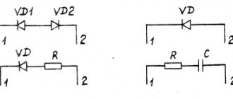
10. Schematic designation of the RCD type according to the type of tripping current;
11. Temperature characteristics of RCD. More often, the minimum temperature at which the RCD will remain operational is indicated; 12. RCD connection diagram. In itself, the scheme does not have much practical significance. However, it is important for instantly determining the type of RCD based on the dependence of the RCD’s performance on the power supply to it. Related articles: General requirements for the use of RCDs
Let's stop here.
There are two types of RCDs depending on the power supply of the device. An electromechanical RCD does not require power supply to the input terminals; such an RCD is triggered using the power of the differential current.
Electronic RCDs do not work without power supply to the input terminals. Their circuit contains a current amplifier that will not work without a third-party source.
Electromechanical RCDs are more stable and reliable.
13. The magnitude of the short-circuit current (short circuit). Let me remind you that an RCD without overcurrent protection does not “see” a short circuit and does not turn off the circuit when short circuit overcurrents appear. But with overcurrents, a large amount of thermal energy is released, and so, this value of the short-circuit current indicated on the device body shows what overcurrent value the RCD will withstand. 14. There are two badges left: Rosstandart and the fire resistance standard. The symbols are formal and mean that the RCD has passed all the necessary tests according to GOST.