What is an electromagnetic relay, device, purpose
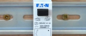
An electromagnetic relay is a switching device that uses an electromagnetic field to operate. It consists of an electromagnetic coil and a movable armature, movable and fixed contacts. The anchor and reel are fixed to the base. The anchor is spring-loaded and positioned so that the fixed contacts have points of contact with the fixed contacts.
Electromagnetic relay device
How does an electromagnetic relay work? When voltage is applied to the winding, an electromagnetic field appears in it. The movably fixed armature is attracted to the coil core, the contacts switch (close/open). This is the job of the relay - to transfer contacts. Different loads are connected to them and, as a result of operation, the circuits through which electric current flows change.
When the power is removed, the electromagnetic field disappears, and the armature returns to its original state under the action of the spring. Accordingly, the circuit returns to its original state. The principle of operation is very similar to the operation of a conventional switch. The only difference is that there is no button and the contacts are “controlled” automatically, and instead of a light bulb there may be a section of a circuit or some kind of device.
Why do you need a relay in electrical circuits?
The figure above shows the simplest circuit with an electromagnetic relay. There is a button that supplies power to the coil. An actuator, for example, an electric lamp, is connected to the contacts. When you press the button, power is supplied to the coil, the armature is attracted to the coil core, and presses on the contacts. They close, voltage is supplied to the light bulb and it lights up. When the power is removed from the coil, the spring pulls the armature to its original position, the power supply circuit to the light bulb is broken and it goes out. This example shows why and how electromagnetic relays are used.
Protection relay
Let's consider the design and principle of operation of electromagnetic current protection relays - maximum current relays. Electromagnetic relays, which have become very widespread, based on the design of the sensing element, are of the valve type and with a rotary armature.
Valve-type relays (see Fig. 2.15, b) are widely used as overcurrent relays. Designations in Fig. 2.15, b: 1 - excitation coil; 2 - yoke; 3 — valve (anchor); 4 - contact group.
The excitation coil of the RT current relay is connected in series to the controlled circuit (Fig. 2.17)
. When currents / in this circuit exceed permissible values, the force of attraction of the armature to the yoke overcomes the resistance of the spring and leads to the opening or closing of contacts P
in the control circuit of another device (Fig. 2.17, a, b) - the KM device.
Opening the PT contacts in the KM apparatus (relay) circuit (Fig. 2.17, a) leads to the opening of the KM contacts in the controlled power circuit of the receiver, i.e., the current / breaking circuit (at the same time, the KML contacts that bypassed the “Start” button open). The disappearance of current in the excitation circuit of the current relay Рт leads again to the closure of its contacts Рт (the contacts of this relay are always closed in the absence of current in its winding), but now the excitation circuit of the KM relay is open, since the “Start” button is not turned on and the contacts KMj are open . To turn on the power supply circuit of the receiver, press the “Start” button again, the KM relay will operate and close its contacts KM>.
The “Start” button can then be released, since the KM relay excitation circuit continues to be closed through the KMR contacts shunting the “Start” button. Triggering of the RT relay in the diagram in Fig. 2.17, 6 leads to the closure of the initially open contacts Рт in the KM relay circuit.
The KM relay operates and opens its initially closed KM contacts, which bypassed the resistor R in the receiver power circuit.
In this case, a resistor with resistance R is connected in series with the receiver and thereby the value of the current in the circuit is limited. When the current drops to a normal value, the RT relay will “release” its RT contacts, the KM relay will turn off and the resistor R will be shunted again by the KM contacts.
Relays with a rotary armature are also used as current relays (Fig. 2.18), where an armature 3 made of a soft magnetic material is placed between the poles of the electromagnet /. In the absence of current in field winding 2, spring 4 holds the armature in such a position that contacts 5 and 6 are open, i.e., the control circuit is open. When the current in the excitation winding of the electromagnet reaches a value at which the force tending to turn the armature towards the yoke exceeds the counterforce of the spring, the armature will turn, contacts 5 and 6 will close, and the desired mode change will occur in the controlled circuit.
Another video about the operation of an electromagnetic relay:
The rotation of the driver associated with the spring causes a change in the counterforce of the spring 4 and, consequently, the relay is adjusted to the required operating current.
The operating current values are indicated on the scale. The same relay can be used to control the voltage value on any element. In this case, its field winding, obviously, should have a significantly larger number of turns of wire of smaller diameter compared to the current winding.
The receiver can be protected from an unacceptable decrease in voltage on it using a minimum voltage relay connected according to the diagram in Fig. 2.19.
If the source voltage corresponds to the required voltage, then the PH relay is activated and its initially open contacts PH close (positions 5 and 6 in Fig. 2.18). By pressing the “Start” button, the excitation circuit of relay K is closed and, through its contacts K, the receiver is connected to the source.
If the source voltage decreases below the permissible limit (which is determined by the setting of the relay Рн), then the counterforce of spring 4 (see Fig. 2.18) overcomes the force of attraction of armature 3 to yoke 1 and contacts 5, 6 open. The excitation current circuit of relay K (Fig. 2.19) opens and the receiver is disconnected from the source.
To protect electrical devices from overload currents, when long-term operation of the device in this mode can cause its failure due to unacceptable overheating, thermal relays are used.
The thermal relay (Fig. 2.20, a) consists of a bimetallic plate 2, which is located in the thermal field of the heater 7, connected in series with the controlled object (receiver), and contacts 4. If the controlled current is greater than permissible, then after some time the bimetallic plate 2 under the influence of excess heat from heater 1, it will bend, since its lower layer expands (elongates) more than the upper one. Plate 2 releases latch 3, which rotates under the action of a spring, and contacts 4 open. The thermal relay switching circuit is shown, for example, in Fig. 2.20, 6, where it is clear that when the thermal relay is triggered, its contacts break the power circuit of relay K and disconnect the receiver from the source. After cooling the bimetallic plate, the relay mechanically returns to its original position.
Types of electromagnetic relays
The first classification is based on nutrition. There are electromagnetic relays for direct and alternating current. DC relays can be neutral or polarized. Neutral ones are triggered when power is applied to any polarity, polarized ones react only to positive or negative (depending on the direction of the current).
Types of electromagnetic relays by type of supply voltage and appearance of one of the models
According to electrical parameters
Electromagnetic relays are also divided according to sensitivity:
- Trigger power 0.01 W or less - highly sensitive.
- The power consumed by the winding when triggered is from 0.01 W to 0.05 W - sensitive.
- The rest are normal.
First of all, you need to decide on the electrical parameters
The first two groups (highly sensitive and sensitive) can be controlled from microcircuits. They are quite capable of delivering the required voltage level, so that intermediate amplification is not required.
According to the level of switched load there is the following division:
- No more than 120 W AC and 60 W DC - low current.
- 500 W AC and 150 W DC - increased power;
- More than 500 W AC - contactors. Used in power circuits.
There is also a division based on response time. If the contacts close no more than 50 ms (milliseconds) after power is applied to the coil, it is fast acting. If it takes from 50 ms to 150 ms, this is a normal speed, and all those that require more than 150 ms for contacts to operate are slow.
By execution
There are also electromagnetic relays with varying degrees of tightness.
- Open electromagnetic relays . These are the ones with all the parts “in sight”.
- Sealed . They are sealed or welded into a metal or plastic case, inside of which there is air or an inert gas. There is no access to the contacts and coil; only the terminals for supplying power and connecting circuits are accessible.
- Covered . There is a cover, but it is not soldered, but is connected to the body using latches. Sometimes there is a wire loop that holds the lid in place.
The differences in weight and size can be very significant.
And another principle of division is by size. There are microminiature ones - they weigh less than 6 grams, miniature ones - from 6 to 16 grams, small-sized ones weigh from 16 grams to 40 grams, and the rest are normal.
Classification and what a relay is needed for
Since relays are highly reliable switching devices, it is not surprising that they have found wide application in a wide variety of areas of human activity. They are used in industry to automate work processes, as well as in everyday life in a wide variety of equipment, for example, in the usual refrigerators and washing machines.
The variety of relay types is very large and each is designed to perform a specific task.
Relays have a complex classification and are divided into several groups:
By scope:
- control of electrical and electronic systems;
- systems protection;
- automation of systems.
Based on the operating principle:
- thermal;
- electromagnetic;
- magnetolectical;
- semiconductor;
- induction
Based on the incoming parameter causing the activation of the control unit:
- from current;
- from tension;
- from power;
- from frequency.
Based on the principle of influencing the control part of the device:
- contact;
- contactless.
The photo (circled in red) shows where one of the relays is located in a washing machine.
Depending on the type and classification, relays are used in household appliances, cars, trains, machine tools, computer equipment, etc. However, most often this type of switching device is used to control large currents.
Types of contact groups
Electromagnetic relays are divided according to the method of contact operation. They can be:
- Normally closed (closed, opening). Abbreviated as NZ, on imported diagrams NC.
- Normally open (open, closing). Designation - BUT on ours - and NO on foreign ones.
- Reversible (switching). Changeover ones differ in appearance, as they have three plates with contacts. They usually only indicate common contact - they write “common” or comon.
In general, the names of the contacts make it clear how they work. Normally closed contacts are initially closed and current flows through them. When the relay is activated, the contacts open and the power circuit is interrupted.
Normally closed (closed) contact: what it means and principle of operation
Normally open (more clearly, normally open) contacts, on the contrary, are open in the normal state. When the relay is activated, the contact closes and current flows through the circuit.
Electromagnetic relay with normally open (open) contact
It’s probably already clear how a switching contact works. Unlike the first two, the switch consists of three plates. There are two fixed ones at the edges and a movable one in the center. The moving contact is often called the general contact. In the normal position, the movable plate touches one of the contacts, current flows along this path (in the figure below right).
Operating principle of an electromagnetic relay with switching contacts
When the relay is triggered, the movable contact changes position thanks to the stop frame (in the figure it is just a pin soldered to the movable plate). And the frame is attached to the anchor. After the relay is triggered, a gap appears in the first circuit, and current begins to flow in the second.
These are all types of contacts - it doesn’t seem like there are many. But all three types can be collected in one relay, and the number of groups of each type varies. They are chosen depending on need.
Electrical relays, operating principle, types, application, diagrams
Content
- Relay by method of action
- Relay according to the method of switching on the sensing element
- Protection relay
- Relay sensitivity
An electrical relay is a device in which, when a certain value of the input value is reached, the output value changes abruptly - the output contacts either close - current (voltage) appears in the controlled circuit, or open. Relays are used in control circuits with a current of less than 1 A. The input value of the relay can be mechanical, thermal, electrical and other external influences.
Electrical relays (electromagnetic, magnetoelectric, electrodynamic, induction) that respond to changes in current (voltage) in the control winding (magnetizing winding) have become widespread.
Figure 2.15, a shows the device of the simplest valve-type electromagnetic relay: at a certain MMF in the control circuit, the resulting electromagnetic force F of attraction of armature 3 to yoke 1 exceeds the force of the opposing spring 2. The relay is activated, the air gap decreases, valve 4 presses on the movable contact 5 and presses it with a force F, depending on the value of the air gap at the end of the armature stroke, to the fixed contact 6.
Electromagnetic relays on diagrams: windings, contact groups
The peculiarity of the relay is that it consists of two parts - a winding and contacts. The winding and contacts have different designations. The winding graphically looks like a rectangle, the contacts of different types each have their own designation. It reflects their name/purpose, so identification problems usually do not arise.
Types of electromagnetic relay contacts and their designation in diagrams
Sometimes a type designation is placed next to the graphic image - NC (normally closed) or NO (normally open). But more often the relay affiliation and the number of the contact group are specified, and the type of contact is clear from the graphic image.
In general, you need to look for relay contacts throughout the entire circuit. After all, it is physically located in one place, and its different contacts are part of different circuits. This is shown in the diagrams. The winding is in one place - in the power supply circuit. The contacts are scattered in different places - in the circuits in which they work.
An example of a circuit using electromagnetic relays: the contacts are in the corresponding circuits (see color coding)
For an example, look at the relay diagram. Relays KA, KV1 and KM have one contact group, KV3 - two, KV2 - three. But three is far from the limit. There can be ten, twelve or more contact groups in each relay. And the diagram in the figure is simple. And if it takes up a couple of A2 sheets and there are a lot of elements in it...
Types of relays by type of incoming parameter
According to this parameter, relays are divided into: current, power, frequency, voltage, pressure, acoustic values, amount of gas. Devices can be maximum and minimum. Relays that operate when a given value is exceeded are called “maximum”, and when it falls below a given level, they are called “minimum”.
Current relay
Current relays react to sudden changes in current and, if necessary, turn off an individual load or the entire power supply system. The maximum current value at which it is necessary to disconnect consumers is set by the regulator.
Voltage relay
Voltage relays react to voltage levels and are switched on via voltage transformers. Used to control voltage phases in electrical networks and protect electrical appliances. The basis of such a relay is a quick response controller that monitors voltage deviations outside the established limits. The generally accepted standard for operation of such relays is below 170 V and above 250 V.
Frequency relay
They are used to control the frequency of alternating current, which should be equal to 50 or 60 Hz in single- and three-phase networks. Usually have fixed response delays. The opening thresholds of the controlled circuit can be adjusted. The operating mode of this device may include the presence of a “memory” of an accident.
Power relay
The power limiting device operates similarly to a load current limiter. If the set power threshold is exceeded, the consumer is switched off. Power limiting relays are often equipped with an automatic reset function. That is, after the load is reduced, the operation of the equipment resumes automatically.
Pressure switch
A pressure switch is an important device used in pumping equipment to control pressure differences in water, oil, oil, and air. There are two main types of such devices – electromechanical and electronic.
Electromechanical relays have a special element in their design that responds to changes in pressure in the system - a flexible membrane that bends under the pressure of liquid (air) in the system. It is connected to two springs, one of which is adjusted to the minimum permissible pressure, and the second to the difference between the upper and lower limits of pressure in the system. When the pressure in the system drops below the minimum threshold, the relay turns on the pumping equipment, and when the upper threshold is exceeded, it turns off. These are simple and reliable devices, but not very easy to use. The operator has to regularly check the settings and adjust them if necessary.
Electronic devices have a more complex design. Limits can be set very precisely and are not required to be monitored during operation. Electronic devices are sensitive to water hammer, so they are equipped with small hydraulic tanks (volume - approximately 400 ml). An electronic pressure switch is installed between the pumping equipment and the first water collection point.
Acoustic relays
Acoustic relays respond to changes in acoustic quantities - the frequency of the sound wave, its pressure or the acoustic characteristics of materials - absorption and reflection coefficients. The operating principle can be mechanical or electrical. Mechanical acoustic devices have a membrane that bends under the pressure of sound waves, and when a certain pressure value is reached, the contact closes. Electrical acoustic devices include: a receiving organ (microphone, filter), an amplifier, and an output electrical relay.
Devices that respond to any noise are often used in conjunction with a lighting system. They react to any noise in the room and give a signal to turn on the light. They are usually installed in corridors and staircases. Acoustic relays are also widely used in security systems and “smart” toys.
Gas relays
These devices are used to provide gas protection. They are a metal body embedded in the oil line. The relay is normally filled with oil and its contacts are open. As the gas content increases, they fill the upper part of the relay, simultaneously displacing the oil. The float included in the design lowers as the oil level decreases, rotates around its axis and causes the contacts in the signal circuit to close. The generated signal warns of high gas contamination in the environment.
Main technical characteristics, pros and cons, scope of application
Like any electrical parts, an electromagnetic relay is selected according to its parameters. First, they decide on the composition of contact groups, then on nutrition. Then it’s time to select characteristics.
- Trigger current or voltage . The lowest current or voltage value at which the contacts switch reliably.
- Release current or voltage . The maximum value of the parameters at which the spring will tear the armature off the coil.
- Sensitivity . The minimum power level at which the relay operates.
- Winding resistance . Measured at +20°C.
- Operating current or voltage . This is the range of values at which the relay will accurately operate under operating conditions.
- Response time . The interval from the moment power is supplied to the winding until the first contact is switched.
- Release time . After what period of time after the power is removed will the anchor “come unstuck”.
- Switching frequency . How many times can a relay operate in a certain period of time?
Characteristics of an electromagnetic relay. One of the types
Electromechanical relays have a long service life and low price. Another plus is the low power drop when switching. But they create interference during operation, contact bounce is possible, the response speed is very low, and there are problems with inductive loads.
All these properties determine the scope of application. Typically this is switching the power supply of devices operating from 220 V AC or 12 V and 24 V DC. Most often, the load is low-power electric motors; lighting and other inductive and active loads are also connected. Switched load power from 1 W to 2-3 kW.
Basic electrical parameters of the relay
Electric relays have the following current parameters:
attraction current (operation current) I
pr (
I
av) – the minimum current in the relay winding, at which the armature is attracted and the front contacts are closed;
release current I
otp – maximum current in the relay winding at which the relay releases the armature and the rear contacts close;
operating current I
p – overload current, at which reliable attraction of the armature is ensured;
I
r >
I
ave.
Relays are often characterized by similar parameters in relation to voltage: operating voltage U
cр, release voltage
U
otp, operating (nominal) voltage
U
r.
In Fig. 2.3 shows the relay characteristics y
(
I
) neutral electromagnetic DC relay relative to the states of the front contacts.
The value y
conventionally characterizes the state of the contacts: at
y
= 0 the contact is open, at
y
= 1 it is closed.
In addition, the operation of the relay is characterized by safety and return coefficients.
Safety factor ( K
h) is the ratio of the operating current to the operating current:
It is obvious that K
z > 1.
To increase the safety factor, the operating current I
R;
this ensures the necessary excess of the electromechanical force f
e over the mechanical force
f
m and reliable operation of the relay.
Consequently, the greater the value of Kz
, the more reliable the relay operation is.
However, as the coefficient Kz
, the power consumed by the relay winding increases (
P
=
I
2
R
).
Usually choose K
z = 1.4 ¸ 4.
Return coefficient ( K
c) is the ratio of the release current to the operation current:
Source
How to test an electromagnetic relay
The performance of an electromagnetic relay depends on the coil. Therefore, first of all, we check the winding. They call her a multimeter. The winding resistance can be either 20-40 Ohms or several kOhms. When measuring, simply select the appropriate range. If there is data on what the resistance value should be, we compare. Otherwise, we are content with the fact that there is no short circuit or break (the resistance tends to infinity).
You can check the electromagnetic relay using a tester/multimeter
The second point is whether the contacts switch or not and how well the contact pads fit. This is a little more difficult to verify. A power source can be connected to the output of one of the contacts. For example, a simple battery. When the relay is triggered, the potential must appear on the other contact or disappear. This depends on the type of contact group being tested. You can also monitor the presence of power using a multimeter, but it will need to be switched to the appropriate mode (voltage control is easier).
If you don't have a multimeter
You don't always have a multimeter at hand, but you almost always have batteries. Let's look at an example. There is some kind of relay in a sealed housing. If you know or have found its type, you can look at the characteristics by name. If the data is not found or there is no relay name, look at the body. Usually all important information is indicated here. The supply voltage and switched currents/voltages are required.
Checking the electromagnetic relay winding
In this case, we have a relay that operates from 12 V DC. It’s good if there is such a power source, then we’ll use it. If not, we assemble several batteries (sequentially, that is, one after another) in order to obtain the required voltage in total.
When batteries are connected in series, their voltage is summed up
Having received a power source of the required rating, we connect it to the coil terminals. How to determine where the coil terminals are? Usually they are signed. In any case, there are symbols “+” and “-” for connecting constant power sources and signs for an alternating type such as “≈”. We supply power to the corresponding contacts. What's happening? If the relay coil is working, a click is heard - this is the anchor being pulled. When the voltage is removed it is heard again.
Checking contacts
But clicks are one thing. This means that the coil is working, but you still need to check the contacts. Perhaps they have oxidized, the circuit closes, but the voltage drops significantly. Maybe they have worn out and the contact is poor, or maybe, on the contrary, they have boiled and do not open. In general, to fully test the electromagnetic relay, it is also necessary to check the functionality of the contact groups.
The easiest way to explain is using a relay with one group as an example. They are usually found in cars. Car enthusiasts call them by the number of pins: 4 pins or 5 pins. In both cases there is only one group. Simply, a four-contact relay contains a normally closed or normally open contact, and a five-contact relay contains a switching group (changeover contacts).
Electromagnetic relay 4 and 5 pins: contact location, connection diagram
As you can see, power is supplied in any case to the pins labeled 85 and 86. And the load is connected to the rest. To test a 4-pin relay, you can assemble a simple combination of a small light bulb and a battery of the required rating. Screw the ends of this bundle to the contact terminals. In a 4-pin relay these are pins 30 and 87. What happens? If the contact is closed (normally open), when the relay is activated, the light should light up. If the group opens (normally closed) it should go out.
In the case of a 5-pin relay, the circuit will be a little more complicated. Here you will need two bundles of a light bulb and a battery. Use lamps of different formats, colors, or somehow separate them. If there is no power to the coil, you should have one light on. When a relay is activated, it goes out and another one lights up.
Selection of settings for automatic power switches of assemblies and panels
The selection of the cut-off current is carried out according to the conditions given below, from which the largest value obtained is taken. Compliance with these conditions allows for selective operation of circuit breakers in different parts of the electrical circuit.
1) Failure to operate at the maximum operating current Iwork.max, taking into account its increase by kсзп times during self-starting of electric motors:
where kн = kз·ka·kр – reliability factor for detuning the cutoff from the self-starting current.
Self-starting current Iсзп = kсзп· Irab.max is determined from self-starting calculations. In this case, without compromising the accuracy of calculations, it can be assumed that electric motors are started from a state of rest.
In the absence of self-starting calculation data, for individual assemblies Iсзп is taken to be approximately equal to the sum of the starting currents of electric motors and other load of the assembly involved in self-starting:
where kil is the multiple of the starting current of the lth motor with rated current Iднl.
On the other hand, according to source [11]:
where Iдн – total rated current of electric motors;
ki is the average value of the multiplicity of starting currents of electric motors.
There is also a third way to calculate Iсзп:
Current relay connection diagrams
As with all cases of using classic electrical wiring, there is three-phase power and designed for one line. Accordingly, current protective relays are divided according to connection.
Simple connection of a three-phase current relay:
For one phase the picture will be slightly different. In the diagram below, you should pay attention to the connection of the measured line directly and through the current transformer to the machine. In the second case, the width of the working range increases. The use of a load in both versions of the measuring circuit is mandatory, since the number of amperes of the line is determined for which it is necessary to ensure the flow of current in it.
The development of technology has led to the division of consumption devices into priority and secondary ones. The first includes computers, televisions, set-top boxes and all equipment that is not desirable to be turned off. The second includes the rest of the equipment, the disconnection of the power contact from the line is acceptable. Many current relays allow you to control two types of devices separately - priority and secondary.
Connection diagram for priority and secondary load:
The last scheme is also interesting because the induction method is used as a current flow meter, for which it is enough to place the power supply line to consumers between the corresponding sensors. That is, a separate load is not needed - priority devices play its role, and the separate current transformer is replaced with a built-in one. Moreover, its second winding is the power channel itself for the client equipment.
And a diagram that relates specifically to motor protection circuits. Its main niche of application is production, since powerful three-phase motors are rarely used in everyday life.
Motor protection circuit using overcurrent relay:
Each specific model of current relay, depending on its functionality and internal structure, has connection nuances. It is advisable to familiarize yourself with them in the operating instructions in order to avoid subsequent emergency situations.
A current relay is a machine that protects equipment from power surges. Its operation is caused by surges in amperes that occur as a result of short circuits, too high loads or other force majeure circumstances. In this case, relays of a similar type are not sensitive to a temporary increase in current strength.
Safety factor when calculating lighting
During operation of the lighting installation, a decrease in the illumination created by it is possible. To compensate for this decline, a safety factor (SC) is introduced when designing an op-amp. Standardized illumination values must be ensured throughout the entire operation of the lighting installation. However, due to the fact that during the period of operation there is a constant decrease in illumination, the initial illumination should be taken to be greater than the normalized one, namely, equal to the latter multiplied by the safety factor, the values of which are regulated by standards. This coefficient takes into account the decrease in the luminous flux of light sources towards the end of their service life, dust accumulation of lamps, aging of the latter, i.e. deterioration of characteristics that cannot be restored by cleaning, and a decrease in the reflection coefficients of the walls and ceiling of the room.
The required safety factor depends on the amount and nature of dust in the air, the degree of aging of a given type of light source (due to which the safety factor increases for gas-discharge lamps), the type of lamps, and, of course, the frequency of cleaning the latter. Depending on the specified circumstances, the value of the safety factor may be in the range of 1-2.
The most interesting thing is that this coefficient must be taken into account in lighting calculations, but there is a problem - the safety coefficient for absolutely all types of lamps is not derived for the DIALux program.
The program takes into account only the operating cost ratio. It turns out that at the moment many calculations do not take into account the safety factor, which as a result leads to serious inaccuracies. Moreover, the degradation of traditional light sources (lamps) occurs faster than that of LEDs. Now let's figure out what the safety factor is.
Selecting a 0.4 kV circuit breaker: calculation of protection, settings for networks and motors
The circuit breaker is selected based on the following conditions:
1. Correspondence of the rated voltage of the switch Un to the rated network voltage Uс: Un, Uс. (6.1)
2. Correspondence of the rated current of the release In.rast to the rated load current Idn: In.rast, Idn. (6.2) 3. Correspondence of the rated current of the release Iin.rast to the maximum operating current Ioper.max of the group of electrical receivers (for input power switches of assemblies and panels) in long-term mode: In.rast, Ioper.max. (6.3).
4. Condition of ultimate switching resistance (UCR): the catalog value of the UCR must be no less than the maximum value of the short circuit current (Is.max) flowing in the circuit at the moment the switch contacts diverge: UKS > Is.max. This is necessary so that the circuit breaker can withstand current overloads during a short circuit in the circuit.
- Overload protection
- Current cut-off (for AV with two-stage VTX)
- Selection of settings for automatic power switches of assemblies and panels
- Selection of circuit breakers for the protection of single asynchronous electric motors
Safety factor
In artificial lighting systems, a decrease in illumination occurs during operation as a result of:
- decline in the luminous flux of lamps due to their aging (resource);
- failure of lamps during their service life;
- contamination of the optical system of lamps;
- contamination of light-transmitting surfaces of light sources;
- decline in the efficiency of lamps due to the aging of reflective and light-transmitting (UV exposure to polymers) materials;
- changes in ambient temperature (must be taken into account for LEDs, compact fluorescent lamps, and fluorescent lamps. (Previously, this indicator was not indicated in the literature because these types of light sources were not allowed for outdoor use, and the temperature difference indoors is much less).
The safety factor values for artificial lighting lighting installations may be reduced depending on the operating groups of the luminaires. The operational group of the luminaire is determined by the design and lighting design of the luminaire, the type of material or coating of the reflector and diffuser of the luminaire, and the type of light source used.
1. LED lamps have been mass produced since 2004. During this time, over 7,000 serial products have had practical operating time for more than 6 years, and their operation continues today. Measurements of illumination of lamps were carried out at the beginning of operation at objects of various applications. The high-quality Nichia LEDs (Japan) used in the lamps have not undergone degradation and have retained their technical parameters; all operating conditions for them in finished products are met. Specially designed luminaire designs provide the necessary heat dissipation of LEDs, which also significantly increases their service life. There is no such reduction in illumination in USS LED lamps; this has been practically proven and confirmed by studies in numerous laboratories.
Source
