SCOPE AND PROCEDURE FOR APPLICATION OF THE INSTRUCTIONS
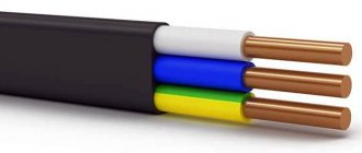
1.1. Requirements The instructions apply to collapsible and non-separable contact connections of busbars up to 15 mm thick, flexible busbars and profiles (channel, corvette, I-beam, etc.) made of aluminum, solid aluminum alloy AD31T and copper, as well as to the connection of busbars with terminals of electrical devices.
For contact connections of steel conductors, the requirements of the Instructions are recommended.
The instructions establish requirements for personnel performing design and installation work, determine organizational and technical measures to ensure the quality of electrical installation work and their safety.
1.2. This instruction is introduced by order of the organization and is mandatory for use in organizations of the Roselectromontazh Association.
TERMS AND DEFINITIONS
Terms mentioned in the Instructions
Document establishing the term
A method of tinning with simultaneous removal of an oxide film from a metal surface by friction with solid metal or non-metallic particles
Conductor connecting the grounded parts to the ground electrode
Contact unit forming a non-breaking contact
Linear contact connection
Contact connection of two or more conductors of current conductors, cables, overhead power lines, external control circuits, alarms, protection, etc.
Tinning by immersion in molten solder
Initial electrical resistance of the contact connection
Contact resistance measured immediately after assembly (before testing)
Permanent contact connection
A contact connection that cannot be opened without destroying it. For example, welded, soldered, riveted, etc.
Neutral protective conductor
Conductor connecting the neutral parts to the neutral of the electrical installation
Materials whose nominal electrochemical potentials are close in value
A current-carrying part intended for connecting current-carrying busbars made of dissimilar materials and connecting current-carrying busbars from one material to the terminals of electrical devices made of another material
Aluminum alloy plate
Hard Aluminum Alloy Adapter Plate
Adapter plate consisting of copper and aluminum parts
Demountable contact connection
A contact connection that can be opened without destroying it. For example, screw, bolt, etc.
3.1. Types of contact connections
3.1. 1. Connections between busbars made of homogeneous metals, branches from these busbars and connections of aluminum busbars and aluminum alloy busbars with terminals made of aluminum and aluminum alloys are made collapsible or non-dismountable. Connections of busbars made of dissimilar materials and in cases where operating conditions require periodic disassembly of the connections should, as a rule, be made collapsible.
The class of contact connections depending on their area of application is given in table. 3.1.
Class of contact connections depending on application
Recommended contact class
1. Contact connections of circuits whose conductor cross-sections are selected according to permissible long-term current loads (power electrical circuits, power lines, etc.)
2. Contact connections of circuits, the conductor cross-sections of which are selected for resistance to through currents, voltage loss and deviation, mechanical strength, and overload protection. Contact connections in circuits of grounding protective conductors made of steel.
3. Contact connections of circuits with electrical devices, the operation of which is associated with the release of a large amount of heat (heating elements, resistors)
Linear contact connections of power circuits should be classified as first class.
3.1.3. Depending on the climatic version and the category of placement of electrical devices in accordance with GOST 15150, contact connections in accordance with GOST 10434 are divided into groups A and B:
Climatic modification and category of electrical device placement
Contact group
Climatic versions U, UHL, TS for placement category UHL, TS for placement category 4 with atmosphere types II and I
Note: the table shows product placement categories
3.1.4. Contact connections must be made in accordance with the requirements of GOST 10434, GOST 17441, standards, technical specifications for specific types of electrical devices, SNiP 3.05.06-85, these instructions for working drawings approved in the prescribed manner.
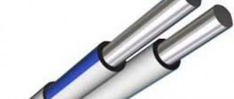
Connection - aluminum busbar
The connection of aluminum busbars to copper busbars is carried out using copper-clad aluminum adapter plates or copper-aluminum adapter plates.
In order to save copper, it is advisable to use aluminum clad adapter plates, in which one end is covered with a thin (fractions of a millimeter) layer of copper. The use of clad aluminum ensures a reliable connection between aluminum and copper with very low copper consumption. It is advisable to use clad plates when connecting buses of large sections. [1] The connection of aluminum busbars to copper busbars is made using copper-clad aluminum adapter plates or copper-aluminum adapter plates. In order to save copper, it is advisable to use clad aluminum transition plates, in which one end is covered with a thin (fractions of a millimeter) layer of copper. The use of clad aluminum ensures a reliable connection between aluminum and copper with very low copper consumption. It is advisable to use clad plates when connecting buses of large sections. [2]
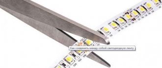
The connection of aluminum tires by pressure (cold welding) 1 is carried out with an overlap, while two counter punches are pressed into the connected tires (Fig. 11 - 26) from both sides, which ensures the solidity of the material structure at the points of contact of the tires. [3]
The connection of aluminum busbars by pressure is carried out with a cross section of up to 100X10 mm inclusive in all dry closed electrical installations of high and low voltage. Such busbar connections are not allowed in the busbars of generators, auxiliary switchgear of power plants, transformer chambers with a power of 20,000 kVA and above, and in installations subject to vibration. [4]
The connection of aluminum busbars to copper busbars is carried out using copper-clad aluminum adapter plates or copper-aluminum adapter plates. In order to save copper, it is advisable to use clad aluminum transition plates, in which one end is covered with a thin (fractions of a millimeter) layer of copper. The use of clad aluminum ensures a reliable connection between aluminum and copper with very low copper consumption. It is advisable to use clad plates when connecting buses of large sections. [5]
To connect aluminum busbars to each other and aluminum busbars to copper ones, as well as when connecting aluminum busbars and lugs to contact terminals of equipment, semi-clean bolts with a diameter of up to 10 mm with a normal hexagonal head are used, and with a diameter of 12 mm and above - semi-clean bolts with an enlarged hexagonal head. [7]
When connecting aluminum busbars, it is recommended to place special washers of larger sizes under the heads of the bolts and nuts, and when connecting aluminum busbars to copper busbars, use special washers only on the side of the aluminum busbar. If there are no oversized washers, install two normal washers instead of one special one. [8]
When connecting aluminum busbars, enlarged washers are placed under the holoicn and bolt nuts, and when connecting aluminum busbars to copper busbars or device terminals, the washer is placed only on the side of the aluminum busbar. [9]
Recently, welding has been widely used to connect aluminum busbars in switchgear. Such connections have high mechanical strength and good conductivity. However, for tires made of hardened aluminum alloys, in the weld zone, the material softens and the strength decreases to 50% of the nominal value. [eleven]
The characteristics of adapter plates for connecting aluminum busbars to copper ones, as well as methods for connecting busbars to the terminals of devices made of copper and copper alloys are indicated in Section. [12]
It is not recommended to use bolt clamps to connect aluminum busbars in open switchgear. [14]
Source www.ngpedia.ru
Connection of tires with bolts. Rectangular conductors are connected to each other using bolts, studs or clamps. The number of bolts is determined by the tire size. It is more expedient to ensure the compression force of the contact surfaces by using several bolts of a small cross-section, rather than one bolt of a larger cross-section, since in the first case the number of contact spots is greater. As a result, the contact resistance of the connection decreases and a more uniform distribution of current occurs over the contact area. Several parallel phase buses are connected to each other by laying them in a bind, and not in pairs, since in the latter case the contact surface is much smaller and the transition resistance is large. When electric current passes, the contact connections heat up and, as a result, expand. Particularly significant heating and expansion occur during a short circuit. The expansion is not the same throughout the connection, since its parts have different linear expansion coefficients. Bolts connecting copper and aluminum busbars operate under unfavorable conditions, since the coefficient of linear expansion of a steel bolt is less than that of a copper or aluminum busbar; in addition, the bolts always heat up significantly less than the busbars during a short circuit. In short-circuit mode, additional forces act on the bolts, which, when added to the tightening force of the bolt, can lead to residual deformations and weakening of the contact connection when the temperature drops. The thicker the busbar package, the greater the mechanical stress that occurs in the tie bolts. These stresses can be reduced if disc springs are installed under the heads of the bolts (nuts).
Disc springs for electrical purposes are manufactured (according to GOST 17279-71) of two types: Ш – to maintain contact pressure in busbar connections; K - to maintain contact pressure in connections of cable lugs with electrical equipment terminals that have a reduced contact surface compared to busbars.
Instead of disc springs, it is permissible to install a thickened washer under the bolt head or under the nut on the aluminum side, also to reduce stress. The length of the overlap (overlap) of the connected elements in a contact connection with one or four bolts rarely exceeds the width of the tire, and with two bolts it ranges from 1.5 to 2 times the width of the tire.
A decrease in the contact resistance of a connection is achieved by increasing the contact pressure and decreasing its rigidity. To reduce the rigidity of the contact connection, longitudinal cuts with a width of 3 ... 4 mm and a length of 50 mm are made on the tires.
The bolts in the connection are selected depending on the specific pressures between the contact surfaces, the apparent current density and the permissible tensile forces for the bolts. Recommended specific pressures in the combustor for various materials of contact connections are given below in table. 2.1.
The length of the bolts is selected such that after assembling and tightening the connections, at least two threads of free thread remain. The KS bolts are tightened with a wrench, ensuring the required torque values given in table. 2.2. The connection of aluminum busbars with busbars made of copper or aluminum alloys with a thickness of 4 mm, as well as copper or steel busbars with a thickness of 6 mm, can be made with M6 bolts 16 mm long or M8 bolts 20 mm long.
| | | next lecture ==> | |
| Connecting and terminating wires by soldering | | | Connecting wires to the terminals of machines and devices |
Date added: 2017-04-20; ; ORDER A WORK WRITING
Source helpiks.org
3.2. Requirements for permanent contact connections
3.2.1. Permanent contact connections are made by welding, soldering, crimping 1 or other methods specified in the current normative and technical documentation.
1 Permanent connections made by crimping or crimping methods are described in Chapter 7.
3.2.2. Structural elements and dimensions of welded contact connections of busbars should be selected in accordance with the recommendations of GOST 23792.
Main types of welded joints and tires
Methods for welding tires made of various materials are listed in table. 3.3.
Tire welding methods
aluminum alloy AD31
piece steel electrode
non-consumable tungsten electrode in argon
Semi-automatic and automatic with consumable electrode in argon
1) Welding AD31 alloy with a carbon electrode is not recommended
2) The following shielding gas is used: CO 2 or its mixtures
When choosing a welding method, keep in mind:
1) For welding with a carbon electrode, no special welding equipment is required, while for welding in a shielding gas (argon) environment with a consumable electrode, it is necessary to purchase a special semi-automatic welding machine, or an installation for manual argon arc welding. Due to its characteristics, carbon electrode welding is only possible in the lower position; welding in argon (manual and semi-automatic) can be performed in all spatial positions. When welding with a carbon electrode, the main factors that have a harmful effect on the welder’s body and the environment are ultraviolet radiation and the release of large amounts of welding aerosol and dust consisting of metal vapor, its oxides and flux combustion products. These emissions must be removed directly from the welding site and filtered before being released into the environment.
2) Manual argon arc welding with a tungsten electrode is effective for tire thicknesses up to 6 mm. At large thicknesses, the productivity of this method decreases sharply, especially at low air temperatures, which leads to a sharp increase in energy costs for welding. Welding in argon (manual arc with a non-consumable and consumable electrode) provides higher quality welded joints compared to welding with a carbon electrode. When welding in argon, the basis of harmful emissions is ozone, which also must be removed from the welding site.
4) Manual arc welding with coated electrodes is allowed to be used for connecting aluminum busbars with the seam in the lower position after agreement with the Customer or project developer.
Note: more detailed information about the choice of welding process, welding technique, and equipment can be found in the “Instructions for welding non-ferrous metals in electrical installation production.”
3.2.4. The surface of the seams of welded joints should be uniformly scaly without sagging. The seams should not have cracks, burns, lack of fusion longer than 10% of the seam length (but not more than 30 mm), unfused craters and undercuts with a depth of 0.1 of the tire thickness (but not more than 3 mm). Welded joints of expansion joints should not have undercuts or lack of penetration on the tapes of the main package.
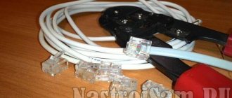
Proper Methods for Safe Connections in Electrical Wiring
Since the chemical properties of copper and aluminum are significantly different, standard techniques are not suitable for combining them. There is an opinion that it is generally not worth connecting of wires . Yes, standard twisting is categorically unacceptable here, but other methods that do not allow contact of conductors, but allow the full integration of copper and aluminum wiring, are perfect.
Bolted connection via bolt and steel washers
A method with a high degree of reliability is a bolted connection, which even a non-professional can do. In this case, direct contact, which is undesirable for copper with aluminum, conductors of different sections can be combined.
To connect aluminum and copper wires to each other in this way, you will need:
It is worth understanding that a knot made in this way will turn out to be quite cumbersome, which makes the method not always convenient. It is unlikely to be acceptable in a small apartment junction box, but it is perfect for a general electrical panel where there is enough space.
How to connect aluminum wires to copper using the bolt method:
1. Remove the insulation layer from the cables being connected;
2. Shape the stripped ends into the shape of a ring;
3. Install a washer, a ring of the first wire, a washer, a ring of the second, a washer, a nut, tightened until it stops;
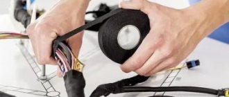
4. Apply insulation with tape.
Terminal adapters and terminal blocks
Another solution for how to properly connect copper and aluminum wires is the use of terminals and terminal blocks. They consist of a transparent plastic housing with cells and clamping screws, inside of which a brass sleeve is placed. With one block you can connect a different number of pairs of conductors by selecting the required number of cells.
How to use terminal blocks to connect wires:
1. Unscrew the clamp screw;
2. Remove the insulating layer from the conductor;
3. Insert the cable into the terminal and tighten the clamping screw.
The same is done by fastening the cable on each side.
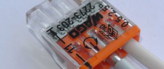
WAGO terminal blocks for aluminum and copper with paste inside (or without paste)
Terminals from the German brand WAGO are well known to electricians and enjoy a high level of trust. For cables made of one material, the company produces terminal models with flat spring clamps and equipped with clamping levers. To connect aluminum and copper, WAGO offers a variety of 2273 series terminals with contact paste inside.
Since the characteristics of copper and aluminum are different, direct contact between them is prohibited. To eliminate this, contact paste is needed inside the terminals.
It happens that terminal blocks are sold without paste.
In this case, such WAGO conductive paste for aluminum can always be purchased separately; it is called
WAGO “ALU-PLUS” art. 249-130
Alu-Plus contact paste from WAGO
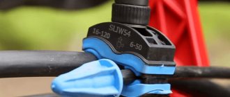
Method of crimping sleeves using press pliers: sleeves
Connecting wires by crimping with sleeves is a costly process, but it allows you to obtain a durable result, as well as reliable contact. You will need special sleeves that look like hollow tubes that act as a connector . Press pliers are also needed, which can be manual or mechanical.
The connection of copper and aluminum wires by crimping is carried out using combined sleeves. They are marked GMA, called aluminum-copper, and are designed for operating voltages up to 10 kV. Consumers are offered options available for different core cross-section sizes - 16/10, 25/16, 35/25, 50/35, 70/50, 95/70, 120/95, 150/120, 185/150, 240/185.
To perform the work:
1. The insulating layer is removed at the ends of the cable;
Connection with spring and self-clamping terminal blocks
Currently, both reusable and single-use terminal blocks and terminal blocks are produced.
Both reusable and single-use terminal blocks are produced in a wide range, including with a different number of connected wiring branches, designed to fix wires with a cross-section from 0.08 mm² to 6 mm². Including in the form of ready-to-install terminal boxes. This method of connecting aluminum and copper wires is currently the most optimal in terms of reliability and ease of use.
Terminal boxes with spring clamps were first produced by the German company Wago, from which they got their name, but currently there are a large number of analogues, including counterfeit ones. For this reason, it is necessary to purchase spring terminal boxes only from electrical stores. When purchasing terminal boxes on the market, there is a high probability of purchasing low-quality products that do not meet the stated requirements.
To fix the wires in the terminal box, it is necessary to prepare the wires; to do this, remove the insulation from their ends; the size of the exposed part must be at least 0.5 cm. After that, the open part of the cable core is inserted into the desired socket of the terminal box and fixed in it using a spring clamp or screw. It should be noted that mounting in a terminal box usually does not require additional insulation, but at the same time, when they are located in a wall, a distribution box is required. Thus, spring terminal blocks have a number of advantages over other types of connections due to ease of connection.
Why you can't connect copper and aluminum electrical wires directly
Aluminum and copper , when exposed to the external environment, form an oxide film on the surface. This does not pose a risk to copper, and in the case of aluminum it increases resistance.
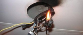
When aluminum and copper are in continuous contact, electrolysis begins. As a result, aluminum ions gradually transfer to copper, causing the first metal to gradually lose mass and voids appear in its structure. Since this reaction occurs continuously, at some point the aluminum is completely destroyed and the electrical wiring requires repair. The most dangerous consequence is overheating of the wiring and its fire.
Another reason why you can’t twist copper and aluminum wires is the discrepancy between their electrical conductivity. Aluminum is softer, its conductivity is lower, which makes it heat up more during contact. During the operation and rest of the wiring, expansion/contraction of the metals will constantly occur. This will gradually loosen the twist, which will increase the heat. This is another reason why you cannot connect copper and aluminum cable without using adapters.
Incorrect connection methods
Having listed the correct ways to connect copper and aluminum wires , one cannot fail to mention what should not be done during electrical installation.
Twist
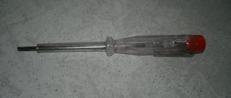
Twisted tinned copper wire
It is believed that if a copper conductor is tinned, its direct twisting with aluminum becomes possible. Opinions on this matter vary and most of them say that to connect copper wire to aluminum in this way. But there are still risks. The rules for tinning are simple and reliable only at first glance. Over time, the protective layer may begin to deteriorate, and it is almost impossible to control this process. better this method or use it only in the most extreme cases and for a short period of time.
Terminal blocks and terminal boxes
Convenient and reliable connection method. The terminal block is a strip of insulating material in which sockets for wires are located. The wires are fixed in the sockets using clamping bolts. An important feature in our case is the absence of contact between the wires. To connect copper and aluminum wires, you only need a screwdriver.
The terminal box is a system of several separately located terminal blocks, combined into one structure and having several terminals.
The advantages of this connection method are:
- Easy to install, all you need is an electrician's knife to strip the ends of the wire and a screwdriver to tighten the screws;
- Reliability of insulation, very often when using a terminal block or terminal box, additional insulation is not required;
- Undemanding to the length of the wire; 1–2 cm of wire is enough to fix the wire in the terminal box.
At the same time, to install hidden wiring in the wall, the terminal block requires the installation of a distribution box. Without a distribution box, installation of hidden wiring is unacceptable. But in this case, you can use a terminal box for flush mounting.
When working with the terminal box, it is important to carefully fix the ends of the wire in the socket, especially for aluminum wires. This is especially important when installing the box outdoors or indoors where temperature fluctuations are possible.
The simplest and most reliable connection between aluminum and copper wires
How to safely and correctly connect an aluminum conductor to copper and which adapter from one metal to another - on this matter, every electrical installation specialist has his own opinion, developed as a result of an analysis of work and personal experience. But most of them say that the simplest, most modern and safest method to connect copper and aluminum wiring is using WAGO terminal blocks with paste. They are safe for wires, and installation with them takes a minimum of time. In this case, the cheapest way is to use a bolt with a nut and washers to align the cables.
What methods to use to make the transition from aluminum to copper , everyone decides for himself.
Equality
Most often, all computers are equal to each other. Since there is only one communication channel, communication takes place in turns. Otherwise, due to sending messages at the same time, the signals may overlap each other, causing interference. This is why half-duplex mode is used in network cards.
Half-duplex is when transmission is carried out in only one direction, at one time and over one channel. Due to the fact that the bus typology does not have a central control unit in the form of a server or router, if one of the participants fails, the “Bus” will continue to operate.
You can also connect another computer at any time using a minimum of cable. But there is also a disadvantage that if the cables break, the network completely stops working. If such a network topology is very large, then repeaters are used between long cables.
A repeater is a device that amplifies and repeats a signal. Typically used in areas of signal attenuation in cable or wireless space (Wi-Fi).