Telpher connection
Electric hoists are a fairly common load-lifting equipment that has found wide application in various fields. However, for the effective and safe operation of such a device, it is very important to install it correctly. The process of connecting the mechanism to the electrical network plays an important role here. about typical hoist connection diagrams in this article.
Why is it so important to connect the hoist correctly?
Hoists are universal devices designed to move heavy objects along vertical and horizontal planes. There are quite a large number of different mechanisms of this type. We will not dwell in detail on each of them, since all this is described in the article “Types and design of hoists”. Let’s just say that models with electric drives have earned their popularity due to their ability to work in high-intensity mode, so they are advantageous to use in construction, as well as in various industries where it is necessary to constantly move heavy objects.
But for an electric hoist to work quickly and efficiently, it is very important to properly connect it to the power source.
It is worth noting: Failure to follow certain rules when connecting an electric hoist to the network can lead to complete breakdown of this mechanism, damage to the cargo, as well as harm to the life and health of people. As a result, only specially trained employees who have the necessary experience and skills are allowed to perform this task.
Device connection features
If you are interested in the connection diagram for a 220-volt hoist, or a model operating from an industrial electrical network (380 V), then, first of all, you need to read the operating instructions for such a device. It should contain all the necessary information on how to connect the hoist to power, as well as the control panel for this mechanism.
Before starting work, it is necessary to de-energize the equipment. Only after this can you begin installation. It is very important that the network and control cables are connected in accordance with the device connection diagram.
Hoist connection diagram
Regardless of whether you want to connect a single-phase hoist without a contactor, or any other model, the diagram is located on the side cover of the electrical panel. A copy of the diagram is also indicated in the lifting equipment passport. A typical circuit is shown in the figure below. It contains all the necessary information on how to connect the device and control panel to the electrical power source.
It is worth noting: Even for fairly similar devices, the circuits can differ significantly. Thus, it is necessary to follow the instructions for each specific mechanism. You should not purchase hoists that do not have a connection diagram. It is better to cooperate with trusted suppliers who can provide all the necessary documentation for their models.
How does installation work?
To connect the mechanism, a circuit breaker and fuses are used. Using the first device, you can interrupt an unloaded electrical circuit during work related to electrical wiring. Fuses prevent premature failure of the device in the event of power surges. It is best to place the fuse box in a hard-to-reach place so that others cannot use it. At the same time, working with the block should be simple and convenient.
Power is supplied to the electric hoist using four-core cables. It is important that one of the cores is grounded. In the case of trolley power, it is necessary that a fourth ground wire be present.
As a rule, a flexible cable in rubber insulation is used for the current conductor. If its length is no more than 25-30 meters, then the cable is suspended using rings on a string. This design is distinguished by its simplicity and ease of use. Its diagram is shown in the following figure.
For the string, brass or iron wire with a diameter of 5 millimeters is used. The diameter of the rings (indicated by numbers 3 and 4 in the figure) is 4 cm. It is important that the clamps (5) do not have sharp edges that could rub the cable. Additionally, the clamps are equipped with a tightening bolt (indicated by number 6). As a rule, a rubber pad (7) is used. The optimal distance between pendants is 140-180 centimeters. To prevent cable breakage, a soft metal cable with a diameter of about 2.5 millimeters is fixed at the clamping points. This way the tension will go through it, and not through the cable itself.
If the hoist moves at a distance of 30-50 m, then the cable should be suspended on a roller suspension. In the case when the electric hoist moves within a distance of more than 50 meters, it is necessary to install special high-quality conductive cables.
When using trolley power, it is worth using closed busbars or trolley routes.
It is worth noting: It is best to use cables with increased wear resistance, so they will last you much longer.
After connection, you should check the mains voltage (whether the data obtained corresponds to the parameters specified in the standard table). You can use the mechanisms only if all indicators are within normal limits.
Connecting a push-button post
When the device itself has been connected, it is necessary to check the functionality of the push-button station or remote control with a capacitor, with the help of which, as a rule, the hoist is controlled . To do this, press the lift button, and then observe the operation of the mechanism.
Important: if the connection is incorrect, it is possible that the load will begin to move downwards. There is nothing wrong with this, you just need to change the location of the connection points.
When all installation work is completed, you should check the integrity of the cables, as well as the possibility of de-energizing the hoist using the power switch. If mechanical or other damage is detected, operation of the equipment is strictly prohibited until all defects are eliminated.
Once again I would like to emphasize the importance of correctly connecting the hoist and the control panel to it. In the absence of special knowledge and skills, it is worth contacting a professional electrician for installation services, who can guarantee high-quality and uninterrupted operation of the hoist in the future.
Electrical Hoist Scheme
It is powered by direct current from the rectifier in the starting cabinet.
A copy of the diagram is attached by the manufacturer to the electric hoist passport. Additionally, hoists are supplied with two-speed motors - having two stator windings for operating speed and for precise positioning of the load. The hook suspension contains a freely rotating rope block in a metal casing that prevents the rope from falling off. Bulgarian hoists
Strangely enough, a bad electrician is one who doesn’t know this circuit, but there are such people. It is worth noting: Failure to follow certain rules when connecting an electric hoist to the network can lead to complete breakdown of this mechanism, damage to the cargo, as well as harm to the life and health of people.
The design of the lifting mechanism for a gear manual hoist is presented in the work. Drums 4 are located on both sides of the low-speed shaft 3. This is a high quality of manufacturing and assembly, high cost and limited capabilities for prompt service. For trolley power supply, a small-sized closed busbar or trolley route, designed according to the PUE, should be used.
There is no provision for reducing the control circuit voltage. Its advantages include: reliability and long service life of the equipment; high performance and wear resistance; fairly light weight of the structure; high level of security.
Electric winch. Review and modernization.
Electric hoist connection
Work on connecting an electric hoist (380V) in accordance with technical requirements can only be carried out by specially trained specialists.
Before starting work, the equipment is de-energized and only after that the network and control cables are connected in accordance with the connection diagram located on the side of the electrical panel cover. A copy of the diagram is attached by the manufacturer to the electric hoist passport. The device is connected to the power supply using a circuit breaker and fuses. The circuit breaker is designed to interrupt an unloaded electrical circuit when carrying out technical work on electrical wiring or mechanical components. It is recommended to place the circuit breaker and fuse block in hard-to-reach places, and work with it should be free and easy. Power cables must have increased resistance to mechanical damage. When connecting, it is necessary to check the compliance of the mains voltage specified in the standard table.
After connection, the buttons are checked for proper operation. To do this, press the “lift” button, and if the load moves down, you need to swap the connection points.
After installing the lifting equipment, it is necessary to check the integrity of the cables, the absence of damage to the mechanical components of the equipment and the possibility of de-energizing the hoist using the mains switch.
Let's consider the connection option using the example of a hoist produced by Balkansko Echo R. Bulgaria. Series T10, T39 Hoists of the T45, T78 series are connected in the same way
Electric hoist diagram.
Using the example of an electric hoist of the “T” series, as well as the power supply system to the hoists.
Current supply to hoists and hoists.
Basically, all used systems and types of power supply to lifting tools are devices that are designed for the safe and most optimal power supply. Main types:
Trolley current supply (current carrying rail systems). The main advantage of trolls is:
- feasibility of complex geometrically movable structures.
- high degree of protection (structurally, all electrical elements are placed inside an insulated housing). It is possible to use these systems in open areas and under a canopy.
- small voltage drops in the system, which has a beneficial effect on the service life of current-collecting equipment.
Cable trolleys (daisy chain systems). Carts are designed for efficient and safe movement of flexible cables from the power source to the consumption point during intensive use of electrical equipment. There are explosion-proof versions of the trolleys, which are indispensable in hazardous industries.
Self-winding cable reels .
Cable . Copper flexible cable suspended on brass or steel strings using rings. To ensure the safe use of such a connection, a flexible cable of shorter length is attached to the cable, which prevents rupture or tension in the current supply cable.
Kinematic diagram of the telpher
Which schematically shows the sequential transmission of motion from the engine to other working bodies and their relationship with each other.
Electrical Hoist Scheme
It is powered by direct current from the rectifier in the starting cabinet.
A copy of the diagram is attached by the manufacturer to the electric hoist passport. Additionally, hoists are supplied with two-speed motors - having two stator windings for operating speed and for precise positioning of the load. The hook suspension contains a freely rotating rope block in a metal casing that prevents the rope from falling off. Bulgarian hoists
Strangely enough, a bad electrician is one who doesn’t know this circuit, but there are such people. It is worth noting: Failure to follow certain rules when connecting an electric hoist to the network can lead to complete breakdown of this mechanism, damage to the cargo, as well as harm to the life and health of people. The design of the lifting mechanism for a gear manual hoist is presented in the work. Drums 4 are located on both sides of the low-speed shaft 3. This is a high quality of manufacturing and assembly, high cost and limited capabilities for prompt service. For trolley power supply, a small-sized closed busbar or trolley route, designed according to the PUE, should be used.
There is no provision for reducing the control circuit voltage. Its advantages include: reliability and long service life of the equipment; high performance and wear resistance; fairly light weight of the structure; high level of security. Electric winch. Review and modernization.
Possible connection diagrams for electric motor windings
Asynchronous electric motors have three windings, each of which has a beginning and an end and corresponds to its own phase. Winding designation systems may vary. In modern electric motors, a system has been adopted for designating windings U, V and W, and their terminals are designated by number 1 as the beginning of the winding and by number 2 as its end, that is, the U winding has two terminals: U1 and U2, the V winding has V1 and V2, and the W winding – W1 and W2.
However, old asynchronous motors made during the Soviet era and having the old Soviet marking system are still in operation. In them, the beginnings of the windings are designated C1, C2, C3, and the ends - C4, C5, C6. This means that the first winding has terminals C1 and C4, the second - C2 and C5, and the third - C3 and C6.
The windings of three-phase electric motors can be connected in two different patterns: star (Y) or delta (Δ).
Connecting an electric motor according to a star circuit
The name of the connection diagram is due to the fact that when the windings are connected according to this diagram (see figure on the right), visually it resembles a three-rayed star.
As can be seen from the electric motor connection diagram, all three windings are connected together at one end. With this connection (220/380 V network), a voltage of 220 V is applied to each winding separately, and a voltage of 380 V is applied to two windings connected in series.
The main advantage of connecting an electric motor according to a star circuit is the small starting currents, since the supply voltage of 380 V (phase-to-phase) is consumed by 2 windings at once, in contrast to the delta circuit. But with such a connection, the power of the powered electric motor is limited (mainly for economic reasons): usually relatively weak electric motors are turned on in a star.
Connecting an electric motor according to a triangle diagram
The name of this scheme also comes from the graphic image (see right picture):
As can be seen from the electric motor connection diagram - “triangle”, the windings are connected in series to each other: the end of the first winding is connected to the beginning of the second and so on.
That is, a voltage of 380 V will be applied to each winding (when using a 220/380 V network). In this case, more current flows through the windings; motors of higher power are usually switched on in a triangle than with a star connection (from 7.5 kW and above).
Connecting the electric motor to a three-phase 380 V network
The sequence of actions is as follows:
1.
First, let’s find out what voltage our network is designed for.
2.
Next, look at the plate that is on the electric motor, it may look like this (star Y / triangle Δ):
3.
After identifying the network parameters and the electrical connection parameters of the electric motor (star Y / delta Δ), we move on to the physical electrical connection of the electric motor.
4.
To turn on a three-phase electric motor, you need to simultaneously apply voltage to all 3 phases. A fairly common reason for electric motor failure is operation on two phases. This can happen due to a faulty starter, or due to phase imbalance (when the voltage in one of the phases is much less than in the other two). There are 2 ways to connect the electric motor: - using a circuit breaker or motor protection circuit breaker
When turned on, these devices supply voltage to all 3 phases at once.
We recommend installing a motor protection circuit breaker of the MS series, since it can be adjusted exactly to the operating current of the electric motor, and it will sensitively monitor its increase in the event of an overload. This device at the moment of starting makes it possible to work for some time at an increased (starting) current without turning off the engine. A conventional circuit breaker must be installed in excess of the rated current of the electric motor, taking into account the starting current (2-3 times higher than the rated current). Such a machine can turn off the engine only in the event of a short circuit or jamming, which often does not provide the necessary protection.
- using a starter
The starter is an electromechanical contactor that closes each phase with the corresponding motor winding. The contactor mechanism is driven by an electromagnet (solenoid).
Electromagnetic starter device:
The magnetic starter is quite simple and consists of the following parts:
(1) Electromagnet coil (2) Spring (3) Movable frame with contacts (4) for connecting power to the network (or windings) (5) Fixed contacts for connecting the windings of the electric motor (power network).
When power is supplied to the coil, the frame (3) with contacts (4) lowers and closes its contacts to the corresponding fixed contacts (5).
Typical diagram for connecting an electric motor using a starter:
When choosing a starter, you should pay attention to the supply voltage of the magnetic starter coil and buy it in accordance with the possibility of connecting to a specific network (for example, if you have only 3 wires and a 380 V network, then the coil should be taken at 380 V, if you have network is 220/380 V, then the coil can be 220 V).
5.
Check that the shaft is spinning in the right direction. If you need to change the direction of rotation of the electric motor shaft, then you just need to swap any 2 phases. This is especially important when powering centrifugal electric pumps that have a strictly defined direction of rotation of the impeller.
How to connect a float switch to a three-phase pump
From all of the above, it becomes clear that to control a three-phase pump motor in automatic mode using a float switch, you CANNOT simply break one phase, as is done with single-phase motors in a single-phase network.
The easiest way is to use a magnetic starter for automation. In this case, it is enough to integrate a float switch in series into the power supply circuit of the starter coil. When the float closes the circuit, the starter coil circuit will close and the electric motor will turn on; when it opens, the power to the electric motor will be turned off.
Classification
Can be performed according to the following parameters:
- Constructive. An electric hoist can serve a limited workplace (such as, for example, cantilever-rotary mechanisms), or it can serve a certain area along the route of its movement.
- Functional. The main indicators of the usefulness of a device are its load capacity, lifting height and length of movement of the load.
- Control method. In the cheapest electric hoists, mainly those with low load capacity, only the lifting of the load is controlled by the electric drive, and the movement (or rotation) of the device is performed by the operator.
Due to their compactness, ease of installation and reinstallation, as well as extreme ease of control, electric hoists are widely used in repair shops and warehouses. ONE HUNDRED. Individual posts of assembly lines of automobile assembly plants are equipped with cantilever-rotary devices, and autoloaders are equipped with mobile ones. By changing the type of gripping device, the electric hoist can be successfully adapted for loading scrap metal (grab devices), or used in large pharmacies to issue packaged blisters to the cashier's station.
The world's largest manufacturers of electric hoists are Bulgaria, China, Germany, and, of course, Russia. German electric hoists are distinguished by the same features as most types of industrial equipment that are produced in this country. These are high quality manufacturing and assembly, high cost and limited opportunities for prompt service. The quality of Chinese-made units is questionable and unstable, although this is compensated by dumping prices for products.
Excluding domestic ones, the most popular imported models of electric hoists are Bulgarian-made mechanisms. The corresponding products of the Bulgarian enterprise “BalkanCar” were well known and revered even during the times of the USSR. However, even now the former BalkanCar (under the Balkan Echo and ElMot brands) is considered a very reputable supplier of the equipment in question.
They are determined by the circuit by which the windings are connected.
"Star"
Such an electric motor is less efficient when connected to 220 V, since this connection of windings reduces the power by about 60 - 65%. But sometimes there is simply no choice.
"Triangle"
To connect to the 220 network, it is better to choose this option. Power will also be lost, but no more than half.
But connecting the windings is not everything. How many capacitors will need to be included in the circuit?
One - if the electric motor power does not exceed 1,500 W.
Two – at Pmot ˃ 1.5 kW.
Calculation of capacitor ratings
Legend: Sp – starting, Wed – working.
There are several simple formulas, but they will be of little use to the reader. Take my word for it.
Firstly, to carry out calculations, you will need to measure the current strength in any winding of the electric motor, and for this you will first have to connect it to a 3 ph network, and besides, use special clamps. But not everyone has them, even electricians. This applies to those engines in which the inscriptions on the nameplate are erased or there is no passport for the product. By the way, these types of samples are mainly used for homemade products - the used category.
Secondly, and most importantly, the author was convinced in practice that even an extremely accurate calculation is not a guarantee of the correct operation of the engine.
Thirdly, not everyone takes into account that calculations are made “under load”. At idle, the engine will begin to overheat. This once again proves that it is more expedient to select capacitors practically.
Finding the required capacity experimentally is the most correct solution. And this is not difficult to do if you know that for every 1000 W of an electric motor a capacitor of about 70 - 80 microfarads is needed. Place one or a whole assembly of several samples with different denominations - whatever is more convenient for you. Or rather, use what is at hand.
What to consider?
- For those who have forgotten school, the nominal values of the containers are added up when they are switched on in parallel. The sequential gives the sum of the reciprocals, that is, 1/C. This will help you choose the optimal value. The “trick” is that the industry produces capacitors designed for a certain capacity, and it is unlikely that it will be possible to find exactly the one required based on the calculation results (checked!). So you need to be prepared for the fact that you will have to experiment.
- The moment of switching on for an electric motor is the most “difficult”. Therefore, the value of the starting capacitor (Cp) should be equal to approximately three times the working capacitor (Cp). Otherwise there will be problems starting the engine.
Features of circuits and their assembly
- How to connect? Any three-phase electric motor has 3 wires that connect to its windings. The conductors can simply stick out from the housing or be inserted into the terminal box that is located on it. It doesn't matter. The diagrams clearly show what connects to what. The nuance is that the direction of rotation of the rotor cannot be guessed in advance. If the shaft rotates in the wrong direction, it is enough to swap the wires connected to the container.
- Acceleration button. It is held until the rotor reaches the nominal speed, that is, until the electric motor reaches the operating mode. You can also make it self-blocking and then automatically open the contacts. But this greatly complicates the diagram, so the author does not consider it advisable to provide any drawings. Those who are familiar with electrical engineering will either figure it out themselves or find the relevant information. The same applies to the organization of engine reversal. Sometimes it is necessary for its shaft to rotate in one direction or the other. The solution is to install a 3-pole switch.
- Insulation of container terminals. The voltage on them can reach high values. Before connecting the wire to the capacitor, a piece of PVC tube of the appropriate cross-section (the so-called cambric) should be placed on the conductor, and after fixing and reducing the temperature in the working area, “press” it onto the soldering site.
Recommendations
Do not forget that when the engine is turned on/off (especially when starting it) there may be significant voltage surges. Therefore, since it is connected to a 220 network, all capacitors involved in the circuit must be at least 400 V. This is the lower limit for voltage. But more (630, 750, and so on) - please; only their cost will be higher (if you have to buy).
All containers included in the circuit must be of the same type. Mostly paper capacitors are installed, and the author advises choosing them. Using electrolytic samples is possible, but this will require making special calculations and complicating the circuit. For example, by introducing diodes into it, placing containers under a protective casing.
If you do not have basic knowledge in the field of electrical engineering, then it is better not to experiment with the engine. You cannot use both paper and electrolytic capacitors at the same time in the same circuit!
Reversible circuit for connecting an electric motor through starters
In some cases, it is necessary to ensure that the motor rotates in both directions. For example, for the operation of a winch, in some other cases. A change in the direction of rotation occurs due to phase reversal - when connecting one of the starters, two phases must be swapped (for example, phases B and C). The circuit consists of two identical starters and a button block, which includes a common “Stop” button and two “Back” and “Forward” buttons.
Reversible diagram for connecting a three-phase motor through magnetic starters
To increase safety, a thermal relay has been added, through which two phases pass, the third is supplied directly, since protection in two is more than enough.
Starters can be with a 380 V or 220 V coil (indicated in the specifications on the cover). If it is 220 V, one of the phases (any) is supplied to the coil contacts, and “zero” from the panel is supplied to the second. If the coil is 380 V, any two phases are supplied to it.
Also note that the wire from the power button (right or left) is not fed directly to the coil, but through the permanently closed contacts of another starter. Contacts KM1 and KM2 are shown next to the starter coil. This creates an electrical interlock that prevents two contactors from being supplied with power at the same time.
Magnetic starter with a contact attachment installed on it
Since not all starters have normally closed contacts, you can take them by installing an additional block with contacts, which is also called a contact attachment. This attachment snaps into special holders; its contact groups work together with the groups of the main body.
The following video shows a diagram of connecting a magnetic starter with reverse on an old stand using old equipment, but the general procedure is clear.
When the SB1 button is pressed, power flows through the current relay, the normally closed limit switch contact and the KM2 starter contact, and turns on the KM1 starter electromagnet. The KM1 starter supplies power to the M1 motor, as a result of which the lifting of the load is turned on. A current relay (RT) is necessary to prevent prolonged operation of the engine in overload mode. The limit switch is necessary to stop rotation when the hook reaches the upper limit position in order to avoid damage to the winch or its drive. The power supply of the KM1 starter is passed through the normally closed contact of the KM2 starter to avoid their simultaneous activation. If this is not done, then if 2 starters are turned on at the same time, a short circuit will occur in the power part of the circuit at the contact areas of the contact groups, which will disable them. Such circuits for connecting starters to each other are called interlocking circuits.
In order to lower the load, press the SB2 button. When it is pressed, current flows through the normally closed contact of the limit switch of the lowest position. And the normally closed contact of the KM1 starter, passing through the coil of the KM2 starter, starts reverse rotation. The limit switch is necessary to avoid rewinding of the cable.
Schematic diagram of connecting the crane beam
Rice. 1. Connection diagram for electric hoists with a capacity of 5 tons
A standard example of connecting an electric hoist is the lifting mechanism of the Slutsk plant. The control circuit voltage is 42 V.
Equipment includes: disc brakes, standard and emergency switches in up and down positions.
Power is supplied to the electric motor and lifting units through a four-wire cable. One of the wires is used for grounding. This suggests that the trolley type of power supply is used for high-capacity cranes.
The voltage in the control circuit is 42 V, achieved through a transformer (T), which is also grounded. Fuses (F1-F3) protect the transformer windings. The key (S) supplies mains voltage to the starters. Movement is controlled using buttons S1-S4, which supply current to coils K1-K4.
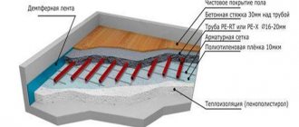
Connecting an electric boiler - electrical and hydraulic diagrams
Electric boilers are now installed quite often. But in most houses they serve only as a reserve. As a rule, the main ones are gas and solid fuel boilers, the operation of which is several times cheaper. But sometimes, with appropriate equipment, an electric boiler is used as the main one...
How is thermal energy from an electric boiler reduced in price? How to connect correctly, what circuit to use?
One of the most important advantages of this heat generator is known - better comfort and trouble-free operation, and then...
How much power will be required
How much power will be required to heat the house?
- It is known that for a well-insulated house you will need 10 kW per 100 sq. m.
- For houses built using energy-saving technologies, such power will be excessive.
- But if the box is characterized as “very cold”, then 20 kW will not be enough....
For an average house, the selection can be done exactly this way - 1 kW per 10 square meters. If in practice it turns out to be not enough, then it is economically feasible not to increase the power, but to insulate it - first change the windows and doors, then increase the layer of insulation in the attic...
Is an electric boiler suitable for constant heating?
From the point of view of convenience and reliability, the cost of repairs, an electric boiler is the best heat generator. The problem is the cost of electricity. It is not profitable to heat with it at a daily rate.
The second problem is the power allocated to the facility. Is it enough to fully heat the house?
It’s good if 15 kW of three-phase 380V power supply is allocated. Then you can install a boiler with a capacity of 12 kW, another 3 kW will be used for domestic needs.
But if the power supply is 220V and the permissible power of the boiler is only 4 kW, then it can only be considered as an emergency option to maintain heat in case the main one fails. Or for heating in the off-season, at a cheap rate, but such schemes will be discussed further...
We connect the electricity - so as not to catch fire
In order for the electric boiler to work without problems, first of all it must be correctly connected to the power supply. Different models have their own characteristics. But all factory units are equipped with an electrical circuit diagram and instructions. These documents are executed exactly.
The following remains common to all options.
- The use of cables of a certain type with copper conductors of the appropriate cross-section.
- Connection only with solid sections of cables, splices are not allowed.
- It is inadmissible to use automatic (VA) and other protection switches for constant switching on/off - if the boiler is not equipped with a switch, then such a device is installed additionally in the circuit.
- Application of electrical protection - ground leakage relay (Residual Current Device) and overcurrent protection (Automatic Circuit Breaker). These two devices can be combined in one housing and called a Differential Automatic.