First, you need to understand what a bus system and bus sections are separately, and then understand how a bus system differs from a bus section. At first glance, it seems that it is not difficult to find explanations for all the specialized terms, but it is much more difficult to understand the exceptions to the rules or the multifaceted use of busbar trunking of different types and categories. In this article we will try to recognize how a bus system differs from a bus section in more detail, focusing on the main technical characteristics and range of capabilities.
What is a bus system and why can there be confusion when identifying a power cable?
Initially, we will use the definition of “bus system” from the technical literature and understand that this concept means a special set of elements. These elements can be interconnected to form a functional power system. Absolutely all elements are connected to electrical distribution devices, and therefore are able to function uninterruptedly and as intended.
Important to remember! All existing switchgears at substations differ in nominal, that is, specified in technical documents, voltage level, as well as a certain power of generators and transformers. Each created network is designed for a certain power, operating mode and number of objects served.
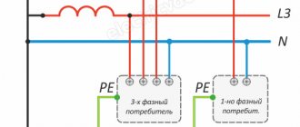
And if, for example, a potential customer needs to use switchgear with one bus system to implement a project, then the power equipment itself will contain a switch and two disconnectors. One is bus, and the second is linear.
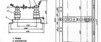
Among specialists, a synonym has been introduced for the concept of “busbar system” – “busbars”. And if a conversation comes up about them, then everyone understands that we are talking about a standard device, which is a well-thought-out system of busbars. And all elements of the system are fixed on special supports, while being protected by insulating material or special external boxes. Their installation takes place in specially designated rooms and technical corridors. The primary task of a busbar system or busbar system is to form an energy channel with the uninterrupted supply of the necessary power impulses to existing objects and branch lines.
Bus systems are necessarily tested before operation, that is, developers and manufacturers always routinely conduct type tests of bus systems and bus sections, and there is no difference in this.
If you plan to create outgoing connections to the bus system, then taps are used, through which new elements are powered.
Radial tire
The layers of cord in the tire frame do not intersect. They are made in the form of meridians - from one edge of the tire to the other. The point of contact with the road surface is reinforced with steel cord. This coating helps remove heat from the tire faster; it takes on most of the load. Thanks to it, the tread does not deform and the pattern remains constant.
pros
The frame threads experience only radial loads. This reduces the stress on them. This design feature makes it possible to reduce the ply structure of the carcass, better dissipate heat and make the tire lighter.
The use of a modular breaker with different types of cord improves traction characteristics. In this case, the shape of the tread does not change and the contact patch does not decrease.
Resistant to frontal punctures.
Minuses
The only drawback is considered to be weakness to side cuts. Since the number of threads in the carcass of radial tires is smaller and they are laid in the radial direction, they are easier to damage, unlike diagonal tires, where they intersect.
What is a double bus system and how is it formed by specialists?
Initially, imagine that specialists have created a bus system and it is functioning successfully. Then the need arises to expand the project and increase the power supply. Then experts can advise the customer to create a double bus system. It is usually created to provide redundancy for one bus system.
To install and complete a harmonious system, disconnectors, switches are used, additional switches organically complement the existing connections from the first system.
Sometimes it happens that in a dual system, one of the bus systems is made working, and the second - backup, that is, auxiliary, emergency, spare, in case it is necessary to increase the voltage supply, to resume the pulse supply. But most often at power substations, switching or connection of electrical circuits occurs in parallel, that is, one bus system is formed for some connections, and the second serves other areas.
What is a bus bypass system or how to live without force majeure situations?
Let's imagine a situation where one of the circuits was damaged or failures were noticed in the bus section, and the operation of the entire system was disrupted. The power equipment can no longer function normally, so it is necessary to carry out repair and maintenance work and perform circuit diagnostics. And in such force majeure cases, during the operation of bus sections and bus systems, the owners of objects with a bypass bus system remain the winner. What are its advantages?
- The bypass bus system ensures normal switching at substations when several systems are connected to switchgears, which operate either simultaneously or alternately.
- The bypass bus system provides adequate protection for bus sections and allows the system to be put into repair mode. This means that when one of the systems is switched off or fails, the backup connection is activated at the substation, that is, the bypass bus system comes into effect.
- The bypass bus system transfers into reserve not the existing two busbar systems, but the standard switches of any of the existing connections. And this is made possible by clever connections of the bypass system to each connection via a disconnector.
Thus, it becomes clearer what a bus system is. This concept is broad in the power system, since there are several types and types of bus systems, and all of them can be sectioned, that is, divided into sections of switchgear buses. And this property is very important and useful, since with bus segmentation it is possible to provide the substation with greater reliability. And when the degree of partitioning of the NKU is such that it makes it possible to isolate the damaged area in the bus system and carry out repair work, while leaving part of the connections in operation.
Application of bus bypass system
Switchgear circuits with one or two bus systems of all modifications have a common significant drawback, which is that the repair of switches or connection disconnectors is inevitably associated with an interruption in the work of consumers. At voltages of 110 kV and above, the duration of repair of circuit breakers, especially air circuit breakers, is so long that disconnecting connections often becomes unacceptable. The use of a bypass bus system allows you to eliminate this drawback. Below are examples of using bypass buses and how to connect them.
Switchgear circuit with one working and bypass bus system. The simplest version of such a scheme is obtained by adding a bypass system to a working non-sectional bus system (Fig. 1.12). The circuit includes the following elements: working bus system A1, bypass bus system AO, bypass switch QO, connection switches Ql, Q2, disconnectors QS1, QS2.
Any connection, for example W1, is connected to the working bus system A1 through the line disconnector QS2, switch Q1, bus disconnector QS1, and to the bypass bus system through the bypass disconnector QSO1. In normal mode, the operating bus system is energized. Bay switches, line and bus disconnectors are included.
The QO bypass switch and QSO1 bypass disconnectors are disabled, and the bypass disconnectors labeled on the QSO diagram are enabled. The bypass bus system is without voltage. During repairs or revisions of any linear switch, it can be replaced with a QO bypass switch.
For example, when replacing switch Q1, the following operations must be performed:
— turn on the QO bypass switch to check the serviceability of the bypass bus system;
— disable QO;
— turn on QSO1;
— enable QO;
— turn off switch Q1;
— disconnect disconnectors QS1 and QS2.
Rice. 1.12
Advantages of the scheme : disconnectors in all circuits are intended only to ensure the safety of repair work, which corresponds to their main purpose; possibility of inspection and testing of switches without interruption of operation; the simplicity of the scheme determines the low cost of implementing the switchgear.
Disadvantages of the scheme : in the event of a short circuit on the line, the corresponding switch must be turned off, and all other connections must remain in operation. However, if this switch fails, the power supply switches will trip.
A short circuit on the operating busbar system or on the busbar disconnectors also causes automatic shutdown of all power supplies. In both cases, the power supply to all consumers is stopped for the time necessary to repair the damage.
These disadvantages are eliminated by dividing the working bus system into sections and uniformly distributing power sources and outgoing lines between sections. In such switchgear circuits, a separate bypass switch is provided in the circuit of each section, or in order to save money, one bypass switch is used for both sections (Fig. 1.13).
Fig.1.13
This scheme consists of the following elements:
— working bus system A, sectioned by sectional switch QB into two sections 1VA and 2VA;
— bypass bus system;
— connection switches Q1,Q2;
— bypass switch QO;
— disconnectors QS1, QS2.
The QO bypass switch can be connected to any section using a split of two disconnectors QS3 and QS4. For example, with disconnector QS3 on and disconnector QS4 off, the bypass switch will be connected to the 1VA section.
The operating modes of the QB sectional switch depend on the type of electrical installation (power plant or substation) for which this switchgear circuit is intended. It should be noted here that the simultaneous activation of disconnectors QS3 and QS4 is unacceptable, since otherwise the sectional switch QB will be bypassed.
In this circuit, the bypass switch QO can also replace the switch of any connection, for example Q1, for which the following operations must be performed:
— turn off the QS4 disconnector (if it was turned on);
— turn on the QS3 disconnector (if it was turned off);
— briefly turn on the bypass switch QO to check the serviceability of the bypass bus system;
— turn on QSO1 and turn on QO;
— turn off switch Q1;
— disconnect disconnectors QS1 and QS2.
After these operations, line W1 will receive power through the bypass bus system and the QO switch from the first 1VA section (Fig. 1.14).
Sometimes the functions of bypass and sectional switches are combined (Fig. 1.15). Here the bypass switch QO is connected to the working sections through a jumper of two disconnectors QS1 and QS2. In normal mode, this jumper is turned on, the bypass switch is connected to the 2VA section and is also turned on.
Thus, sections 1VA and 2VA are connected to each other through QS4, QO, QSO, QS2, QS1, and the bypass switch performs the functions of a section switch. When replacing any line switch with a bypass switch, you must turn off the QO, turn off the QS2 jumper disconnect, and then use the QO for its intended purpose. In this case, for the entire time of repair of the linear switch, the parallel operation of the sections is disrupted.
Rice. 1.14 Fig. 1.15
Advantages of the scheme: in the event of a short circuit on busbars or in the event of a failure of linear switches, only 50% of all connections are lost during a short circuit on the line; possibility of inspections and testing of switches without interruption of operation; relative simplicity of the circuit and low cost of the switchgear.
The disadvantage of the scheme is that when repairing a working bus system, it is necessary to disconnect all power sources and outgoing lines.
The diagram (Fig. 1.15) can be used for substations (110 kV) with a number of connections up to six inclusive, when disruption of the parallel operation of the line is acceptable and there is no prospect for further development.
For a larger number of connections (more than 7), a circuit with separate bypass and sectional switches is recommended. This allows you to maintain parallel operation of lines during repairs of switches.
The considered schemes can be used for paired lines or lines backed up from other substations, as well as radial ones, but not more than one per section.
At power plants, it is possible to use a scheme with one sectional bus system, but with separate bypass switches for each section.
As already noted, in schemes with one working and bypass bus system, if it is necessary to repair the working bus system, all connections must be disconnected for the duration of the repair, which disrupts the power supply to consumers. The use of a scheme with two working and bypass bus systems eliminates this disadvantage.
The switchgear circuit with two working and bypass bus systems (Fig. 1.16) includes working bus systems A1 and A2, a bypass bus system AO, connection switches Ql, Q2,, bypass switch QO, bus connecting switch QA, disconnectors QS1, QS2, Each connection, for example W1, is connected to the operating bus systems via a fork consisting of two bus disconnectors QS1 and QS2, which allows operation on both one and the other bus systems.
As a rule, both bus systems are in operation with a corresponding fixed (uniform) distribution of all connections, for example connections with odd numbers are connected to the first working bus system A1, connections with even numbers are connected to the second working bus system A2. In normal operation, the bus coupling switch QA is closed, the bypass switch QO is open and the bypass bus system is de-energized.
QSO bypass disconnectors are disabled; The QO bypass switch is closed. This distribution of connections increases the reliability of the system, since in the event of a short circuit on the buses, the bus coupling switch QA is switched off and only half of the connections lose power. If the damage to the busbars is permanent, then the disconnected connections are transferred to a working busbar system.
Rice. 1.16
Advantages of a scheme with two working and bypass bus systems:
— there are conditions for inspections and testing of switches without interruption of operation;
— there is the possibility of rearranging connections between bus systems, which is necessary when changing the network diagram, system operating mode, etc.;
— the ability to repair any bus system while maintaining all connections.
Disadvantages of this scheme:
— failure of one switch during an accident leads to the disconnection of all power sources and lines connected to a given bus system, and if one bus system is in operation, all connections are disconnected;
— damage to the bus coupling switch is equivalent to a short circuit on both bus systems, that is, it leads to the disconnection of all connections;
— a large number of operations with disconnectors during inspection and repair of switches complicates the operation of the switchgear.
Some increase in circuit flexibility and reliability can be achieved by partitioning one or both bus systems (Fig. 1.17). Both operating bus systems are in operation with a fixed distribution of connections between sections. Bus coupling switches QA1 and QA2 are switched on. Bypass switches QO1 and QO2 are disabled. The bypass bus system is without voltage. The state of sectional switches QB1 and QB2 is determined by the type of electrical installation in which this switchgear circuit is used.
Rice. 1.17. Scheme with two partitioned working and bypass bus systems
In this switchgear circuit, in the event of a fault on the busbars or a short circuit in the line and failure of the line switch, only 25% of the connections are lost (during the switching period); in the event of a fault in the bus connecting switch, 50% of the connections are lost. If the busbars are sectioned, then to reduce capital costs it is possible to use a circuit where the busbar and bypass switches are combined.
In normal mode, disconnector QS2 is disabled, disconnectors QS1, QSO, QS3 are on, the bypass switch acts as a bus coupling switch. If it is necessary to repair the switch of any connection, for example W1, switch off switch QOA1 and disconnector QS3 and use the switch for its intended purpose. In circuits with a large number of lines, the number of such switchings is significant, which leads to complications in operation, therefore there is a tendency to abandon the combination of bus connecting and bypass switches.
RUs made according to a scheme with two working and bypass bus systems are used at power plants and substations at a voltage of 110-220 kV. At stations with a number of connections of 12-14, one bus system is sectioned; with a larger number of connections, both bus systems are sectioned. At substations, one bus system is sectioned at a voltage of 220 kV and the number of connections is 12-15 or when transformers with a capacity of 125 MVA or more are installed; at voltages of 110-220 kV, both systems are sectioned with more than 15 connections.
At voltages of 330 kV and higher, the use of circuits with two working and bypass bus systems is impractical, since disconnectors in such circuits are used as operational devices. A large number of operations with disconnectors and complex interlocking between switches and disconnectors lead to the possibility of erroneous switching off of the load current by disconnectors. In addition, the need to install busbar, bypass switches and a large number of disconnectors increases the cost of switchgear construction.
What are busbar sections and how important are they for the functioning of busbar trunking?
In the technical literature there is a definition of “bus sections”, and it reads as follows: bus sections are certain parts of the bus system, separated from each other by switching devices. Existing GOSTs specify various types of partitioning. And most often there are six typical forms of sectioning, namely:
- Bus systems without internal separation, when the main bus, input and output functional blocks, distribution buses function as one system, are not divided into blocks by partitions or barriers.
- Busbar systems with separation of busbars and functional units, but the terminals for external conductors from the busbars are not separated by barriers made of metal or plastic.
- Segmentation of buses and functional units with clamps of external conductors.
- Separation of functional units from each other, as well as from existing buses. Additionally, barriers separate the terminals of external conductors from the blocks, but they remain connected to the buses.
- Separation of all functional units present in the system from each other, as well as from the buses. The terminals of external conductors are located in one block, therefore they are separated from both busbars and functional units. With this segmentation, it is easy to test the busbar section, repair it and put it into operation.
- Bus system, when functional units are located in the same compartment with the terminals of external conductors.
Thus, there are six types of segmentation, when different options for insulation and interaction of the main bus, functional blocks, distribution buses, and terminals for outgoing conductors appear. With any configuration, the tire system is operational.
Single sectional busbar system
The diagram shown in Fig. 4.5, retains all the advantages of the circuit with a single busbar, in addition, an accident on the busbars leads to the disconnection of only one source and half of the consumers; the second section and all connections to it remain in operation. Let's consider the advantages of this scheme. In the event of a short circuit on the busbars (at point K
1) switch
Q
3 and section switch
QB
2 will turn off, i.e.
There will be a cessation of power supply to consumers connected to the busbar system B
1.
In the event of a short circuit at the connection, for example, at point K
2 switch
Q
5 should turn off, and all other connections should remain in operation.
However, if this switch fails, the power supply switch Q
3 and the section switch
QB
2 will turn off, as a result of which busbars
B
1 will remain without voltage.
In case of a short circuit at point K
3, switches
Q
1,
Q
3 are turned off and power is supplied to the first section of busbars
B
1 through the sectional switch
QB 2
from the second section of busbars
B
2. When one power source is disconnected, the remaining power supply takes over the load.
Thus, the power supply to consumer TPs in emergency modes is not disrupted due to the presence of redundant supply lines, for example, W
1 and
W
3, connected to different sections of consumer TPs, each of which must be designed for full load (100% power reserve across the network).
The scheme can be recommended for feeding responsible consumers.
The disadvantages of this scheme are the following:
‒ in case of damage and subsequent repair of one section, critical consumers are left without backup, and consumers not backed up via the network are disconnected for the entire repair period (for example, connected to non-redundant lines W
1 and
W
4);
‒ the power source connected to the section being repaired is turned off for the entire repair period.
In the considered circuit, sectional switch QB
1 is on during normal operation.
This mode is usually used at power plants to ensure parallel operation of generators, and at transformer substations to switch on transformers for parallel operation. On the SPP, sectional switch QB
2 is usually turned off in normal operation in order to limit short-circuit currents.
The circuit is quite reliable and is widely used to power the own needs of transformer substations, where its advantages can be fully used, especially thanks to the use of switchgear.
Double busbar system
The desire to further increase the flexibility and reliability of the main circuits of stations and substations led to the use of a double busbar system (DBS).
In Fig. 4.6. The diagram of a double non-sectional SSSH is presented with the connection of each connection through two bus disconnectors (SB) and one switch.
Why is it recommended to perform tire segmentation and why can’t you do without it?
Partitions or metal barriers are used to separate the main elements of the bus system. They are necessary to increase the safety of personnel who service the power system and to localize unwanted processes.
With correct segmentation, repair work will not stop the process; all forms of partitioning of the switchgear allow everything to be restored quickly, without stopping the system.
Thus, the bypass bus section allows you to create a decent functioning busbar system that is easy to install and maintain, that is, carry out technical inspections, testing, and repair work on time. As a result, it becomes clear that a bus system is a set of busbars, which, for optimization, are best segmented in order to improve the process of supplying an energy pulse when servicing several power lines or objects.