Current transformer design One of the requirements when selecting current transformers (CTs) is their design check for a 10% error.
What does this mean and what is it for? This means that in emergency mode, when the current in the primary winding of the current transformer reaches a certain calculated value, the CT error should not exceed 10%. Otherwise, the current in the secondary winding of the current transformer will differ by more than 10% from the primary (taking into account the transformation ratio), which may lead to failure of the protection.
There are several ways to check a CT for a 10% error:
- According to the maximum multiplicity curves
- According to TT passport data
- According to the actual current-voltage characteristics taken from the CT before turning on the electrical installation
- According to the typical magnetization curve of electrical steel used for the manufacture of transformer transformers.
All these methods are described in the books of Shabad M.A. We will dwell in detail on the method of checking a current transformer using its passport data. Why on it? Because at the design stage of an electrical installation it is not possible to measure the actual current-voltage characteristics of a transformer, it is also quite problematic to obtain maximum factor curves from CT manufacturers, not to mention the magnetization curve of the electrical steel from which the CT core is made.
There are two ways to check a TT for a 10% error according to its passport data:
- Based on the known passport data of the CT and its load, the actual maximum multiplicity factor Kpk.fact is determined and compared with the minimum required Kpk.min
- The minimum required maximum multiplicity factor Kpk.min is determined, and then, taking into account the actual secondary load of the CT, the nominal Kpk.nom is determined. Then the current transformer with the nearest larger standard value of the coefficient Kpk.nom is selected
Let's consider the first option in more detail (determining the actual Kpk.fact and comparing it with the minimum required Kpk.min).
Determination of the actual coefficient of the maximum multiplicity Kpk.fact
So, to determine the actual limiting multiplicity coefficient Kpk.fact, the following initial data are required:
a) TT passport data, namely
- Snom — rated secondary load of the current transformer, VA;
- Ztr is the internal resistance of the current transformer, Ohm;
- Kpk.nom – nominal limiting factor;
- Ifirst is the primary rated current of the current transformer, A;
- Isecond is the secondary rated current of the current transformer, A.
b) The connection diagram of the current transformers and secondary load must be known
c) It is necessary to know which devices are connected to the secondary winding of the CT, as well as with which wires this connection is made.
Now it is necessary to determine the value of the secondary load connected to the CT circuits. To do this, we will use ready-made formulas borrowed from the book of Shabad M.A.
Table 1 – Calculation formulas for determining the secondary load of current transformers Zn.calc.
It is clear that in the formulas Zn.calc is the calculated value of the secondary load connected to the CT circuits; rpr – resistance of the wires connecting the current transformer and the protection relay; rper – transition resistance. Taken equal to 0.1 Ohm; Zr, Zr.f, Zr.rev – relay resistance.
Since microprocessor-based protection relays are now mainly used, their power consumption through current circuits is very small. Therefore, in the formulas, instead of Zр, Zр.ф, Zр.орр we substitute the value of power consumption for the current circuits of the microprocessor relay (in Ohms). If in each phase and in the neutral return wire its own separate relay is installed, then the value of the power consumption of each relay must be substituted into the formulas.
If in the information on the relay the power consumed by current circuits is given in W or VA, conversion to Ohms is carried out using the formula
Zр(Ohm) = Sp(W) / I 2first
Similarly, the rated power of a current transformer is converted from VA to Ohms
Znom.tt (Ohm) = Snom.tt (VA) / I 2first
Wire resistance rpr is calculated using the formula
rpr = Lpr / (γpr · Spr), Ohm
where: Lpr – length of wires from the CT terminals to the relay, m Spr – wire cross-section, mm2; γpr – specific electrical resistance, depending on the wire material
- γpr = 57 m/Ohm mm2 – for copper
- γpr = 34.5 m/Ohm mm2 – for aluminum
Now it is necessary to determine the actual limiting factor using the formula
Testing instrument transformers
Checking current transformers
When switching on again, the current transformers and their circuits are inspected, the DC resistance and electrical strength of the insulation of the secondary windings are checked, unipolar terminals are determined, the magnetization characteristics and transformation ratios are checked. During routine checks, current transformers are inspected, winding resistance, insulation resistance are checked, and magnetization characteristics are taken. If the built-in current transformers are removed during testing, it is necessary to additionally check the polarity of the windings and the transformation ratios on different taps. The polarity of the terminals of the current transformer windings is checked using a magnetoelectric device with the polarity of the winding indicated and zero in the middle of the scale according to the diagram shown in Figure 1. A direct current source, which is used as an electric battery B or a 4-6 V battery, is connected in series with the additional resistance Rd to the primary winding of the current transformer. In this case, the positive pole of the battery is connected to the “beginning”, and the negative pole to the “end” of the primary winding.
Figure 1 – Determination of the polarity of the current transformer windings.
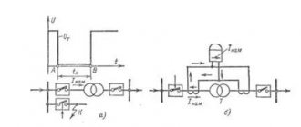
By closing and opening the circuit of the primary winding of the current transformer with key K, observe the deflection of the needle of the magnetoelectric device connected to the secondary winding. If, when the primary circuit is closed, the arrow of the device deviates to the right, and when it opens, to the left, it means that the terminals of the primary and secondary windings of the current transformer, to which the plus of the battery and the plus of the device are connected, are unipolar. To increase the deflection of the arrow of the device used in the testing circuit, you can change the value of the additional resistance, as well as the battery voltage. The magnetization characteristic, which represents the dependence of the voltage at the terminals of the secondary winding of the current transformer on the magnetizing current, is the main characteristic by which the serviceability of the current transformer can be determined, as well as the possibility of its use in various relay protection schemes. To remove the magnetization characteristic when the primary winding is open, an alternating voltage is supplied to the terminals of the secondary winding of the current transformer through a regulating autotransformer AT (Figure 2).
Figure 2 – Removing the magnetization characteristics of the current transformer.
By increasing the voltage supplied to the secondary winding, several values of voltage and current are recorded. When switching on again, 10-12 points are removed in this way, from which the magnetization characteristic is constructed (Figure 3). During routine checks of current transformers, three or four points are taken and the coincidence with the characteristic taken earlier is checked. It is advisable to remove the magnetization characteristic until saturation, i.e., to such values when the current transformer saturates and the magnetization characteristic bends. Measurement of current and voltage when taking the magnetization characteristic should be carried out using devices of an electromagnetic or electrodynamic system that respond to the effective values of the measured quantities. Before and after checking the magnetization characteristics, the core is demagnetized by two or three smooth increases and decreases in voltage to zero. In the presence of short-circuited turns in the secondary winding of a current transformer, its magnetization characteristic decreases, as shown in Figure 3, which can be detected by comparing the obtained characteristic with the characteristic taken earlier, or with the characteristics of current transformers of the same type. The most obvious difference in characteristics in the presence of short-circuited turns is manifested in their initial part at magnetizing currents of 0.1-1 A.
Figure 3 – Magnetization characteristics of current transformers. 1 - serviceable; 2 - with shorted turns.
Figure 4 – Scheme for measuring the magnetization characteristics of current transformers with a secondary current of 1 A.
For some types of current transformers, the saturation of which occurs at high voltage values (for example, 400-600 V), a special test circuit is required that allows the characteristic to be taken before saturation begins. Such a circuit, which is used to take the magnetization characteristics of current transformers with a secondary rated current of 1 A, is shown in Figure 4. In this circuit, a special transformer T for a voltage of 220/2000 V is used to increase the voltage supplied to the terminals of the secondary winding of the current transformer. In this case, you should not apply too high voltages to the secondary winding, since this is dangerous for the interturn insulation. Therefore, it is recommended to apply such a voltage to the secondary winding of one-amp current transformers that there is no more than 1-1.2 V per turn of the secondary winding. The magnetization characteristic can also be removed when current is supplied to the primary winding, as shown in Figure 5. Current into the primary winding The current transformer is supplied through an intermediate transformer T 220/12 V, with a power of 500-600 VA, its value is regulated by an autotransformer AT. The voltage on the magnetizing branch is measured using a voltmeter V connected to the terminals of the secondary winding. The voltmeter must have a high internal resistance of 1.5-2 kOhm/V and a measurement range of 10-2,000 V. Taking the magnetization characteristic when applying current to the primary winding of a current transformer is especially convenient when checking one-amp current transformers, when there is no special device for supplying a sufficiently large voltage to the terminals of the secondary winding.
Figure 5 – Removing the magnetization characteristics when current is supplied to the primary winding of the current transformer.
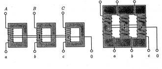
Figure 6 – Schematic diagram of cascade current transformers.
In installations with voltages of 500 kV and above, cascade current transformers are used, the diagram of which is shown in Figure 6. A feature of testing such current transformers is that each stage of the cascade must be checked separately. Then, after connecting both stages, the magnetization characteristic of each current transformer winding in the complete circuit is checked. For built-in current transformers, the magnetization characteristic should be measured twice: before inserting the current transformer into the bushing to check its serviceability and. after installing the bushing together with the current transformer in place. In this case, the magnetization characteristic can be measured only on one of the taps. The magnetization characteristic for other taps of the built-in current transformer will be determined by recalculation using the following formulas: where U, Inam, w - voltage, magnetizing current and the number of winding turns for the branch on which the magnetization characteristic was taken; U', I'us, w' - voltage, magnetizing current and number of winding turns for the branch for which the characteristics are recalculated.
Figure 7 – Determination of the current transformer transformation ratio.
Figure 8 – Definition of branches of the built-in current transformer.
The transformation ratio of the current transformer is checked according to the diagram shown in Figure 7. A current of at least 20% of the rated current is supplied to the primary winding from the load transformer NT. The current transformer ratio is defined as the ratio of the primary current I1 to the secondary current I2 and is compared with its rated value. For built-in current transformers, it is necessary to check the transformation ratios for all branches and the correct marking of the branches. Checking the correctness of the branch marking can be done when determining the transformation ratios or in another simpler way.
Figure 9 - To determine the winding branches of the built-in current transformer 600/5.
To do this, an alternating voltage is supplied to any two branches of the secondary winding through an autotransformer (Figure 8). By measuring the voltage between each pair of branches, the maximum voltage value is used to determine the terminals corresponding to the maximum transformation ratio A and D. After these terminals are found, they are supplied with voltage from the autotransformer AT. Then the voltage distribution along the winding of the current transformer is checked by measuring the voltage between one of the terminals, for example A, and all other branches. The lowest voltage corresponds to the branch with the lowest transformation ratio. Other branches are found in the same way, comparing the measurement results with the factory diagram of the distribution of turns between the branches.
Checking voltage transformers
When switching on again, the voltage transformer and its secondary circuits are inspected, the electrical strength of the insulation, the polarity of the windings and the marking of the secondary circuits are checked, the short circuit voltage and the resistance of the DC windings are measured, the serviceability of the secondary voltage circuits and the reliability of the fuses and circuit breakers are checked, as well as control and signaling circuits in case of damage. During scheduled inspections, which are carried out once every 3-4 years and are combined with a major overhaul of the voltage transformer, an inspection is carried out, the electrical strength of the insulation, the serviceability of the protection and control devices of the voltage circuits are checked. After repairs involving disconnecting the windings from the terminals, the unipolar terminals are checked. Determination of the polarity of the windings of a voltage transformer is carried out according to the same scheme as for current transformers. The DC source is connected to the high voltage winding, and the device is connected to the low voltage winding.
Figure 10 – Determination of voltage transformer short circuit voltage
Some features differ in checking the polarity of the terminals of a three-phase voltage transformer, which does not have a zero terminal of the primary winding. Therefore, the terminals of the DC battery in this case are connected to the terminals of the two phases of the highest voltage, and the device is connected to the zero and phase terminals of the low voltage winding. Moreover, if the windings of the voltage transformer are connected according to the Y/Y-12 circuit, the arrow of the device will deviate to the right when the DC circuit is closed, when the positive terminal of the device is connected to the phase whose higher voltage terminal is supplied with plus DC batteries. The magnitude of the short circuit voltage, which is necessary to determine the internal resistance of the voltage transformer, is measured according to the circuit shown in Figure 10. The voltage applied to the terminals of the low voltage winding is gradually increased until the current reaches the rated value. The short circuit voltage will be equal to: and the resistance of the voltage transformer, reduced to the low voltage side (Ohm): where UH is the rated voltage on the low voltage side of the VT; Uk is the voltage on the low voltage side, measured during a short circuit experiment, when the current in the low voltage winding was equal to the rated one.
Figure 11 – Determination of the voltage transformer transformation ratio. a - direct measurement; b - comparison method; c - additional winding of a five-rod voltage transformer.
For three-winding voltage transformers having two low-voltage windings, it is necessary to measure three IR values, as for a three-winding power transformer (between the high-voltage winding and each low-voltage winding, as well as between two low-voltage windings). For all voltage transformers, the transformation ratio is checked when switched on again. The transformation ratio of voltage transformers with a rated primary voltage of up to 10 kV is checked according to the diagram in Figure 11, and when an alternating voltage of 220-380 V is applied to the primary winding. For voltage transformers of 35 kV and above, determining the transformation ratio according to the diagram in Figure 11 is difficult due to low voltage on the low voltage side. In such cases, to determine the transformation coefficient, it is advisable to use the comparison scheme shown in Figure 11, b. In this case, the higher voltage windings of the two tested single-phase voltage transformers are connected in parallel, and a voltage of 50-60 V is applied to the low voltage winding of one of them. The voltages measured at the terminals of the low voltage windings must be equal if the transformation ratios of both voltage transformers are equal. Figure 11, c shows a diagram for measuring the transformation ratio of the additional winding of a five-rod transformer. In this circuit, voltage is applied to the terminals of two phases of the higher voltage side, and the winding of the third phase is shunted, which is necessary for correctly determining the transformation ratio. For all voltage transformers, the magnetizing current is measured when the rated voltage is applied to the low voltage winding. It should be borne in mind that the magnetizing current of voltage transformers of 110 kV and above reaches 10 A and above, as a result of which a sufficiently powerful power source is required for testing. Since current or voltage curves can be greatly distorted, when switching on again and during routine checks, the magnetizing current should be measured using the same circuit, using a potentiometer or autotransformer. Using different circuits may result in significantly different measurements. Measuring the magnetizing current should be done quickly, since the secondary windings are not designed to carry such large currents for a long time. When measuring the magnetizing current of voltage transformers, safety precautions must be strictly observed, since the high voltage side is under high voltage. When checking voltage transformers, the circuit breakers and fuses installed in their secondary circuits to protect against short circuits are checked.
Determination of the minimum required limiting factor Kpk.min
All current transformers used to power relay protection and automation equipment must ensure accurate operation of the measuring protection elements in specific design conditions, for which the total error of the current transformers should not exceed 10% at I1calc.
In the general case, the minimum required limiting factor Kpk.min is determined by the formula:
Kpk.min ≥ Ktd I1calc / Iprimary tt
where: Ktd - transition dimensional coefficient;
I1calc is the current at which the CT operation must be ensured with an error of less than 10% for the correct functioning of the relay protection. The values of I1calc are different for different types of protection;
Iprim.tt – rated primary current of the CT.
Note: microprocessor devices may have their own requirements for Kpk.min. Thus, for Siemens devices of type 7SJ80, 7SJ81, 7SJ82, the minimum required limiting factor must be Kpk.min ≥ 20.
Table - Determination of the minimum required limiting factor Kpk.min
| Type of protection | To td | I 1calc | Note | |
| MTZ and TO | Independent time-current system | 1,1 | I triggered - the operating current of the highest current stage (usually the current cut-off) | K pc.min ≥ 20 (for Siemens types 7SJ80, 7SJ81, 7SJ82) /td> |
| Dependent time-current x-ka | 1,1 | I trip.MTZ.set - current at which the steady-state (independent) part of the characteristic begins | ||
| DZSh | 0,5 | I short circuit max – maximum short circuit current at the protection installation location | ||
| DZT | Short circuit inside the protected area | 0,5 | I internal short-circuit – maximum short-circuit current in case of fault inside the protected area | Kp.min ≥ 25 (for Siemens type 7UT82, 7UT85) |
| Short circuit outside the protected area | 2 | I external short-circuit – maximum short-circuit current in case of fault outside the protected area (referred to the HV side) | ||
| DZL (line differential protection function 87L) | Short circuit on the protected line | 0,5 | I internal short-circuit – maximum short-circuit current in case of fault on the protected line | For Siemens type 7SD82 |
| Short circuit outside the protected line | 1,2 | I external short-circuit – maximum short-circuit current in case of fault outside the protected line | ||
Where:
- MTZ and TO – maximum current protection and current cut-off;
- ДЗШ – differential bus protection;
- DZT – transformer differential protection;
- DZL – differential line protection
How to check a current transformer
Devices that proportionally convert alternating current from one quantity to another based on the principles of electromagnetic induction are called current transformers (CTs).
They are widely used in the energy sector and are made in different designs, from small models placed on electronic boards to meter-long structures installed on reinforced concrete supports. The purpose of the test is to identify the performance of the CT without assessing the metrological characteristics that determine the accuracy class and angular phase shift between the primary and secondary current vectors.
Possible faults
. Transformers are made as autonomous devices in an insulated housing with leads for connection to primary equipment and secondary devices. Below are the main causes of malfunctions:
— damage to the housing insulation; — damage to the magnetic circuit; — damage to the windings: — breaks; — deterioration of conductor insulation, creating interturn short circuits; — mechanical wear of contacts and leads.
Test methods
. To assess the condition of the CT, a visual inspection and electrical tests are carried out.
Visual external inspection
. It is carried out first and allows you to evaluate:
— cleanliness of the external surfaces of parts; — the appearance of chips on the insulation; — condition of terminal blocks and bolted connections for connecting windings; — presence of external defects.
Insulation check
. (operation of CTs with damaged insulation is not allowed!).
Insulation tests
. On high-voltage equipment, the current transformer is mounted as part of the load line, enters it structurally and is subjected to joint high-voltage testing of the outgoing line by insulation service specialists. Based on the test results, the equipment is allowed into operation.
Checking the insulation condition
. Assembled current circuits with an insulation value of 1 mOhm are allowed for operation.
To measure it, a megohmmeter with an output voltage that meets the requirements of the CT documentation is used. Most high voltage devices should be tested with a 1000 volt output meter.
So, a megohmmeter measures the insulation resistance between:
- housing and all windings; - each winding and all the others.
The performance of a current transformer can be assessed by direct and indirect methods.
1. Direct verification method
This is perhaps the most proven method, which is also called checking the circuit under load.
A standard CT switching circuit is used in the circuits of primary and secondary equipment, or a new test circuit is assembled, in which a current from (0.2 to 1.0) of the rated value is passed through the primary winding of the transformer and measured in the secondary.
The numerical expression of the primary current is divided by the measured current in the secondary winding. The resulting expression determines the transformation coefficient and is compared with the passport data, which allows us to judge the serviceability of the equipment.
A CT may contain several secondary windings. All of them, before testing, must be reliably connected to the load or short-circuited. In an open secondary winding (with current in the primary), a high voltage of several kilovolts arises, dangerous to humans and equipment.
The magnetic cores of many high-voltage transformers require grounding. For this purpose, a special clamp marked with the letter “Z” is equipped in their terminal box.
In practice, there are often restrictions on testing CTs under load related to operating and safety conditions. Therefore, other methods are used.
2. Indirect methods
Each method provides some information about the state of the CT. Therefore, they should be used in combination.
Determining the reliability of winding terminal markings
. The integrity of the windings and their output is determined by “continuity testing” (measuring ohmic active resistances) with checking or marking. Identification of the beginnings and ends of the windings is carried out in a way that allows the polarity to be determined.
Determining the polarity of winding terminals
. First, a milliammeter or voltmeter of the magnetoelectric system with a certain polarity at the terminals is connected to the secondary winding of the CT.
It is possible to use a device with a zero at the beginning of the scale, however, it is recommended to use one in the middle. All other secondary windings are bypassed for safety reasons.
A direct current source with a resistance limiting its discharge current is connected to the primary winding. An ordinary flashlight battery with an incandescent light bulb is sufficient. Instead of installing a switch, you can simply touch the wire from the light bulb to the primary winding of the CT and then remove it.
When the switch is turned on, a current pulse of the corresponding polarity is formed in the primary winding. The law of self-induction applies. When the winding direction in the windings coincides, the arrow moves to the right and returns back. If the device is connected with reverse polarity, the arrow will move to the left.
When the switch is turned off for unipolar windings, the arrow pulses to the left, and otherwise to the right.
In a similar way, the polarity of the connections of other windings is checked.
Removing the magnetization characteristic
. The dependence of the voltage at the contacts of the secondary windings on the magnetizing current passing through them is called the current-voltage characteristic (CVC). It indicates the operation of the CT winding and magnetic circuit and allows you to assess their serviceability.
In order to eliminate the influence of interference from power equipment, the current-voltage characteristics are taken with an open circuit at the primary winding.
To check the characteristics, you need to pass alternating current of various sizes through the winding and measure the voltage at its input. This can be done by any testing stand with an output power that allows loading the winding until the CT magnetic circuit is saturated, at which point the saturation curve goes horizontal.
The measurement data is entered into the protocol table. Graphs are drawn from them using the approximation method.
Before starting measurements and after them, it is necessary to demagnetize the magnetic circuit by several smooth increases in current in the winding, followed by a decrease to zero.
To measure currents and voltages, you should use instruments of electrodynamic or electromagnetic systems that sense the effective values of current and voltage.
The appearance of short-circuited turns in the winding reduces the output voltage in the winding and reduces the slope of the current-voltage characteristic. Therefore, when using a working transformer for the first time, measurements are taken and a graph is drawn, and during further checks, after a certain time, the state of the output parameters is monitored.
Source
An example of checking a CT for 10% error
Let's consider an example of testing a current transformer for a 10% error.
Given:
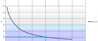
Current transformer with parameters Sn = 10 VA; Ztr = 0.3 Ohm; Kpk.nom = 10; Ifirst = 600 A; Isecond = 5 A.
A terminal of type 7SJ80 is connected to the current transformer, in which overcurrent protection and current cut-off are activated. The current cut-off response setting Israb.to = 3150 A. The connection diagram of the current transformers is a full star. The maximum value of the short-circuit current at the place where the protection is installed ISC.max = 12.45 kA. The relay protection terminal is installed in the relay compartment of the switchgear cabinet and is connected to current transformers with copper wires with a cross-section of 2.5 mm2.
Examples of spacing for transformers
Below is the calibration interval for various models of current transformers (indicated in years):
- TTI-A – 5;
- T-0.66 – 8;
- TOP-0.66 – 8;
- TShP-0.66 – 16;
- TOL-10 – 8;
- TPL-10 – 8.
Different manufacturers may specify different calibration intervals for similar equipment models.
It must be taken into account that transformers that have not passed the next verification are not allowed for operation. Therefore, the owner needs to monitor the timely organization and implementation of these works.