Bringing the secondary winding to the primary
Primary and secondary currents, voltages and other quantities are of the same order if the primary and secondary windings have the same number of turns. Let us therefore consider, instead of a real transformer, an equivalent so-called reduced transformer, the primary and secondary windings of which have the same number of turns.
Let's imagine that the real secondary winding of the transformer with the number of turns w2 is replaced by an imaginary, or reduced, winding with the number of turns w2' = w1. In this case, the number of turns of the secondary winding will change in
once. The quantity k is called reduction coefficient or transformation coefficient . More details about what is called the transformation ratio and how to determine the transformation ratio are described in the article “Principle of operation and types of transformers.”
As a result of such a replacement, or reduction, the electromotive force E2' and the voltage U2' of the reduced winding also change k times compared to the values of E2 and U2 of the real secondary winding:
| (1) | |
| (2) |
In order for the powers of the reduced and real windings to be equal in all operating modes, it is necessary to observe the equality
where I2' is the reduced secondary current. Hence, taking into account the second equality (2), it follows that
| (3) |
The magnetizing forces of the reduced and real windings based on expressions (1) and (3) are equal:
| (4) |
In order for electromagnetic processes in real and reduced transformers to proceed identically, the reduced and real secondary windings must create the same magnetic fields. To do this, in addition to meeting condition (4), it is necessary that the given secondary winding have the same geometric dimensions and configuration and be located in the window of the transformer magnetic core in the same way as the real secondary winding (see, for example, Figure 1, in the article “Magnetic cores of transformers "and Figure 1, in the article "Structural elements and methods of cooling oil transformers"). Therefore, the total cross-section of all turns of the reduced winding should be the same as that of the real winding, and the cross-section of each turn of the reduced winding should decrease by k times. But since the reduced winding has k times more turns, then, as a result, the active resistance of the reduced winding is k2 times greater than the real one:
Since with the same geometric dimensions and the same arrangement of the coils, their inductance and inductive resistance are proportional to the squares of the number of turns, then the same relationship exists between the inductive resistance of the reduced winding x2' and the real x2:
It is obvious that the losses in the reduced and real windings are the same:
The relative voltage drops in the secondary windings of the reduced and real transformers are also the same:
Thus, all energy and electromagnetic relationships in the reduced and real transformers are the same, which makes it possible to carry out the indicated reduction.
| (5) | |
| (6) |
Design and principle of operation
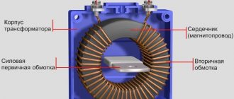
The design of the transformer includes the following components:
- core,
- primary and secondary windings.
Principle of operation of a transformer
Depending on the features of the design device, the operation of transformers is ensured by the presence of automatic units that control the unit, switching units for connecting power, oil tanks for cooling, etc.
When voltage is applied to the primary coil, a magnetic field is formed and an electromotive force (EMF) arises, inducing voltage on the secondary circuit. Transformation of voltage and current characteristics is achieved by different numbers of turns on the input and output circuits. For the above transformer, the number of turns at the input and output is conventionally assumed to be equal, which ensures the above-mentioned value of the transformation ratio, while maintaining the number of phases and other network characteristics unchanged.
Equivalent circuit parameters
Let's consider the parameters of equivalent circuits in Figure 1 with k = w1 / w2 [see equality (1)]. Reduced mutual inductance based on equalities (6) and (10), presented in the article “Inductance of transformer windings and electromagnetic scattering” and equality (19), this article
or based on expression (4), presented in the article “Inductance of transformer windings and electromagnetic dissipation”
| (20) |
The last term of expression (20) is very small compared to the first, and therefore with sufficient accuracy
| M12' ≈ Lс1. | (21) |
Accordingly, according to expression (3) presented in the article “Transformer Voltage Equations” and expressions (11), (19), (21) of this article,
x12' = k × x12 = ω × k × M = ω × M12' ≈ ω × Lс1
or
| x12' ≈ xс1 = ω × w12 / Rµc. | (22) |
Consequently, the resistance x12' is, with great accuracy, equal to the self-induction resistance of the primary winding from the flux closing along the magnetic circuit.
Branches 1 – 2 of equivalent circuits in Figure 1 are called magnetizing branches. The magnetizing current flowing through these branches
| creates the resulting magnetizing force of the transformer windings Fres = w1 × (I1 + I2') = w1 × I1 + w1 × I2' = F1 + F2, which in turn creates a resulting rod flow with amplitude Fs. The voltage on these branches in accordance with expression (22) of this article and expression (3) presented in the article “Principle of operation and types of transformers” that is, equal in value and inversely in sign to the electromotive force E1, which is induced in the primary winding by the resulting flux of the magnetic circuit, or the main flux of the transformer, and lags behind it by 90°. The leakage inductance of the primary winding, according to expressions (9) and (10), presented in the article “Inductance of transformer windings and electromagnetic leakage” and expression (17) of this article, S1 = L11 – k × M = Lc1 + Lв1 – k × Mc – k × Мв . But based on equations (4) and (6) presented in the article “Inductance of transformer windings and electromagnetic dissipation” That's why
Similarly, according to expressions (9) and (10) presented in the article “Inductance of transformer windings and electromagnetic scattering” and expression (18) of this article But based on equations (5) and (6), presented in the article “Inductance of transformer windings and electromagnetic scattering” and therefore
Thus, the leakage inductances S1, S2 and S2' and the leakage inductances at k = w1 / w2 are determined by magnetic fluxes that are closed mainly through the air. However, the second terms of equalities (23) and (24) cannot be neglected in comparison with the first ones, and therefore flows closed through the air can be called scattering flows only conditionally.
|
Equivalent circuit taking into account magnetic losses
Losses in the steel of the magnetic circuit pMG at a given frequency are proportional to the following quantities:
pmg ∼ Bc2 ∼ Фc2 ∼ E12.
Thus, the losses pmg are proportional to the square of the voltage U12 at terminals 1 – 2 of the magnetizing circuit of the equivalent circuit in Figure 1, a. If an active resistance rmg is connected to these terminals in parallel with x12' = xc1, as shown in Figure 2, a, then the losses in this resistance will also be proportional to U12. The resistance value rmg can be selected so that the losses in it are equal to the magnetic losses:
pmg = m1 × U122 / rmg = m1 × E12 / rmg.
From here
| rmg = m1 × E12 / pmg. | (26) |
Figure 2. Magnetizing circuit of an equivalent circuit taking into account magnetic losses
The value of pmg at a given electromotive force E1 can be considered known from calculated (see the article “Calculation of the magnetic circuit of a transformer”) or experimental data. Then rmg can also be considered known.
Magnetizing current
is divided in two branches of the magnetizing circuit (Figure 2, a) into active Ima and reactive Imr components (see the article “Calculation of the magnetic circuit of a transformer”), of which the first determines the power of magnetic losses, and the second creates the flux of the magnetic circuit.
The circuit with two parallel branches of the magnetizing circuit is in good agreement with real physical phenomena. However, it is more convenient to carry out calculations based on an equivalent circuit if you combine two parallel branches of circuit 2 into one common branch, as shown in Figure 2, b. Then the resistance of this branch
| (27) |
Since rmg >> x12', then
| (28) |
With increasing saturation of the magnetic circuit, that is, with increasing Fs, E1 or U1, the resistance x12' at f = const decreases. However, in this case rm ≈ const, and the value of rm decreases.
The equivalent circuit of the transformer taking into account magnetic losses according to Figure 2, b is shown in Figure 3, a. If we use the notation
| Z1 = r1 + jx1 ; Z2' = r2' + jx2' ; Zm = rm + jxm, | (29) |
| Figure 3. Equivalent circuit of a two-winding transformer taking into account magnetic losses |
then the equivalent circuit can be depicted more compactly, as shown in Figure 3, b. In no-load mode, I2' = 0 and I1 = Im – the no-load current of the transformer.
The result was a very simple T-shaped equivalent circuit of the transformer, which is a passive four-terminal network. The resistance of the magnetizing circuit of this circuit Zm reflects the phenomena in the ferromagnetic magnetic circuit. It is significantly greater than the resistances Z1 and Z2', which include active resistances and inductive leakage resistances of the windings. For power transformers in relative units
zm* = 25 – 200; z1* ≈ z2*' = 0.025 – 0.10.
Voltage equations and the equivalent circuit of a transformer can also be represented in relative units. Bearing in mind that
Un = zn × In ,
the left-hand sides of equations of the form (15) can be divided into Un, and the right-hand sides into Zн × In, as a result of which the transition to relative units will be made. The absolute values of U, I, r, x and Z in equivalent circuits can also be replaced by relative ones. In this case, calculations of the operating modes of the transformer can be carried out in relative units.
It is easy to see that the relative values of the resistances, currents and voltages of the secondary circuit will depend on what value of the coefficient k was used when bringing the secondary winding to the primary. The uncertainty in this matter disappears if k is always determined in the same way. For example, in power transformers they always take k = w1 / w2.
Basic transformer equations. Reduced transformer and equivalent circuit.
The equivalent circuit of a transformer is an equivalent electrical circuit that reflects the basic electromagnetic phenomena occurring in the transformer. The equivalent circuit is drawn up based on the transformer equations (2.15) and (2.18).
We will take into account losses in the magnetization circuit with the parameters
Then:
or
We assume that the no-load current Ī0 is equal in magnitude to the effective value of the no-load current, and the power
equal to the power of the transformer in idle mode. Taking this into account, it is possible to solve the system of basic transformer equations with respect to current Ī1:
Equation (2.20) corresponds to a four-port network - an equivalent electrical equivalent circuit shown in Fig. 2.11.
Rice. 2.11. Equivalent equivalent circuit
The equivalent circuit includes the parameters of the primary winding R1
and
X1
are the given parameters of the secondary winding
R΄2
and
X΄2
and the parameters of the magnetizing circuit
Rm
and
Xm
.
Voltage Ū1 is applied to the input of the four-port network, the reduced load value Z΄H
- Current Ī1 passes through the primary winding, current Ī2 passes through the secondary winding
,
current
Ī0
.
In accordance with Kirchhoff's law, the sum of currents converging at nodes a or b is equal to zero: . Using the equivalent circuit, current values, power, power losses, etc. can be determined.
It should, however, be remembered that the parameters of the equivalent circuit can be considered unchanged when the voltage on the primary winding changes within 10% of the nominal value. With a further increase in voltage, the steel of the magnetic circuit becomes saturated, and the value of Xm
and the magnetizing current increases.
The parameters of the equivalent circuit can be determined from the results of no-load and short-circuit experiments of the transformer.
The no-load experiment comes down to measuring the primary voltage, current and power of the primary winding with the secondary winding open (Fig. 2.12b).
Rice. 2.12. No-load experience (a) and equivalent circuit of a transformer in this mode (b)
Using a voltage regulator RN, the voltage U0
, equal to the nominal value.
The power P0
consumed by the primary winding and the no-load current
I0
.
The transformer no-load experience corresponds to an equivalent circuit (Fig. 2.12.6)
Since the no-load current Ī0
is small compared to the rated current of the transformer
Ī1
, then the electrical losses in the windings, which depend on the square of the current, are neglected and it is assumed that all the power consumed by the transformer in no-load mode is spent on compensating for magnetic losses in the steel:
. (2.21)
Based on the measured power P0 and current I0, we can use formula (2.21) to determine the active resistance of the magnetizing circuit Rm
:
. (2.22)
Further, since the scattering flux is many times less than the main flux, it is believed that X1 + Xm ≈ Xm
, therefore the total resistance of the magnetizing circuit is:
Zm = U10 /I0,
(2.23)
and its inductive reactance:
(2.24)
By measuring the voltage Ul0
and
U20
of the primary and secondary windings, the transformation ratio can be determined:
k = U10 /U20
(2.25)
The short circuit experience (Fig. 2.13,a) is that the secondary winding of the transformer is short-circuited through an ammeter (resistance ZH
=0), and such a reduced voltage is supplied to the primary by means of a voltage regulator RN so that the currents of the primary and secondary windings are equal to the rated values
I1n
and
I2n
. This voltage is called the short circuit voltage and is designated UK.
Short circuit voltage UK
In high-power power transformers it is usually 5...15% of the rated value, in low-power transformers - 25...50%.
| |
Rice. 2.13. Short circuit experience (a) and equivalent circuit (b)
A distinction must be made between a short circuit under operational conditions and a short circuit experience. The first is an emergency condition of the transformer: unacceptably large currents arise in the windings, a large amount of heat is released inside the transformer, which can cause its destruction.
The short circuit experience serves to determine the most important parameters of the transformer: internal voltage drop, losses in conductors, etc.
Electromotive force E2K
, induced in the secondary winding during a short circuit experience, must be equal to the voltage drop of the secondary winding, i.e.
E2K = I2Z2
since U2
=
0. Consequently, during a short circuit experiment, E2K
is
2 ...
Directly proportional to the EMF
E2K
, the flux in the core decreases, and with it the magnetizing current that excites it.
At the same time, during the short-circuit experience, the losses in the winding conductors are the same as under the rated load mode, and the losses in the core are negligible, since they are proportional (approximately) to the flux.
Therefore, we can assume that during a short circuit experience, all the power P1K is spent on electrical losses in the conductors of the transformer windings. Since the magnetizing current in this mode can be neglected, then Ī1 = Ī΄2.
Putting X = X1+X̄΄2 ≈ 0, and R = R1 + R2
, we obtain for power
Р1K
(2.26)
With an increase in the rated apparent power SH of the transformer, the active power PKH
, spent during a short circuit test at rated current, decreases relatively.
For example, at a rated apparent power SH = 5...20 kVA the ratio PKH / SH
= 3.7...3%, and at
SH
= 320...5600 kVA this ratio will be equal to
PKH / SH
= 2...1%. This means that the greater the power of the transformer, the lower the electrical losses in its windings and the higher its efficiency.
Based on (2.26), the active resistance of the simplified equivalent circuit of the transformer is determined:
, (2.27)
which is called the active short circuit resistance of the transformer. This value, determined directly from the results of a short circuit experiment, only approximately determines the value of the active resistance RK of the loaded transformer. To ensure the minimum dimensions of the transformer, the current density in the conductors and the induction in the cores are usually selected at a value that corresponds to the maximum permissible heating temperatures during operation. Heating significantly changes the active resistance of the conductors of the transformer windings and the losses in them. Therefore, to determine losses in windings under load, the RK value found from a short circuit experiment must be reduced to a temperature of 75 °C.
As shown above, the flux closing through the magnetic circuit depends on the voltage applied to the primary winding of the transformer, and magnetic losses in steel are proportional to the square of the induction or the square of the magnetic flux. Therefore, due to the smallness of UK, magnetic losses in steel and no-load current can be neglected. Therefore, we can assume that Rm ≈ 0 and Xm ≈ 0. Then the equivalent circuit takes the form shown in Fig. 2.13, b.
Equivalent circuit parameters:
ZK = Z1+ Z΄2=UK / I1H.
R1+ R΄2 = RK = P1K / I2H, (2.28)
The triangle formed by the vectors of voltage drops across the total, inductive and active short-circuit resistances is called the characteristic triangle or short-circuit triangle (Fig. 2.14).
Rice. 2.14. Characteristic triangle
Legs ĪKHK
and
ĪKRK
are called the reactive and active components of the short circuit voltage, respectively. When the load current of the transformer changes, they change in proportion to the change in current.
This allows you to build vector diagrams for a simplified equivalent circuit of a transformer and make quantitative calculations. The ratio of voltage UK =I1HZK
to the rated voltage of the transformer UH
,
expressed in%, is called
the relative short circuit
uK% = (I1HZK / UH)∙100%.
(2.29)
The relative short circuit voltage is an important parameter and is indicated in the transformer data sheet. According to the known value uK%
it is possible to determine the steady-state short-circuit current under real operating conditions, i.e. at rated voltage:
I1K = UH/ZK=100I1H / uK%.
(2.30)
For example, the steady-state short-circuit current of a transformer having andK%
= 5 is twenty times its rated value, which is unacceptable because it leads to destruction of the transformer. To protect transformers from short-circuit currents in real operating conditions, circuit breakers are used that are capable of disconnecting the circuit for a period. Let us note again: the greater the power of the transformer, the less its no-load current and losses in it, and the greater the short-circuit current.
Thus, the equivalent circuit of a transformer makes it possible to study it in various modes, and experiments with no-load and short circuit make it possible to determine its main parameters.
