Comparison of AC and DC
The direction of flow of electrical energy is determined by direct and alternating current.
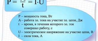
The difference is that in the first case, the charges move in one direction and continuously, while in the second, the direction of the flow changes at regular intervals. The latter is accompanied by alternating voltage levels and changing poles at the source from positive to negative and vice versa, which makes processes in loads more complex than in the case of constant voltage. The key advantage of DC is that it can be easily stored or created in portable chemical sources. But the use of AC makes it possible to transmit electrical energy over long distances much more economically. The fact is that the power W=I*V transmitted from the station is not fully delivered to the destination point. Part of it is spent on heating power lines in the amount of W= I2*R.
An obvious way to reduce losses is to reduce resistance by increasing the thickness of the wires. But there is an economic limit to its implementation: thick conductors are more expensive. In addition, massive wires require expensive supporting structures.
The problem has a brilliant solution if you change the voltage and current while maintaining the power. For example, with an increase in V by a thousand times and a corresponding decrease in I, the power value remains the same, but the losses decrease by a factor of millions, since they are quadratically dependent on the current strength. The problem remains of converting voltage to safe values when distributing it to consumers.
This is not possible with DC, but AC allows you to change the values of I and V while maintaining power using transformers. Energy companies use this property to transport electricity. The ability to transform determines the main, practically applicable difference between alternating current and direct current.
Three-phase and single-phase networks. Differences and advantages. Flaws
In the electrical equipment of residential apartment buildings, as well as in the private sector, three-phase and single-phase networks are used. Initially, the electrical network comes from a power plant with three phases, and most often a three-phase power network is connected to residential buildings. Further it has branches into separate phases. This method is used to create the most efficient transmission of electric current from a power plant to its destination, as well as to reduce losses during transportation.
To determine the number of phases in your apartment, just open the distribution board located on the landing, or right in the apartment, and see how many wires enter the apartment. If the network is single-phase, then there will be 2 wires - phase and zero. Another possible third wire is grounding.
If the electrical network is three-phase, then there will be 4 or 5 wires. Three of them are phases, the fourth is zero, and the fifth is grounding. Also, the number of phases is determined by the number of circuit breakers.
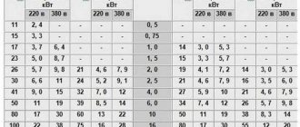
Three-phase networks in apartments are rarely used, in cases of connecting old electric stoves with three phases, or powerful loads in the form of a circular saw or heating devices. The number of phases can also be determined by the input voltage. In a 1-phase network the voltage is 220 volts, in a 3-phase network between phase and zero it is also 220 volts, between 2 phases it is 380 volts.
If you do not take into account the difference in the number of network wires and the connection diagram, then you can determine some other features that three-phase and single-phase networks have
- In the case of a three-phase power supply, phase imbalance is possible due to uneven distribution of load phases. A powerful heater or stove can be connected to one phase, and a TV and washing machine to the other. Then this negative effect occurs, accompanied by asymmetry of voltages and currents in phases, which leads to malfunctions of household devices. To prevent such factors, it is necessary to pre-distribute the load across phases before laying the electrical network wires.
- A 3-phase network requires more cables, conductors and switches, which means you won't be able to save too much money.
- The power capabilities of a single-phase household network are significantly less than those of a three-phase network. If you plan to use several powerful consumers and household devices, power tools, then it is preferable to supply a three-phase power supply to the house or apartment.
- The main advantage of a 3-phase network is the low voltage drop compared to a 1-phase network, provided the power is the same.
This can be explained by the fact that in a 3-phase network, the current in the phase conductor is three times less than in a 1-phase network, and there is no current at all on the conductor.
Advantages of a 1-phase network
The main advantage is the cost-effectiveness of its use. Such networks use three-wire cables, compared to five-wire cables in 3-phase networks. To protect equipment in 1-phase networks, you need to have single-pole circuit breakers, while in 3-phase networks you cannot do without three-pole circuit breakers.
In this regard, the dimensions of the protection devices will also differ significantly. Even on one electric machine there is already a saving of two modules. And in terms of dimensions this is about 36 mm, which will significantly affect when placing the machines in a panel on a DIN rail. And when installing a differential machine, the space savings will be more than 100 mm.
Three-phase and single-phase networks for a private home
Electricity consumption by the population is constantly increasing. In the middle of the last century, there were relatively few household appliances in private homes. Today the picture is completely different in this regard. Household energy consumers in private homes are multiplying by leaps and bounds. Therefore, in your own private property there is no longer a question of which power supply networks to choose for connection. Most often, in private buildings, power networks with three phases are installed, and a single-phase network is abandoned.
But is a three-phase network worth such superior installation? Many people believe that by connecting three phases, it will be possible to use a large number of devices. But this does not always work out. The maximum permissible power is determined in the technical conditions for connection. Typically, this parameter is 15 kW for the entire private household. In the case of a single-phase network, this parameter is approximately the same. Therefore, it is clear that there is no particular benefit in terms of power.
But, it must be remembered that if three-phase and single-phase networks have equal power, then for a 3-phase network you can use a cable of a smaller cross-section, since the power and current are distributed over all phases, therefore, there is less load on the individual phase conductors. The rated current of the circuit breaker for a 3-phase network will also be lower.
The size of the distribution board is of great importance, which for a 3-phase network will be noticeably larger. This depends on the size of the three-phase meter, which is larger than the single-phase one, and the input machine will also take up more space. Therefore, the distribution board for a three-phase network will consist of several tiers, which is a disadvantage of this network.
But three-phase power also has its advantages, which are expressed in the fact that three-phase current receivers can be connected. They can be electric motors, electric boilers and other powerful devices, which is an advantage of a three-phase network. The operating voltage of a 3-phase network is 380 V, which is higher than in a single-phase type, which means that more attention will have to be paid to electrical safety issues. The same applies to fire safety.
As a result, several disadvantages of using a three-phase network for a private home can be identified:
- You need to obtain technical conditions and permission to connect the network from the power supply.
- There is an increased risk of electric shock and also a risk of fire due to the increased voltage.
- Significant overall dimensions of the power input switchboard. For owners of country houses, this disadvantage is not of great importance, since they have enough space.
- It is necessary to install voltage limiters in the form of modules on the input panel. In a three-phase network this is especially true.
Advantages of three-phase power supply for private homes:
- It is possible to distribute the load evenly across phases to avoid phase imbalance.
- Powerful three-phase energy consumers can be connected to the network. This is the most tangible benefit.
- Reducing the nominal values of protection devices at the input, as well as reducing the cross-section of the input cable.
- In many cases, it is possible to obtain permission from the energy sales company to increase the permissible maximum level of power consumption of electricity.
As a result, we can conclude that practically introducing a three-phase power supply network is recommended for private buildings and houses with a living area of more than 100 m2.
Three-phase power is especially suitable for those owners who are going to install a circular saw, a heating boiler, or various drive mechanisms with three-phase electric motors.
Other owners of private houses do not need to switch to three-phase power supply, as this can only create additional problems.
Receiving mechanism
It is known that there are two types of alternating current:
- single-phase;
- three-phase.
Single-phase and three-phase AC voltage
It is worth considering the differences in the methods of obtaining these types of current.
Single-phase
In a 1-phase generator, all the coils of the induced winding are connected to one line. Consumers are powered by a 2-wire wire (phase and neutral). The voltage in the 1-phase network is 220 V.
Three-phase
The induced winding of a 3-phase generator consists of 3 parts, located at an equal distance from each other and each connected to its own line. That is, the angle between them is 1200. As a result, in each line the current is shifted in phase relative to the adjacent one by the same angle.
Such a load is called symmetrical and to connect it a neutral wire is not needed at all: the currents of each phase cancel each other out at common points. But often the load is asymmetrical: in addition to 3-phase consumers, 1-phase consumers are powered by separate phases.
Then the currents in the phases are unequal and mutual cancellation will not happen - at least 1 neutral wire is needed.
The main advantages of 3-phase power supply:
- simplifies the transfer of high power.
- it becomes possible to create a rotating magnetic field in electric motors.
Industrial power plants only have 3-phase generators.
If the neutral wire breaks, 1-phase consumers connected to different phases are supplied with a voltage of 380 V, which leads to their breakdown. Therefore, in Western countries, each phase is equipped with a neutral wire. In our country, because of savings, we still use one common one.
Advantages and disadvantages
Like everything material, three-phase current has its pros and cons. The positive aspects of using systems with three or four wires include:
- efficiency. To transmit electricity over long distances, cores made of non-ferrous metals with low resistivity are used. The voltage is divided proportionally to the number of cables. By distributing loads, engineers can reduce the number of wires and their cross-section, which, given the cost of rare materials, provides noticeable savings;
- efficiency. The power parameters of three-phase transformers are an order of magnitude higher than single-phase transformers with smaller magnetic core sizes;
3-phase current transformer
- simplicity. When consumers are simultaneously connected to a three-phase system, an additional electromagnetic field is generated. The phase shift effect has made it possible to create simple and reliable brushless electric motors, the rotor of which is made according to the principle of a conventional blank and is mounted on ball bearings. Asynchronous electric drives with a squirrel-cage rotor are widely used as power units. The main advantage of such motors is the ability to change the direction of rotation of the axis by switching to different phase wires;
- variability. In circuits with several phases, it is possible to obtain different voltages. The user will be able to change the power of the heater or servo drive by switching from one cable to another;
- reducing the stroboscopic effect. It is achieved by independently connecting different lamps to individual phases.
You might be interested in this: Coil inductance, its purpose, characteristics, formulas
Along with its advantages, three-phase current has its disadvantages. They include:
- connection difficulty. To connect a three-phase network to a private or industrial building, you must obtain special permission and technical specifications from the local energy sales company. This event is quite expensive and troublesome. Even if all conditions are met, a positive result is not always guaranteed;
- application of enhanced security systems. The three-phase network supplies a voltage of 380 V, so additional devices for protection against electric shock and short circuits are required, which can lead to fire. In such cases, another three-pole circuit breaker with higher ratings is installed at the input. It will help avoid fire in the event of a short circuit;
- the need to install auxiliary modules to limit overvoltage in the distribution board. It is necessary in case the neutral cable breaks, which will lead to an increase in voltage in one of the phases.
The transition to three-phase current is advisable for owners of premises whose area is more than 100 square meters. meters. This applies to private homes and industrial buildings. This connection scheme will allow you to redistribute the load evenly across all consumers and avoid power surges.
AC networks
Four-wire power line 220/380 V, such power lines are common in single-story residential areas, in rural areas. The two lower wires are a wired radio broadcasting network.
Voltage conversion in electrical networks
Wiring diagram for a three-phase network in multi-apartment residential buildings.
Electricity producers (hydroelectric power plants, thermal power plants, combined heat and power plants, nuclear and other power plants) generate alternating current of industrial frequency (in Russia - 50 Hz), with a voltage of about 10 - 20 kV.
Then the electric current flows to transformer substations, which are located next to power plants, where the electrical voltage increases.
High voltage alternating current is transmitted to consumers via power transmission lines (PTL). Increasing the voltage is necessary in order to reduce losses in power line wires (see Joule-Lenz law, as the electrical voltage increases, the current in the electrical circuit decreases, and heat losses decrease accordingly)
.
At the other end of the power line there is a step-down transformer substation, where high-voltage alternating current is reduced by transformers to the value required by the consumer.
In the vast majority of cases, three-phase current is transmitted along power lines, however, there are direct current power lines, for example, the Volgograd-Donbass high-voltage direct current line
,
high-voltage direct current line Ekibastuz-Center
,
mainland South Korea - Jeju Island
and others.
The use of direct current allows you to increase the transmitted electrical power, transfer electricity between power systems using alternating current of different frequencies, for example, 50 and 60 hertz, and also not synchronize neighboring power systems, as was done on the border of the Leningrad region with Finland (see box DC Vyborg - Finland)
.
In Russia, general purpose electrical networks use three-phase current with a phase-to-phase voltage of 380 Volts.
The quality of electrical energy - its electrical voltage and frequency must be strictly observed.
(three phase wires and one neutral (neutral) wire) are supplied to residential buildings (rural streets).
power lines (overhead or cable power lines) with a phase-to-phase voltage of 380 volts (since 2003, 400 volts according to GOST 29322-2014).
A phase wire and a neutral wire are supplied to a separate apartment (or rural house), the electrical voltage between the “phase” and “zero” is 220 volts (since 2003, 230 volts according to GOST 29322-2014). You can determine which wire is which using a phase indicator. For example, phase “A” is supplied to the first apartment, phase “B” is supplied to the second apartment, phase “C” is supplied to the third apartment, and so on...
How does three-phase voltage differ from single-phase
Three phase = line voltage 380 Volts, Single phase = phase voltage 220 Volts
The article is addressed to novice electricians. I, too, was once a beginner, and I am always happy to share knowledge and raise the professional level of my readers.
So, why do some electrical panels receive a voltage of 380 V, and some - 220? Why do some consumers have three-phase voltage, while others have single-phase? There was a time when I asked myself these questions and looked for answers to them. Now I’ll tell you in a popular way, without the formulas and diagrams that textbooks abound.
Very briefly, for those who will not read further: the voltage of 380 V is called linear and operates in a three-phase network between any of the three phases. The 220 V voltage is called phase and operates between any of the three phases and neutral (zero).
In other words. If one phase approaches the consumer, then the consumer is called single-phase, and its supply voltage will be 220 V (phase). If they talk about three-phase voltage, then we are always talking about a voltage of 380 V (linear). Who cares? More details below.
How are three phases different from one?
In both types of power there is a working neutral conductor (ZERO). I talked in detail about protective grounding here; it is a broad topic. In relation to zero in all three phases - the voltage is 220 Volts. But in relation to these three phases to each other, they have 380 Volts.
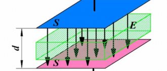
Voltages in a three-phase system
This happens because the voltages (with active load, and current) on the three phase wires differ by a third of the cycle, i.e. at 120°.
You can read more in the electrical engineering textbook - about voltage and current in a three-phase network, and also see vector diagrams.
It turns out that if we have three-phase voltage, then we have three phase voltages of 220 V each. And single-phase consumers (and there are almost 100% of them in our homes) can be connected to any phase and zero. You just need to do this in such a way that the consumption in each phase is approximately the same, otherwise phase imbalance is possible.
Read more about phase imbalance and what causes it - here.
And it is best to protect yourself from phase imbalance using a voltage relay, for example Barrier or FiF EuroAutomatika.
Disadvantages of AC
- The most important disadvantage of alternating current is the presence of reactive power. As is known, a capacitor and an inductor exhibit their reactive properties only in alternating current circuits. Simply put, the coil and capacitor create reactance to AC current, but do not consume it. As a result of this, of the total power supplied by the alternator, part of the power is not spent on performing useful work, but only circulates uselessly between the generator and the load. This power is called reactive power and is harmful. Therefore, they try to minimize it.
However, most loads - motors, transformers and the wires themselves - are inductive elements. And the greater the inductance, the greater the proportion of reactive power from the total and this must be dealt with.
- The second main disadvantage of alternating current is that it does not flow across the entire cross-section of the conductor, but is displaced closer to its surface. As a result, the area through which electric current flows decreases, which in turn leads to an increase in the resistance of the conductor and an increase in power losses in it.
The higher the frequency, the more current is displaced to the surface of the conductor and, ultimately, the higher the power loss.
Why are there usually three phases and not four?
Almost all novice electricians ask this question. In fact, the number of phases is unlimited. There can be 1, 2, 3, 4 and even 10. However, three-phase systems are widely used. This is due to the fact that such a circuit is sufficient to solve most problems.
You might be interested in Socket with a timer: instructions for use and principle of operation
Such systems are mostly used for power plants in production. The rotor rotation is 360 degrees, and the phase shift is 120 degrees. It is quite enough to spin the armature to the required speed and get the required power from the engine. Increasing the number of phases will only increase the cost of the installation itself, since it will require installing additional coils and connecting extra cables.
Important! Adding phases to the existing three does not increase the efficiency of the unit or increase its power. From a rational point of view, this only adds to the cost of installations while maintaining the same operating parameters.
Electrification of railways using alternating current
The Russian AC passenger electric locomotive EP1P is produced at the Novocherkassk Electric Locomotive Plant.
In Russia and the republics of the former USSR, about half of all railways are electrified using single-phase alternating current with a frequency of 50 Hz. Voltage ~ 25 kV (usually up to 27.5 kV, taking into account losses)
is fed to the contact wire, the second (return) wire is the rails.
Electrification is also carried out according to the 2 × 25 kV (two twenty-five kilovolts each)
, when a voltage of ~ 50 kV is applied to a separate supply wire
(usually up to 55 kV, taking into account losses)
, and half the voltage of 50 kV is applied to the contact wire from autotransformers
(i.e. 25 kV)
.
Electric locomotives and AC electric trains do not require alteration when operating on 2 × 25 kV sections.
A policy is being pursued to further expand the AC traction range both through newly electrified sections and through the transfer of some lines from direct current to alternating current. Transferred to 1990s - 2000s:
- on the East Siberian Railway: section Slyudyanka - Irkutsk - Zima; - on the Oktyabrskaya Railway: section Loukhi - Murmansk; — on the Volga Railway: Saratov and Volgograd railway junctions; - on the North Caucasus Railway: sections Mineralnye Vody - Kislovodsk and Beshtau - Zheleznovodsk.
It should be noted that dual-system electric locomotives are also produced that can operate on both alternating and direct current (see VL61D, VL82 and VL82M, EP10, EP20).
Generation and transformation
The principle of generating electricity is simple. If a magnetic field rotates along a stationary set of coils of turns of a conductor or, conversely, a coil rotates around a stationary magnetic field, then due to the phenomenon of electromagnetic induction, a potential difference arises at the ends of the windings. With each change in the angle of rotation resulting from the described circular motion, the output voltage will also change in both magnitude and direction.
The described conditional generator at a constant angular speed of rotation of the shaft produces a sinusoidal AC with a waveform that is no different from that supplied in a household network. Real generators are much more complex, but operate on the same principles of electromagnetic induction.
These same laws help not only in the production of AC, but also in its transmission and distribution. Voltage conversion by power companies cannot be accomplished without electrical machines called transformers.
This is why Tesla's invention was so important to the revolution in electricity transportation.
Any transformer consists of the following elements:
- primary and secondary windings;
- core.
The word “primary” is used for the winding to which the electrical voltage that needs transformation is applied. The induced voltage on the secondary coil is always equal to that applied on the primary, multiplied by the ratio of turns of the secondary to the primary. The transformer allows you to change the voltage step by step.
Advantages and disadvantages of single-phase manicure products
Advantages
single-phase cosmetic preparations are undeniable:
- Instead of a base, gel polish and finishing product, you only need to buy a single-phase gel. This makes it possible to significantly save on the cost of a manicure.
- A thinner consistency, which makes it easier to distribute the product evenly over the nail plate. In contrast to three-phase systems, which, having a thicker and more viscous texture, require more painstaking application, as well as careful leveling.
- More suitable for use by inexperienced people than three-phase systems.
- Despite the fact that the use of a single-phase drug involves layer-by-layer application, the total thickness of all layers is less than when using three-phase systems. This helps to reduce the load on the nail plates, and they better tolerate gel polish coating.
- Single-phase products do not contain aggressive components, so they are ideal for use by people with sensitive skin.
- When using preparations of this type, the nail plates breathe, since the coating is not airtight.
Despite all the advantages of the innovative single-phase gel, it also has disadvantages:
- Due to the fact that during the manicure process a separate glossy layer is not applied, which performs protective functions, the wearing period of single-phase gel on nails is shorter than in the case of three-phase products.
- The advantage of the product is its liquid consistency, but at the same time it is a disadvantage that creates difficulties for novice masters and ordinary users. The single-phase preparation spreads heavily over the surface of the nail plate and is difficult to control. Therefore, the polymer often gets onto the cuticle and under the side ridges. A separate problem is the formation of the apex point or the so-called “stress point” - the highest point of the artificial nail, which bears the greatest load.
- Also, the use of a single-phase nail product limits the artist’s imagination and does not provide the opportunity to perform some designs. For example, it will not be possible to realize the idea of a manicure if it involves the use of three-dimensional figures and stickers.
Types of electric generators
Alternating current generators are divided into two types:
- synchronous. The frequency of the induced EMF corresponds to the rotor speed;
- asynchronous. There is a difference between the rotational speeds and the induced emf, called slip. They are designed simpler than synchronous ones and are resistant to overloads and short circuits, which is why they are used in transport. They are not suitable for powering frequency-sensitive consumers.
According to the method of powering the winding of the inductor (electromagnet), electric generators are divided into 4 types:
- powered from a third-party source;
- devices with self-excitation, a part of the electric current generated by the generator is supplied to the winding, converted by the rectifier into direct current. Such a generator only needs a third-party source during startup. The battery is used for this purpose;
- devices with an additional low-power generator installed on the same shaft as the main one. This additional generator powers the inductor winding. Only it needs a third-party source for starting; accordingly, the requirements for a low-power battery are reduced;
- permanent magnet generators. There is no winding, no power required. The design flaws are mentioned above.
The principle of obtaining alternating current
The conversion of mechanical energy into electrical energy occurs due to electromagnetic induction. This phenomenon is as follows: if the magnetic flux (MF) crossing the conductor is changed, an electromotive force (EMF) will subsequently arise. A change in the magnetic field can be achieved by moving the conductor in a magnetic field.
Electromotive force of the current source
The emf is equal to E = B * L * V * sin α, where:
- B—MF induction, Gn;
- L—conductor length, m;
- V is the speed of movement of the core relative to the field, m/s;
- α is the angle between the conductor velocity vector and the field lines.
The direction of the EMF is determined by the rule of the right hand: if you position it so that the field lines enter the palm, and the thumb bent at a right angle indicates the direction of movement of the conductor, 4 connected fingers will indicate the direction of the EMF.
Receiving alternating current
Current generation is based on the phenomenon of electromagnetic induction, which was discovered by Michael Faraday. Its essence is this: in a conductor located in a magnetic field with changing characteristics, an electromotive force (EMF) arises.
The magnetic field parameters mean:
- field line density;
- the angle of their direction relative to the conductor.
There are several ways to ensure changes in magnetic field parameters:
- move (rotate) the conductor in the field of a permanent magnet;
- rotate a permanent magnet around a conductor;
- place a current-carrying element in the field of an electromagnet (a wire wound in the form of a coil) with alternating current flowing through it.
The first two methods are used in electric generators, the last one is used in current transformers. Moving a magnet or conductor requires mechanical energy. It is converted by the generator into electric power. The direction of the EMF is determined by the right hand rule.
In this position, when the field lines enter the palm, and the thumb moved to the side coincides with the vector of movement of the conductor, the other fingers point to the direction of the EMF. The simplest alternating current generator is a wire frame rotating between permanent magnets and connected to an electrical circuit.
The contact between the moving frame and the stationary conductive elements of the chain is sliding: rings are attached to the ends of the frame, and graphite brushes (have a low coefficient of friction) pressed against these rings are attached to the ends of the chain.
The rotating part of a generator or electric motor, in our example this is a frame, is called a rotor. Fixed - stator.
The EMF induced in the frame is determined by the formula: E = B*S*ω*sinα, where B is the magnetic induction, S is the area of the frame, ω is the angular frequency, A is the angle of rotation of the frame.
Only the angle α changes, therefore, the graph of the EMF changes has the form of a sinusoid. Since the current, in accordance with Ohm's law, is equal to the ratio of the emf to the load resistance (I = E/R), it is also sinusoidal.
The sinusoidality of the EMF and current variables means that they periodically change not only the magnitude, but also the direction to the opposite.
Schematic diagrams of alternating current generators
Three phase current
> Theory > Three-phase current
Most alternators, as well as power transmission lines, use three-phase systems. Current transmission is carried out along three lines (or four) instead of two. Three-phase current is an alternating electric current system where the values of currents and voltages change according to a sinusoidal law. The frequency of sinusoidal current oscillations in Russia and Europe is 50 Hz.
Three-phase circuit diagrams
In a star circuit configuration, there are three phase wires. If the zero points of the power supply system and the receiver are connected, then a four-wire “star” is obtained.
The circuit distinguishes between the phase-to-phase voltage located between the phase conductors (it is also called linear), and the phase voltage – between the individual phase conductors and the N-conductor.
What phase voltage is is most clearly determined by constructing vectors - these are three symmetrical vectors U(A), U(B) and U(C). Here you can see what line voltage is:
- U(AB) = U(A) – U(B);
- U(BC) = U(B) – U(C);
- U(CA) = U(C) – U(A).
Important! Vector constructions give an idea of the shift between the consistent phase and interphase voltages - 30°.
Therefore, the line voltage for a star circuit with uniform loads can be calculated as follows:
Uab = 2 x Ua x cos 30° = 2 x Ua x √3/2 = √3 x Ua.
Other indicators of phase voltage are found similarly.
Linear and phase voltage, if we sum up the vector quantities of all phases, are equal to zero:
- U(A) + U(B) + U(C) = 0;
- U(AB) + U(BC) + U(CA) = 0.
If an electrical receiver with a resistance identical in each phase is connected to the star:
Za = Zb = Zc,
then you can calculate the linear and phase currents:
- Ia = Ua/Za;
- Ib = Ub/Zb;
- Ic = Uc/Zc.
Construction of vectors in the “Y” diagram
As applied to general cases of a “star” system, linear current quantities are identical to phase ones.
It is usually assumed that the source feeding the electrical receivers is symmetrical, and only the impedance determines the operation of the circuit.
Since the summing current indicator corresponds to zero (Kirchhoff's law), in the case of a four-wire system, no current flows in the neutral conductor. The system will behave the same whether there is a neutral conductor or not.
For the active power of a three-phase receiver, the formula is valid:
P = √3 x Uф I x cos φ.
Reactive power:
Q = √3 x Uф I x sin φ.
"Y" for asymmetrical load
This is a circuit configuration where the current magnitude of one phase is different from another, or the phase shifts of currents are different compared to voltages. Interphase voltages will remain symmetrical. Using vector constructions, the appearance of a shift of the zero point from the center of the triangle is determined. The result is asymmetry of phase voltage values and the appearance of Uo:
Uo = 1/3 (U(A) + U(B) + U(C)).
Despite the asymmetric load, the summing current indicator is zero.
"Y" without N-conductor with asymmetric load
Important! The operation of the circuit with an asymmetric load depends on whether or not there is an N-conductor.
The circuit behaves differently when an N-conductor with insignificant impedance Zo = 0 is connected. The zero points of the power supply and the power receiver are galvanically connected and have the same potential. The phase voltage of different phases acquires an identical value, and the current value in the N -conductor:
Io = I(A) + I(B) + I(C).
Four-wire "Y" circuit
When transmitting power, it is common to use three-wire systems at high and medium voltage levels. At low voltage levels, where unbalanced loads are difficult to avoid, four-wire systems are used.
"Δ" scheme
By connecting the end of each phase of the power receiver to the beginning of the next, you can obtain a three-phase current with phases connected in series. The resulting circuit configuration is called a "triangle". In this form, it can only operate as a three-wire one.
With the help of vector constructions, understandable even for dummies, phase and linear voltages and currents are illustrated. Each phase of the electrical receiver is connected to a linear voltage between two conductors. Line and phase voltages are identical at the power receiver.
Scheme “Δ” and construction of vectors
Interphase currents for the “triangle” are I(A), I(B), I(C). Phase – I(AB), IBC), I(CA).
Linear currents are found from vector constructions:
- I(A) = I(AB) – I(CA);
- I(B) = I(BC) – I(AB);
- I(C) = I(CA) – I(BC).
The summing current quantity in a symmetrical system corresponds to zero. RMS values of phase currents:
I(AB) = I(BC) = I(CA) = U/Z.
Since the phase shift between U and I is 30°, the line current in this configuration will be equal to:
I(A) = I(AB) – I(CA) = 2 x I(AB) x cos 30° = 2 x Iph x √3/2 = √3 x Iph.
Important! The effective value of the line current is √3 times the effective value of the phase current.
Methods
Thus, to obtain alternating current, it is enough to rotate a wire frame with an electrical circuit connected to its ends in the field of a permanent magnet. The source of energy is the force that rotates the frame and overcomes the resistance of the magnetic field.
Every half turn, the conductors of the frame change the direction of movement relative to the poles of the magnet; accordingly, the direction of the EMF in the frame also changes.
Receiving alternating current
The angle between the velocity vector and the field lines varies according to the law α = w*t, where:
- W—angular velocity of frame rotation, rad/s;
- T is the time elapsed from the initial moment when the velocity vector was parallel to the lines of force, s.
That is, the EMF depends on sin (wt): E = f (sin (wt)). Consequently, the graph of changes in the EMF value over time has the form of a sinusoid. The alternating current caused by this EMF is called, accordingly, sinusoidal.
The simplest generator described can be improved:
- The permanent magnet is replaced with an electric one by placing several coils in the stator (excitation winding). As a result, a uniform magnetic field is obtained and thus an ideal sinusoidality of the EMF is achieved (the quality of operation of the devices increases). The excitation winding is powered by a low-power DC generator or battery;
- instead of one frame, several are placed on the rotor: the EMF increases several times. That is, the rotor is also a winding.
The problematic part of such a generator is the moving contact between the rotating rotor and the electrical circuit.
It consists of a copper ring and graphite brushes, pressed against the ring by springs. The higher the power of the generator, the less reliable this unit is: it sparks and wears out quickly. Therefore, in powerful industrial generators installed at power plants, the stator and rotor windings are swapped: the excitation winding is placed on the rotor, and the inducing winding is placed on the stator.
The moving contact remains, but due to the low power of the excitation winding, the requirements for it are reduced. Industrial AC frequency is 50 Hz. That is, the voltage periodically changes direction and magnitude 50 times per second or 3000 times per minute. If there are 2 poles in the excitation winding, to achieve this frequency, the rotor must rotate at a speed of 3000 rpm.
This is what happens in generators of thermal and nuclear power plants. But in hydroelectric power plants, it is physically impossible to rotate the rotor at such a speed: the propellant is falling water, and its speed is much less than the speed of superheated steam with a pressure of 500 atm.
In addition, the rotor of the hydraulic station is enormous in size even at a rotation speed of 3000 rpm.
Its outer sections would move at the speed of a supersonic fighter, which would lead to the destruction of the structure. To reduce the number of revolutions, increase the number of pole pairs in the electromagnet. The rotation frequency will be W = 3000 / n, where n is the number of pole pairs. That is, if there are 10 pairs of poles, to generate alternating current with a frequency of 50 Hz, the rotor must be rotated at a speed of only 300 rpm, and with 20 pairs - 150 rpm.
In electrical engineering, another method of producing alternating current is practiced - by converting direct current. An electronic device is used - an inverter, consisting of power transistors, a microcircuit that controls them and other elements. At the output of the inverter, you can obtain an alternating voltage of any magnitude and frequency. The simplest circuits produce rectangular alternating voltage, while more complex and expensive ones produce stabilized sinusoidal voltage.
Examples of inverter applications:
- switching power supplies and inverter welding machines. The mains current with a frequency of 50 Hz is rectified and then fed to an inverter, which produces an alternating current with a frequency of 60-80 kHz. Purpose: at such a high frequency, the dimensions of the transformer and losses in it are sharply reduced, that is, the device as a whole becomes more compact and economical;
- autonomous diesel and gasoline generators to power equipment sensitive to voltage quality. A diesel generator in its pure form produces low-quality current, since its shaft rotation speed changes when the load is converted. The inverter eliminates all these fluctuations and produces a stable, high-quality voltage at the output;
- DC power lines.
For a number of reasons, it is more profitable to transmit particularly significant powers over very long distances using direct current rather than alternating current. At the final point, it is converted by an inverter into AC power frequency and sent to the local power grid.
What is the difference between three-phase current and single-phase current?
The main difference between a single-phase circuit and a three-phase one:
- single-phase current is supplied to consumers through one conductor, three-phase - through three;
- to complete the network, a neutral cable is required, therefore in circuits with one phase there are two of them, and in three - four;
- power increases with increasing number of phases;
- simplicity of network design;
- voltage drops appear in a single-phase circuit with an increase in the number of electricity consumers;
- When one wire is disconnected in a three-phase system, the current continues to flow in the remaining two wires. In single-phase, the voltage disappears completely.
Note! The three-phase system allows the use of different voltage ratings when powering equipment with different power parameters
Why do we need three-phase current?
Single-phase and three-phase alternating current are widely used in industrial and domestic applications. However, recently more and more consumers are choosing to abandon the former and are leaning toward the latter.
You may be interested in this Designation of the neutral protective conductor
And it's not even a matter of increasing power and including more electrical equipment. Sometimes the difference between the power load is not even noticeable, and under certain network parameters, the input power for both circuits may be the same.
The main consumer is three-phase equipment. This group includes:
- asynchronous electric drives;
- heating installations;
- industrial equipment.
The most common consumer of three-phase current is an asynchronous motor. It is as part of this network that they show the best operating parameters, high efficiency at relatively low energy costs.
Asynchronous motor
In addition, drives, heaters, boilers, electric furnaces, and heaters do not distort phases. For sensitive equipment, such subsidence is a very sensitive topic.
Note! In reality, it is impossible to provide the same load on all three phases. Accordingly, the voltage will always be different.
Since there are several more consumers in the room, an additional system is needed that can distribute the load evenly across all receivers. This requires a three-cable chain. The load is connected to the three-phase current network to the circuit that has the fewest consumers.
Three-phase current connection diagram
However, distribution systems for three-phase current circuits are very bulky and take up a lot of space. It requires additional security systems, since the voltage of such networks is 380 V. In the event of a short circuit, the current will be many times greater than with the usual 220 V.
Edison and Tesla
Hippolyte Pixie managed to create the first alternating current generator in 1835. It was a permanent magnet device that worked by rotating a handle. Entrepreneurs of that time were interested in DC generation and did not quite understand where the invention could be applied and why it was necessary to obtain AC.
The real competition for electrical transmission standards began in the late 1880s. years, when the struggle began between the major energy companies for dominance in the market for their own patented energy systems. It was a rivalry between the electrification concepts of two great inventors: Nikola Tesla and Thomas Edison.
Edison invented and improved many devices necessary for the first direct current generation and transmission systems. Within a short time, his company was able to open more than 200 stations in North America. The enterprise grew, and the inventor hired Nikola Tesla, a young engineer from Europe, to carry out work on improving the equipment. The new employee brought to Edison's attention revolutionary work for that time, based on variable value technologies. Tesla's ideas were rejected and the inventors went their separate ways.
George Westinghouse, on the contrary, reacted to the discoveries of the Serbian engineer with great interest and bought all Tesla's patents. After the Westinghouse enterprise, it experienced many upheavals, including those associated with Edison’s powerful propaganda companies. The finale of the struggle came when Tesla's system was chosen to cover an exhibition in Chicago. This event introduced the world to the benefits of multiphase AC generation and transmission. Since then, most electrical devices and networks have been ordered to meet the new standard. The main dates of the War of Currents were:
- 1870 - Edison created the first DC generator;
- 1878 - Edison Electric Light Co. founded in New York;
- 1882 - Edison opened the Pearl Street generating station with 5 thousand lights;
- 1883 - Tesla invented the transformer;
- 1884 - Tesla invented the AC generator;
- 1888 - Tesla demonstrates a multiphase electrical system, Westinghouse buys his patents;
- 1888 - execution by electric chair, invented by Edison as a means of propaganda campaign demonstrating the dangers of Tesla's technology.
- 1893 - Westinghouse Electric Company triumphs at the Chicago Fair.
Step-by-step technology for gel nail extensions
Step by step gel nail extension
as follows. Stage
the first, preparatory, consists of disinfecting hands, removing
cuticles in any usual or convenient way. Nail surface
degreased for strong adhesion and then sanded to avoid
peeling. The edge of the nail is filed and given the desired shape. Each layer of gel
must be dried under a special ultraviolet lamp. And this,
in addition to its main purpose, it helps to avoid fungal infections in the future
diseases. There are three-phase and two-phase nail extension systems
gel. Gel extensions are carried out using a two-phase and three-phase system. Each of them consists of a certain number of components, which has its own purpose. For example, in a three-phase system, the first layer is responsible for adhesion of the nail plate to the artificial material. The second layer models the nail, and the third provides strength, creating a smooth, shiny surface. In a two-phase system, one component is used for modeling and adhesion, and the second for strength. There is also a single-phase system in which the gel performs all of the above functions.
Beautiful manicure, well-groomed nails
The step-by-step technology of gel nail extension involves applying two or three layers of gel, each of which is dried in turn under an ultraviolet lamp. Sometimes when drying under a lamp, a burning sensation occurs. Then the procedure is suspended and they wait until all symptoms disappear. The extension process ends with nail design. The entire gel extension process takes up to three to four hours and lasts up to two weeks.
From my experience, I know that a real professional master takes an hour and a half, and if there are complex patterns on the nails, it takes two hours. Correction, which is carried out after ten to fourteen
days after extensions, allows you to “forget” about manicure for a couple of months. Do you want the coating to last long? On the day of extensions, you should not do housework: washing dishes, hand washing, replanting flowers. Because all these things will have to wait until “tomorrow”, when the nails become “reinforced concrete”.
Gel extensions, like all cosmetic procedures, also have unpleasant consequences.
- Firstly, expansion is a rather labor-intensive and lengthy process that requires considerable costs, including financial ones.
- Secondly, nails under the gel do not “breathe” at all, which will subsequently require long-term treatment and recovery with the intake of vitamins and special procedures.
Step-by-step technology for gel nail extensions often causes unpleasant sensations, which depend on the threshold of sensitivity and professionalism of the artist. Despite the smooth and dense coating, gel nails are more fragile than acrylic nails. To avoid injury to the nail, you can cover it with a biosculpting gel, which half consists of natural resins, natural vitamins and proteins. The presence of such materials allows the nail to “breathe”, and after restoration, such nails look healthier and stronger.
154
Structure
An electrical circuit is a set of devices and elements aimed at delivering current to the consumer and converting it into another type of energy: heat, light or mechanical work.
There are three parts in the circuit:
- power supply;
- transmitting part: wires, switches, transformers, stabilizers, etc. Everything that is used to transmit, transform electrical energy and maintain its quality at the proper level;
- consumers: lamps, electric motors, heaters, etc.
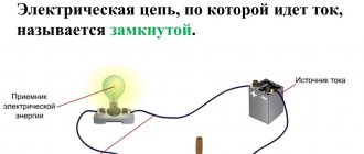
The power source - generator, battery, solar panel - is called the internal part of the circuit, the remaining components are called external. The source is also called an active element, others - passive. The electrical circuit functions only in a closed form, that is, in a continuous form. When opened, the current in it drops to zero, although the section on the generator or battery side remains energized.
Based on the number of pins, circuit components are divided into two types:
- bipolar: have one pair of terminals. Example - diode, resistor;
- multi-terminal: have more than two terminals. Example - transformer (4 pins).
Processes in an electrical circuit are described by Ohm's and Kirchhoff's laws.
The components in it are connected in three ways:
- sequentially;
- parallel;
- in a combined way.
The following terms are used:
- branch. A section of series-connected elements in a parallel or combined circuit. The laws of electrical engineering state: the current strength within a branch is the same, regardless of the resistance value of its constituent components, and the total resistance of a branch is equal to the sum of the resistances of all its components. In a circuit with only a series connection of components, no branches are distinguished; it is called an unbranched circuit;
- node The place where the chain branches. It is generally accepted that the sum of currents converging at a node is equal to the sum of currents emanating from it. The voltage drop for parallel branches between the branching and convergence points is the same;
- circuit. A set of branches that represents a closed path for current.
According to functionality, individual parts in the structure of the electrical circuit are divided into the following types:
- power Includes elements that generate, conduct, convert and consume electricity;
- auxiliary. Various additional devices not related to the power section. For example, reactive power compensation installations, fuses;
- measuring The devices related to this part allow you to monitor the parameters of the network and devices connected to it;
- manager Equipment for adjusting device parameters or turning them on/off.;
- signaling. Reports changes in network parameters by turning on alarm devices.
According to complexity, electrical circuits are divided into:
- simplest: source connected to consumer;
- simple: contain one circuit;
- complex: have several circuits.
In complex chains there are:
- multi-circuit;
- multi-node;
- planar;
- volumetric.