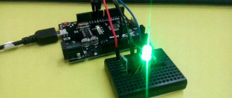
The name Arduino is currently a sort of “fashionable” word for most radio amateurs and everyone who is more or less familiar with electronics, since this platform allows you to create electronic devices quickly and cheaply. The presence of an extensive online community of this platform makes it an ideal choice for those who have just begun their acquaintance with electronics and programming. Even people who do not have a technical education (and this is exactly who it was originally created for) will find it quite easy to master Arduino.
Why is this platform so relevant? How to get started with it? How can it improve your lifestyle? All these issues will be discussed in this article. To do this, we will learn how to install the Arduino IDE on your computer and load it with a small program that will blink an LED, which we will connect to the Arduino using a breadboard.
What is Arduino
Unfortunately, some novice radio amateurs consider Arduino a microcontroller, but this is not entirely true. Let's try to figure out what it is.
Arduino is an open source development platform that consists of an easy-to-use hardware and programming environment. The most common type of hardware is Arduino UNO, and the programming environment is called Arduino IDE. In addition to Arduino UNO, there are quite a lot of similar boards - Arduino Mega, nano, mini, but in this article, for training purposes, we will use Arduino UNO. And the Arduino IDE is exactly the software environment with which we will program the Arduino UNO board.
Getting started with Arduino
In everyday language, Arduino is an electronic board into which you can plug in many different devices and make them work together using a program written in the Arduino language in a special programming environment.
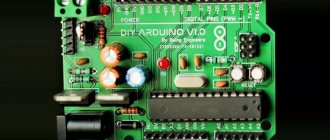
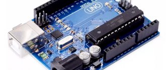
Most often the board looks like this:
The figure shows one of the Arduino boards - Arduino Uno. We will study it in more detail in the following lessons.
You can plug wires into the board and connect many different elements. Most often, a breadboard for solderless mounting is used for connection. You can add LEDs, sensors, buttons, motors, communication modules, relays and create hundreds of interesting smart device designs. The Arduino board is a smart socket that will turn everything connected on and off depending on how it was programmed.
All work on the project is divided into the following stages:
- We come up with an idea and design it.
- We assemble an electrical circuit. Here we need a breadboard, which simplifies the installation of elements. Of course, you will need skills in working with electronic devices and the ability to use a multimeter.
- We connect the Arduino board to the computer via USB.
- We write a program and write it to the board by literally pressing one button on the screen in a special Arduino programming environment.
- Disconnect from the computer. Now the device will work autonomously - when the power is turned on, it will be controlled by the program that we wrote into it.
The program and programming environment look like this:
The screen shows a program (in Arduino slang the text of the program is called “sketch”), which will blink with a light connected to input 13 on the Arduino UNO board. As you can see, the program is quite simple and consists of instructions that are understandable for those who know English. The Arduino programming language uses its own dialect of the C++ language, but all C++ features are supported.
There is another option for writing code - a visual editor. There is no need to write anything here - you can simply move the blocks and put together the desired algorithm from them. The program will be loaded into the connected board with one click of the mouse button!
The visual environment is recommended for use by elementary school students; more senior engineers are better off immediately learning the “real” Arduino - it’s quite simple, and besides, knowledge of C++ will not harm anyone.
Overall, everything looks pretty clear, doesn't it? It remains to figure out the details.
Installing Arduino IDE
Before you start working with Arduino, you need to install the Arduino IDE programming environment on your computer/laptop. All steps described below for installing this software environment will be focused on the Windows operating system; for other operating systems the sequence of actions will be approximately the same. If you have problems with other systems, help can be found at the following links - for Mac users and Linux users. Before you start installing the Arduino IDE, make sure that you have administrator rights on your computer - this will make the installation easier.
Step 1 . Download Arduino IDE from the official website - https://www.arduino.cc/download_handler.php.
Step 2 . Run the downloaded exe file.
Step 3 . In the window that opens, click on “I Agree” to agree to the terms of the Arduino license.
Step 4 . In the installation options window, check all the boxes (see figure).
Step 5 . In this step, you need to select where to install the Arduino IDE. The default installation path is Program files on drive C - it is highly recommended to leave this path.
Step 6 . In this step, you can watch the Arduino IDE being installed on your computer (see picture). Once the installation is complete, click the “completed” button.
Step 7 . After the installation is complete, run the Arduino.exe file. An IDE window will open with a minimum of code inside it - see the picture.
EQUIPMENT TECHNOLOGY DEVELOPMENT
As a professional microcontroller programmer, I do not consider Arduino controllers a good element for developing complex systems. But I fully appreciated the ease of developing projects in this system, the ease of learning, writing programs, and the ease of using ready-made hardware modules.
List of lessons Next lesson
Introduction.
There are a large number of lessons on programming in the Arduino system on the Internet. Most of them come down to primitive programs that perform sequential actions from other people's functions.
It is immediately noticeable that the programs are written extremely unprofessionally.
- Signals from hardware devices connected to the controller are not processed well enough. For example, the simplest elements are buttons. There is some rattling of the buttons, they may be connected with long wires that are susceptible to interference. In a reliable system, it is necessary to use digital filtering of signals from buttons or dry contact sensors. As a rule, in the example lessons the state of the button signals is simply read.
- Reliable microcontroller programs require cyclic resetting of variables and data integrity monitoring.
- A good microcontroller programming style involves structured programming. These are not formal words. As you know, you can write beautiful, structured programs in assembler, or you can create something like this in C++.
- Probably the most important thing is multitasking. Almost all lessons contain sequential actions of the program. We looked at the state of the button, then lit the LED, called up some incomprehensible function... The result is achieved simply, but the result is somehow flawed.
If we take, for example, my controller program for a refrigerator based on a Peltier element. How to make it according to this principle? How can you perform all the necessary actions using simple sequential operations? This program is written in PIC controller assembler. It performs many parallel operations:
- With a period of 10 ms, it interrogates three buttons, provides digital filtering of button signals, and eliminates debouncing.
- Regenerates data from seven-segment LEDs and LEDs every 2 ms.
- Generates control signals and reads data from two DS18B20 temperature sensors with a 1-wire interface. It is necessary to generate a new read or write bit for each sensor every 100 µs.
- Every 100 µs reads the analog values of the output current, output voltage, and supply voltage.
- Averages the output current and voltage values over 10 ms, calculates the power on the Peltier element.
- A complex system of regulators is constantly working: stabilization of current, voltage, power on a Peltier element;
- PID (proportional integral differential) temperature controller.
All these operations must be performed cyclically with different cycle periods. And nothing can be skipped or paused. Such a program cannot be implemented by a simple sequence of actions.
So, in my Arduino programming lessons I am going to pay attention to the above problems, I am going to teach practical programming . Programming Arduino controllers that work with real objects.
At the same time, I focus the lessons on non-professional programmers , on people who want to learn how to program controllers.
Despite the scary expressions - digital filtering, multitasking, it is much simpler than it seems. You just need to strictly handle all possible situations and not turn a blind eye to them.
Rather, these will be lessons in programming and electronics , because... using microcontrollers without additional hardware does not make sense. They have to manage something.
In each lesson I will strive to create a complete module that can be used in future projects. The ideal option is to create something like an operating system that uses the drivers (functions) of all external hardware. I managed to create such a system using PIC controllers to control complex packaging equipment. It includes an environment for performing parallel tasks and drivers for working with stepper motors, sensors, buttons, display, etc. I hope it will work on Arduino.
General information about Arduino.
Arduino is the name of hardware and software for creating simple electronic automation and robotics systems. The system has a completely open architecture and is aimed at non-professional users.
The Arduino software part consists of an integrated software environment (IDE), which allows you to write, compile programs, and also load them into the hardware.
The hardware consists of electronic boards with a microcontroller, accompanying elements (power stabilizer, quartz resonator, blocking capacitors, etc.), a port for communication with a personal computer, connectors for I/O signals, etc.
Due to the simplicity of device development, the Arduino system has become extremely widespread. In Yandex alone there are up to 150 thousand requests for “Arduino” per month. Despite the ease of developing projects, quite complex systems can be created using Arduino, especially after the emergence of high-performance controller options.
Arduino boards use Atmel AVR microcontrollers with a bootloader embedded in them. Using a bootloader, a program is written to the microcontroller from a personal computer without the use of hardware programmers.
To program Arduino, the C/C++ language is used, with some features.
There are a huge number of clones of Arduino hardware. Most of them are complete analogues of branded Arduinos, often not inferior in quality.
List of lessons Next lesson
Support the project
5
Author of the publication
offline for 3 days
Edward
214
Comments: 1748Publications: 178Registration: 13-12-2015
Connecting your Arduino board to your computer
Once you have installed the Arduino IDE on your computer, the next logical step is to connect the Arduino UNO board to your computer. To do this, simply use the programming cable (blue) and connect it to the Arduino board and the USB port of your computer.
The blue programming cable can perform the following three functions:
- It powers the Arduino UNO board, that is, to ensure the execution of programs on it, you simply need to power it using a USB cable.
- The ATmega328 microcontroller located on the Arduino UNO board is programmed through it. That is, the program code is sent from the computer to the microcontroller via this cable.
- It can function as a serial communication cable, meaning it can be used to transfer data from the Arduino UNO to a computer - useful for program debugging purposes.
After you supply power to the Arduino UNO board, a small LED on it will light up - this indicates that power is supplied to the board. You may also notice another LED blinking - this is the result of the LED blinking control program that is loaded into your board by default by its manufacturer.
Since you are connecting the Arduino board to the computer for the first time, it will take some time for the drivers to install successfully. To check whether everything was installed correctly and detected, open the “Device manager” on your computer.
In Device Manager, open the “Ports” option “Ports (COM & LPT)”, click on it and see if your board is displayed correctly there.
It is worth noting that you should not pay attention to what port number is displayed on your Arduino board - it may, for example, look like CCH450 or something similar. This port number is simply determined by the board manufacturer and does not affect anything else.
If you cannot find the “Ports (COM & LPT)” option in Device Manager, this means that your board was not detected correctly by the computer. In most cases, this means a problem with the drivers - for some reason they were not automatically installed for your board. In this case, you will have to manually install the necessary drivers.
In some cases, the specified Device Manager option may show two COM ports for your board and you will not know which one is correct. In this situation, disconnect and reconnect the Arduino board to the computer - which of the COM ports will appear and disappear, which means that is the correct port.
You should remember that the COM port number will change every time you connect your board to the computer - don’t be alarmed, there’s nothing wrong with that.
Arduino.ru
This document explains how to connect your Arduino board to your computer and upload your first sketch.
- Required hardware - Arduino and USB cable
- The program is a development environment for Arduino
- Connect the board
- Install drivers
- Start the Arduino Development Environment
- Open the finished example
- Select your board
- Select your serial port
- Upload the sketch to Arduino
Required hardware - Arduino and USB cable
This tutorial assumes you are using an Arduino Uno, Arduino Duemilanove, Nano or Diecimila.
You will also need a USB cable (with USB-A and USB-B connectors): such as, for example, to connect a USB printer. (For Arduino Nano you will need an A to mini-B cable instead).
The program is a development environment for Arduino
Find the latest version on the download page.
After the download is complete, unzip the downloaded file. Make sure your folder structure is intact. Open the folder by double clicking on it. It should contain several files and subdirectories.
Connect the board
Arduino Uno, Mega, Duemilanove and Arduino Nano are powered automatically from any USB connection to your computer or other power source. If using an Arduino Diecimila, make sure the board is configured to receive power via a USB connection. The power source is selected using a small plastic jumper placed on two of the three pins between the USB and power connectors. Make sure it is installed on the two pins closest to the USB connector.
Connect the Arduino board to your computer using a USB cable. The green power LED labeled PWR should light up.
Install drivers
Installing drivers for Arduino Uno on Windows7, Vista or XP:
- Connect your board and wait for Windows to begin the driver installation process. After some time, despite all her attempts, the process will end in vain.
- Click on the START button and open Control Panel.
- In Control Panel, go to the System and Security tab. Then select System. When the System window opens, select Device Manager.
- Pay attention to the ports (COM and LPT). You will see an open port called "Arduino UNO (COMxx)".
- Right-click on the name “Arduino UNO (COMxx)” and select the “Update Driver Software” option.
- Click “Browse my computer for Driver software”.
- To finish, locate and select the Uno driver file, “ArduinoUNO.inf,” located in the Drivers folder of the Arduino software (not in the “FTDI USB Drivers” subdirectory).
- At this point, Windows will finish installing the driver.
See also: step-by-step screenshots for installing Uno under Windows XP.
Installing drivers for Arduino Duemilanove, Nano or Diecimila on Windows7, Vista or XP:
When you connect the board to your computer, Windows will begin the driver installation process (if you have not connected the Arduino board to your computer before).
In Windows Vista, the driver will be downloaded and installed automatically (it really works!)
In Windows XP, the Add New Hardware wizard will open.
- To the question “Connect to Windows Update to search for software? (Can Windows connect to search for software?)” select the answer “No, not this time.” Click Next.
- Select “Install from a list or specified location (Advanced)” and click “Next”.
- Make sure that “Search for the best driver in these locations” is selected; uncheck “Search removable media”; Select “Include this location in the search” and point to the drivers/FTDI USB Drivers folder in your Arduino distribution. (The latest driver can be found on the FTDI website). Click Next.
- The wizard will start searching and then tell you that “USB Serial Converter” has been found. Click "Finish".
- The Found New Hardware Wizard will reappear. Follow all the same steps with the same options and the same search path. This time "USB Serial Port" will be detected.
You can verify that the drivers are actually installed by opening the Windows Device Manager (located in the Hardware tab of the System Properties panel). Find “USB Serial Port” in the “Ports” section - this is the Arduino board.
Start the Arduino Development Environment
Double click on the Arduino application.
Open the finished example
Open the instant example sketch "LED" at: File > Examples > 1.Basics > Blink.
Select your board
You need to select the Tools > Board menu item that corresponds to your Arduino board.
Selecting Arduino Uno
For Duemilanove Arduino boards with ATmega328 (check the chip label on the board) select Arduino Duemilanove or Nano with ATmega328. In the beginning, Arduino boards were released with ATmega168; For these, choose Arduino Diecimila, Duemilanove, or Nano with ATmega168. You can read more about the board menu items on the “Development Environment” page.
Select your serial port
Select the Arduino Serial Device from the Tools | Serial Port. This will probably be COM3 or higher (COM1 and COM2 are usually reserved for hardware COM ports). To find the correct port, you can disconnect the Arduino board and reopen the menu; The item that disappeared will be the Arduino board port. Reconnect the board and select the serial port.
Upload the sketch to Arduino
Now just click the “Upload” button in the program - the development environment. Wait a few seconds - you will see the RX and TX LEDs on the board blinking. If the upload is successful, the message “Done uploading” will appear in the status bar. (Note: If you have an Arduino Mini, NG or other board, you need to physically issue the reset command with the button immediately before pressing the “Upload” button).
A few seconds after the boot is complete, you will see the pin 13 (L) LED on the board start blinking orange. Congratulations if so! You have received a ready-to-use Arduino!
Loading LED Flashing Program
Now let's load our first program into the Arduino board using the Arduino IDE, which we just recently installed. The installed Arduino IDE contains several example programs that will be very useful for beginners. Let's open one of these example programs using the following path File -> Examples -> Basics -> Blink (as shown in the picture).
This will open the Blink program - its purpose is to make the built-in LED on the Arduino board blink. After opening the program, we need to select the correct Arduino board - to do this, select the menu item Tool -> Boards -> Arduino UNO/Genuino as shown in the figure below.
Next we must select the correct port for our board. Earlier we saw that our board had a COM13 port defined. In your case it may be a different port. But for our case under consideration, we must select the menu item Tools -> Port -> COM13.
If everything is done correctly, you should notice that the port number (in our case COM 13) will appear at the bottom of the screen. After this, you need to click the download button (highlighted in blue) to the Arduino board as shown in the figure below.
After clicking this button, you will see the message “Compiling sketch” and then if the program upload is successful, you will see the message “Done Uploading” as shown in the image below.
If at this stage you encounter any errors that are not discussed in this article, then you can try to find them in the article about the 10 most common errors when working with Arduino.
Now let's try to write a program that will light up an LED when a button is pressed.
Let's summarize the lesson
In this short initial article, we learned what Arduino is, why this technology is called exactly what it is, and what typical projects using Arduino controllers look like. It's very easy to start creating interesting technical projects - you don't have to be an electronics engineer to do it. Just take an Arduino board, assemble the desired electronic circuit using it (you can find many ready-made examples on the Internet), connect the controller to your computer and download the program. The smart device is ready!
In the following lessons, we will learn how the controller works, disassemble the Arduino Uno board, and launch our first project.
Connection diagram
Shown in the following figure.
We will connect the button to the second pin of the Arduino, that is, one end of the button will be connected to the second pin of the Arduino, and the other to the ground. That is, whenever we press a button, ground will be supplied to the second pin of the Arduino.
The LED is connected to pin 3 through a 1 kOhm resistor. That is, the cathode of the LED is connected to ground, and the anode is connected to pin 3 of the Arduino through a resistor.
