When a person begins to be interested in electronics and radio engineering for the first time, his eyes run wide from the huge amount of practical and theoretical knowledge. A beginner is confronted with hundreds of diagrams that he does not understand, as well as many incomprehensible theoretical formulas.
In order to correctly and efficiently learn to understand electronic circuits and electronics in general, you need to consistently immerse yourself in theory, studying general terms and basic formulas, and then apply this data in the simplest practical experiments. For such immersion, special books have been developed that consistently introduce the general course of the subject, gradually going deeper.
This material will review the book “Electronics for Dummies”, some theoretical points and other books for study.
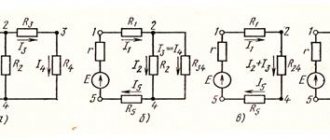
Diagram describing the flow of current
Basics of electronics for dummies
The book “Electronics for Dummies” contains hundreds of microcircuits and photographs that allow even the most uninitiated person to understand the principles of electronics. Detailed tips and instructions for conducting experiments will help you understand how certain electronic parts function. The material also contains recommendations for choosing the most important tools for working in this area and their full descriptions.
Important! As each chapter progresses, the reader is gradually immersed in a subject that fascinates him more and more. Theoretical knowledge is consolidated by practice by assembling simple but interesting devices.
The book contains the following sections:
- “Fundamentals of the theory of electrical circuits,” which defines voltage, current, conductors, and power dissipation.
- “Electrical Circuit Components,” which describes how simple elements such as resistors, transistors, diodes and capacitors control current and determine its characteristics.
- "Electrical circuits for universal purposes." Here we will tell you how to use the simplest digital and analog circuits in complex devices.
- “Electrical Circuit Analysis”, which will introduce you to the basic laws of electronics and teach you how to control the current and voltage in an electrical network, will teach you how to apply these laws in practice.
- “Safety precautions and recommendations for it.” This section will teach you how to safely work with electrical circuits and current in general, and will help you protect yourself and your devices from electric shock.
You might be interested in Electric current formulas
Cover of the book “Electronics for Dummies”
A multimeter will help you
You may remember what an ammeter and a voltmeter are from eighth grade (or whatever electricity and magnetism class you took in school). A multimeter, or, according to its passport, a “universal measuring device,” does everything that these guys do, and something else. The device allows you to measure voltage, circuit performance, current, temperature and transistor gain.
The specifications vary depending on the model, but all such devices are multifunctional. The most famous brand is DT, cheap and cheerful. If you want something more advanced right away, then Mastech or HoldPeak are usually recommended.
DT-800 series multimeter
A multimeter is needed primarily to check how theory matches practice. Heating of the elements and stray currents can affect the final result, so we need a monitoring device. And of course, if necessary (and for the sake of scientific interest), individual parts can be checked for functionality.
Even a fancy multimeter is easy to use. We select the mode, apply the probes to the desired places and take readings. The mode depends on what characteristic we are measuring and within what limits. The characteristics on multimeters are highlighted in separate frames with a signature, within these frames we select the second parameter - measurement limits.
WE RECOMMEND: Radio signal interception and analysis
I admit, I don't have a multimeter, and for some projects I had to borrow one from friends. I advise you to buy it for one simple reason: it will be much easier. You don’t have to rack your brains once again about why something doesn’t work—you can just check it.
Design and calculation of circuits: where to learn
In this article we will not delve into the design of circuits: there is a huge amount of material here, but it is well covered by the school (and for some, institute) curriculum and literature.
If you overslept everything, but understand English well, then you can start with lectures at Khan Academy - they are free, very intelligible and gradually move on from the very basics to more serious topics. There is even a short course that explains the structure of household appliances: electronic watches, coffee makers, hair dryers, and so on.
If you want something in Russian, then your path lies in a bookstore, technical library or their analogues on the Internet. Here are three books I recommend checking out first.
“The Art of Circuit Design”, P. Horowitz and W. Hill
The first chapter, “Fundamentals of Electronics,” is practically a high school physics course. Everything is presented in accessible language, the book will give you everything you need to get used to it from scratch, or will help fill in the gaps and systematize knowledge for those who are already familiar with circuitry. On the forums they write that the book is old and “fine points” are missed. But for some reason they don’t say what exactly is missing.
“Fundamentals of circuit design”, E. Vorobyova, V. Ivanchenko
The book is a lecture summary. Plus - brevity of presentation. The obvious downside is that this book may be a little complicated for a beginner.
"Digital Circuit Design and Computer Architecture", D. Harris and S. Harris
An excellent book that anyone who has ever been interested in computer architecture has heard of. Here we understand the hardware description languages - SystemVerilog and VHDL.
If you don’t have time to read, then circuit modeling software will help you understand what’s what (or serve as a visual illustration of what you’ve read). Among the most advanced, you can look at LTspice, DipTrace and open source Qucs. But there are a lot of options, there are even free simulators that run directly in the browser.
Example of a circuit routed in DipTrace
Starting the study of radio engineering for beginners
Before studying radio engineering or electronics, you need to understand why a person needs it. If this is a hobby for a couple of days or months, then it is better to quit the idea right away, because if you treat electronics carelessly and do not follow safety precautions, you can cause severe harm to your body. If you have been fascinated by this field since childhood, but did not have time to start studying, then now is the time to start. Gradual immersion implies:
- Obtaining or consolidating theoretical knowledge of physics. To begin with, it will be enough to have school knowledge of electrophysics, including a detailed study of Ohm's law - the basis of all electrics.
- Introduction to the theory. We should move from the more abstract things of physics to the more tangible. Theory implies an accurate and complete description of all concepts, parts, tools and devices that will be used in practice. It’s impossible to sit down and start soldering something without a theoretical foundation.
- Application in practice. The logical conclusion of the theory, which allows you to consolidate all the studied material and apply it when creating specific circuits or devices.
Ohm's law
Voltage and current - concepts
Any electronic component requires electrical current to operate. It is created by electric potential, that is, the “pressure” of particles. The potential itself is not enough for current to flow. You also need a conductor capable of passing it through yourself. If there is no conductor, then the potential goes into the air, which very well prevents the spread of current. Objects that stop current are called dielectrics, and those that allow current to flow through them are called conductors.
In addition to the conductor, current flow requires a potential difference that occurs in the circuit. An analogy can be drawn with a water pipe. If the same pressure is supplied from both sides, then no matter how strong it is, the water will not flow. The potential difference is called voltage. It is designated by the letter “U” and is measured in volts. The current strength is designated “I” and is measured in amperes.
You might be interested in this: Features of reactance
Important! By general agreement, it is believed that current flows from plus to minus, but in fact this is a convention. The thing is that negative electrons were discovered after this agreement. In diagrams and in practice, no one remembers where the current comes from and where it flows.
Visual definition of voltage
Digitrode
Do you want to learn electronics so you can create your own electronic devices and gadgets? There is a whole heap of educational literature available these days, but where to start? And what do you really need? If you don't know what you need to learn, then you can easily waste a lot of time learning unnecessary things. And if you skip a few simple but important first steps, you will spend a long time understanding elementary circuits without understanding how they work.
If your goal is to be able to implement your own ideas in electronic devices, then the following 10 steps are for you.
By following these tips, your study of electronics will go faster, even if you have never dealt with this field of science and technology. Some of these steps may take you several days, while others require only a few hours or even less than one hour if you find the right study material. Educational material on various topics can be found, for example, at https://uchitelya.com. It is advisable to skim through all the material first and then decide which sources you will use to solve each step.
Step one.
Explore the closed loop concept. If you don't know what it takes to make a circuit work, how can you create circuits at all? Closed loop is an important basis for many circuits, so you need to know how it works.
Step two.
Gain a basic understanding of voltage, current, and resistance. Roughly speaking, current flows, resistance resists, voltage pushes. And all these parameters influence each other. By understanding the essence and physical meaning of these quantities, you will be able to better understand the circuits.
Step three.
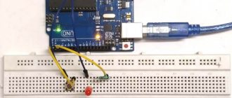
Learn electronics by building circuit diagrams. There is no need to wait, you should learn how to draw and assemble diagrams as early as possible. If you want to learn to swim, you must practice swimming. Same with electronics. You can take some kind of electronic circuit simulator, for example, Proteus, draw circuits in it and check their functionality. Better yet, assemble circuits on breadboards.
Step four.
Better understand the working principle of the following components: resistor, diode, LED, capacitor, transistor. These are the basic components of many circuits. In addition to educational literature on them, it is also advisable to read and study the documentation for specific element models.
Step five.
Gain experience using a transistor as a switch. The transistor is the most important component in electronics. In the previous step you received information about how it works. Now we need to test it in action. Create several different circuits where the transistor acts as a switch. Once you understand how it works in practice, you will know how to use transistors to control devices such as motors or lights.
Step six.
Learn to solder. Prototypes assembled on a breadboard are easy and quick to create and master. But their appearance leaves much to be desired, and the contacts can easily fall off. If you want to create an electronic device that looks good and works for a long time, then you should learn how to solder. This is a very interesting and useful activity.
Step seven.
Learn how diodes and capacitors behave in a circuit. In the previous steps, you understood the operating principles of basic electronics and learned how to assemble circuits. But your knowledge of electronics shouldn't stop there. Now we need to practically test the behavior of complex circuits, which will necessarily include capacitors and diodes.
Step eight.
Assemble circuits involving integrated circuits. So far, you've used individual components to build interesting and simple circuits. But you were still limited to basic functionality. But you can add more intelligence, memory, sound and other capabilities to your circuits. You just need to learn about integrated circuits. They may look very complex and difficult to understand, but in reality they are not. Once you learn how to use them, you'll open up a whole new world of possibilities in electronics.
Step nine.
Design your own circuit. Before this, you learned how to assemble training diagrams and understand them. Now you need to come up with something of your own. You can use programs to create circuits, for example, Proteus or Fritzing. Once you get comfortable with them, you can try something more complex, such as Eagle or KiCad. It is advisable not only to come up with a circuit diagram, but also to make a printed circuit board in order to gain the skill of creating electronic devices.
Step ten.
Learn to use microcontrollers in your projects. With integrated circuits and PCB manufacturing skills, you can already do a lot. But still, if you really want complete freedom to create whatever you want in terms of electronic devices, then you need to study microcontrollers. This will truly take your projects to the next level. After all, a few lines of code can replace entire chains of classical circuits. Once you've completed this step, you can already be considered knowledgeable in electronics. But don’t relax, there is still a lot to learn in this area, but it is interesting and exciting.
Voltage and current sources
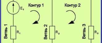
Sources often refer to elements that supply a circuit with electromagnetic energy. This energy is consumed by passive elements, stored by storage elements and spent in active resistance. An example of a source of such energy is a generator of constant, sinusoidal or pulse signals of various shapes. To analyze electronic circuits, it is convenient to introduce idealized current and voltage sources that take into account the basic properties of real sources.
A voltage source is a circuit element with two poles. A voltage is formed between these poles, which is set by certain functions of time and does not depend on the current in the circuit. This source in ideal condition is capable of delivering unlimited power. Real sources have internal resistance, so the resistance is connected to them in series.
An ideal current source is a circuit element through whose poles a current flows with a given pattern of changes over time. It does not depend on the voltage between its terminals. This independence means that the internal conductivity of the source is zero and the internal resistance is infinite.
Real current source
Radio electronics for dummies
About the authors Introduction Part I. The beginnings of electronics Chapter 1. From electrons to electronics What is electricity? What is an electron? The movement of electrons through conductors. Voltage is the driving force. An important unifying theory: electrons, conductors, and voltage. Where does electricity come from? Batteries: when others are tired, they are still full of energy Greenhouse conditions - electrical outlets Solar panels Where are electrical components used? Controlling Electricity Total Control of Electricity (IC) Sensor Detection Power When Electricity Becomes Electronics Building a Simple Circuit What to Do Next Getting to Know the Tools Along the Way Design Tools Measuring Tools The Wonderful World of Quantities Units of Measurement in Electronics Moving to Larger or Smaller Quantities Prefixes + units = ? Understood not about Ohm's law Conclusions from Ohm's law Calculations using large and small quantities Power and Ohm's law
Chapter 2. Safety of people and devices The sixth sense in electronics The danger of electric shock Electricity = voltage + current Direct or alternating current How to avoid getting electrocuted First aid Static electricity and its consequences Once again about the man on the hundred dollar bill How static can transform a radio element in a pinch of ash Tips for preventing static electricity buildup Grounding work tools Working with alternating current When it's hot: soldering safely Wearing protective clothing
Part II. Row 5, Tool Rack: Stocking Up for Future Use Chapter 3: The Ham Radio Workstation Hand Tools You Can't Live Without Screwdriver (a tool, not a cocktail!) Snapping off ends: Wire cutters and wire strippers Handling duck-billed pliers Magnifying glasses: “And this - to see you better...” Place for tools. There's a place for everyone Filling the workshop Where to store tools Tools that you don't need every day (but can come in handy) Working on a drill press Trimming parts with a bench saw or circular saw Doing delicate work with a burr Keeping tools clean and lubricated Shiny electronics Oil and lubricant for maintaining parts Tools for further cleaning and construction Glue for centuries Setting up a radio amateur laboratory The main ingredients of the ideal laboratory Choosing the ideal place for electronics training Triple threat: cold, heat and humidity Workbench
Chapter 4. First acquaintance: the most common electronic radio components Let resistors live Resistors and the values of their resistances Red, blue, cyan - choose any one The concept of resistor tolerance If it suddenly gets hot Twisting the potentiometer Capacitors: reservoirs of electricity A quick look inside the capacitor Farads: large and small Control operating voltage Dielectric here, dielectric there What is the capacitance of my capacitor? When a microfarad is not quite a microfarad The effects of heat and cold Positive feedback on the polarity of capacitors Changes in capacitance Diodomania Important parameters of diodes: maximum currents and voltages Where are the pluses of diodes? Fun with LEDs Resistors paired with LEDs Transistor: the eighth wonder of the world Studying the terminology of transistors About transistor packages Inserting a transistor into a circuit Types of transistors High packaging density in integrated circuits Linear, digital or combinational circuit? IC numbers What is pinout IC? Independent research of IC
Chapter 5. Consumer basket of a radio amateur Electrical connections Wires Connectors and connectors Turn on the power Turn on the power from the batteries Power from solar panels Turn on and off the electricity Vcf. and Off using switches Clicking relays Logic decisions. Logic Gates Using Logic in Electronics Basic Logic Gates Frequency Control of Quartz Resonators and Inductive Loops Energy Storage in Inductors Quartz Frequency Detection Who Sees the Light? Motion detectors Warm, warmer, hotter: temperature sensors DC motor vibrations Shouldn't we make a little noise? Loudspeaker speaking Sound generators
Part 111. Electronics on paper Chapter 6. Reading diagrams What is a circuit diagram and why is it needed Introduction to circuit design symbols The simplest circuit symbols Conventional graphic symbols of electronic radio elements Symbols of logical elements Other symbols Maintaining polarity One element for all occasions: radio components with variable rating Photosensitive components: see the light even at the end of the tunnel Alternative symbols
Chapter 7. Basic Functioning of Electronic Circuits What does an electronic circuit consist of? The simplest circuits Powering an incandescent lamp Changing the amount of current using a resistor Parallel (series) connection of elements Series connection Parallel connection Studying a voltage divider circuit Measuring current by measuring voltage Resistors and capacitors: one command How the dynamic duo of a capacitor and a resistor works Turning circuits on and off using RC -circuits Let's talk about transistors Transistor as a switch Transistor as an amplifier What else can transistors do? Operational Amplifier Simplifying Devices with Integrated Circuits
Part IV. Let's roll up our sleeves Chapter 8. Everything you need to know about soldering To solder or not to solder: that is the question Things absolutely necessary for soldering Choosing the right soldering iron Choosing a tip Preparing your soldering equipment Successful soldering Avoid cold soldering like the plague Soldering and static electricity Unsolder and re-soldering Spring suction in operation Suction with a bulb Useful tips and tricks
Chapter 9. How to make friends with a multimeter Basics of measuring with a multimeter Remember: safety comes first What to choose: a digital or analog multimeter? Multimeter in the Palm of Your Hand Multimeter Basics Multimeter Inputs and Their Functions Accuracy, Resolution, and Sensitivity Multimeter and Accessories Maximum Limit Auto-Ranging Additional Useful Features Multimeter Setup Five Basic Measurements You Can Take with a Multimeter Voltage Measurement Current Measurement Conductivity Measurement Switch Testing Testing fuses Testing resistors, capacitors and other electronic components Ha! It looks like everything here has burned down! Resistor testing Potentiometer testing Diode testing Capacitor testing Transistor testing
Chapter 10. Logic probe and oscilloscope With a logic probe into the electronics jungle Sound, light, curtain! Signals Too Fast (Even for Lightning Man) Know Your Circuit Getting Started with a Logic Probe Please Follow Standard Safety Precautions Connecting a Probe to a Circuit When the Indicators Are Silent Let's Take a Closer Look at the Oscilloscope What Does an Oscilloscope Do? Basic functions of an oscilloscope What to choose: desktop, handheld or computer? Oscilloscope Bandwidth and Resolution The Ins and Outs of an Oscilloscope What All Those Running Lines Mean So When Should You Use an Oscilloscope? Preparing the oscilloscope for operation: testing - three, two. one! Setup and preliminary testing Is the battery still alive? Dissecting a radio to study audio signals Testing the frequency of signals in AC circuits
Part V: A Cornucopia of Circuits Chapter 11: My First Breadboards A Look at Solderless Breadboards Solderless Breadboards, Inside and Out Breadboards: The Big and the Small Making a Circuit Using a Breadboard Why Use Stripped Wires? Assembling circuits on breadboards Accuracy is a plus Step from solderless boards to stationary Boards Modeling on perforated breadboards How to become better at twisting wires
Chapter 12: Making Your Own PCBs PCB Construction How Copper Turns into a Circuit Ready, charge: Let's start making your own PCB Selecting a suitable sheet of copper Cutting and cleaning Photographic method of making PCBs Making a mask Positive and negative sensitization Mirroring the PCB Preparing the PCB for Let there be light to etching: exposure and development of a printed circuit board Manufacturing of printed circuit boards using the film transfer method Back and forth Obtaining a high-quality print Transferring the topology to a copper layer Work of the quality control department Choosing a method for obtaining your own topology My engravings: etching the printed circuit boards ourselves Step one: inspection of the board Cleaning the board Attention please! Excited about etching Preparing the etchant We just want to etch something... Final preparations and drilling Printed circuit boards from professionals - we place orders Now you are a printed circuit board designer Using CAD for design work What Eagle Light
Let's get started with PCB design
Chapter 13: The Exciting World of Microcontrollers How do microcontrollers work? What's inside a microcontroller? Microcontrollers for radio amateurs How much does that microcontroller cost? Microcontroller to personal computer: “Please help!” Microcontrollers that stand apart Getting to know the BASIC Stamp microcontroller Getting to know the OOPic family Getting to know Basic Stamp 2 Stage 1: circuit design Stage 2: programming the microcontroller Stage 3: flash it! Making changes is so easy Adding a switch to the diagram Where to go next?
Chapter 14. Creating our own electronic devices Right off the bat: what do we need for this? Making a cool, cool flashing flashlight Timer 555 in the palm of your hand List of elements for a flashing flashlight Playing with piezoelectrics Piezo-what?.. Experiments with piezoelectricity Selection of components for a piezoelectric drum Designing Great Infrared Detector That “See in the Dark” Tracking Infrared Light Radio Parts Needed to Build an Infrared Detector Nix! Police! How an alarm works List of elements for an alarm based on timers 555 How to get lost and find yourself again using an electronic compass Let's look under the compass cover List of elements for an electronic compass Let there be sound when there is light... How to make an alarm clock do a socially useful job List of elements for a light alarm Small amplifier - serious sound Design of a mini-amplifier List of elements for a mini-amplifier Convenient and compact humidity meter How a humidity meter works List of elements for a humidity meter Cool generator of light and music effects Connecting LEDs List of elements for light signaling
Chapter 15. A real robot in your family Robots: a look under a microscope List of necessary elements for assembling Rover Parts for the robot Getting to know the robot Rover Preparing to design the robot First there was a template Selecting the necessary materials Studying machine parts Body for the robot Cutting and drilling plates Assembly and installation of electric motors Riding on the Rover Installing an articulated wheel Adding a second deck Controls Controlling the Sir Robot Let's add some brains to the robot Thoughts on microcontrollers Conventional motors - away, radio-controlled servos - here Inside the servomotor Buying servos Finishing the servomotors Modifying radio-controlled servomotors Installing a servomotor on the Rover Putting the robot on wheels How to make the robot feel? Connecting a robot to a breadboard Connecting power circuits How to teach a robot to think How to put a program in place Debriefing the programmer's thoughts What to do next?
Part VI. The Magnificent Tens Chapter 16. The Top Ten Professional Tools for Working with Electronics Pulses here, pulses there Counting megahertz Power supply with a variable appearance Generating special signals In search of other worlds Analyze this Trio of professionals How to find discounts on useful tools
Chapter 17. 10 Formulas Everyone Should Know Ohm's Law Relationships Resistance Calculations Calculation of the Resistance of Series Resistors Calculation of the Resistance of Parallel Resistors Capacitance Calculations Calculation of the Capacitance of Parallel Capacitors Calculation of the Capacitance of Series Capacitors Calculation of the Capacitance of Three or More Capacitors Connected in Series Calculation of Energy Equations Calculation of the Time Constant of an RC Circuit Frequency and wavelength calculations Calculation of signal frequency Calculation of signal wavelength
Application. Internet resources Calculators for radio amateurs Textbooks, literature and reference information Cheaper radio elements Manufacturing of printed circuit boards Designing robots Chat on forums Examples of ready-made circuits Glossary Subject index
Electronics in practice
PE is a section of electronics that shows in practice the basic laws of electricity. It is in the practical part that each element of the chain is studied separately and applied in practice in conjunction with others. A book was also published with this title, in which you can find many interesting articles on electrical engineering, formulated in a generally accessible language.
The material includes photographs and experiments, for which full instructions are given. After reading it, you can easily understand all electronic and radio engineering terms, master soldering and gain the skills to read simple circuits.
You might be interested in How to determine battery capacity
Important! The book was republished for the second time, in which minor errors and typos were edited and the wishes of readers were taken into account. The second edition has become a worthwhile and useful textbook for beginning radio amateurs.
What other books are there for studying electronics?
In addition to the two materials that were discussed in this article, there are also many others. They may be more to the reader's liking. Among them:
- Borisov V. G. “Young radio amateur.”
- Revich Yu. V. "Entertaining electronics."
- Horowitz P., Hill W. “The Art of Circuit Design in Three Volumes.”
Cover of the book “Practical Electronics”
Thus, practical electronics is not difficult even for beginners. By preparing yourself with the theory from books and implementing all the examples in practice, you can become a real electronics engineer.
Independent study of circuit design. Basic concepts. Part 1
The study of digital circuitry must begin with the theory of automata. In this article you can find some basic things that will help you not get lost in further articles. I tried to make the article easy to read and I am confident that an untrained reader will be able to easily understand it.
Signal
- a material storage medium used to transmit messages over a communication system. A signal, unlike a message, can be generated, but its reception is not required (the message must be accepted by the receiving party, otherwise it is not a message, but just a signal).
The article discusses a digital discrete signal. This is a signal that has several levels. Obviously, a binary signal has two levels - and they are taken as 0 and 1. When a high level is denoted by one, and a low level by zero, such logic is called positive, otherwise negative.
A digital signal can be represented as a timing diagram.
In nature, discrete signals do not exist, so they are replaced by analog ones. An analog signal cannot go from 0 to 1 instantly, so such a signal has a leading edge and a falling edge. If you draw it in a simplified way, it looks like this: 1 - low signal level, 2 - high signal level, 3 - rising signal (edge), 4 - falling signal (cutoff)
Signals can be converted. For this purpose, in practice, logical elements are used, and to write this down formally, logical functions are used. Here are the main ones:
Negation - inverts the signal. On the diagrams it is indicated as follows:
Logical OR (logical addition, disjunction) In the diagram:
Logical AND (logical multiplication, conjunction) In the diagram:
The last two can have a negative output (NAND, NOR). The values of their logical functions are inverted, and the output is drawn as a circle in the diagram.
A summary table of logical functions of two arguments looks like this:
Working with logical functions is based on the laws of logical algebra, the basics of which are outlined in the attached file.
There are also tasks for self-control and control questions on the topic. A logical circuit
is a set of logical electronic elements connected to each other in such a way that a given law of operation of the circuit is fulfilled, in other words, a given logical function is performed. Based on the dependence of the output signal on the input signal, all electronic logic circuits can be divided into:
Schemes of the first kind
, i.e.
combinational circuits
, the output signal of which depends only on the state of the input signals at each moment in time;
Schemes of the second kind
or
accumulating circuits
(
sequential
), containing accumulating circuits (
elements with memory
), the output signal of which depends both on the input signals and on the state of the circuit at previous times.
Depending on the number of inputs and outputs, circuits can be: with one input and one output, with several inputs and one output, with one input and several outputs, with several inputs and outputs.
According to the method of synchronization, circuits are available with external synchronization (synchronous machines), with internal synchronization
(asynchronous automata are their special case).
Almost any computer consists of a combination of circuits of the first and second types of varying complexity. Thus, the basis of any digital machine that processes digital information is electronic elements of two types: logical
or
combinational
and
memory
. Logical elements perform the simplest logical operations on digital information, and storage elements serve to store it. As you know, a logical operation consists of converting input digital information into output according to certain rules.
We can assume that elementary logical functions are logical operators of the mentioned electronic elements, i.e. schemes Each such scheme is indicated by a specific graphic symbol. (They were presented above - Elements AND, OR, NOT, OR-NOT, AND-NOT)
As an example, below is an electrical functional diagram of a logical converter (combination automaton) that implements a logical function in an elemental basis of logical elements AND, OR, NOT.
To consolidate, I propose to independently synthesize a logical circuit that implements the following logical functions:
This can be done, for example, in Electronic workbench.
Here is an example of the first completed task:
And the ewb 5.12 file.
Hint: In order to include symbols in accordance with domestic GOSTs, you need to add the line DIN = ON to the EWB.INI settings file
This concludes the first part of the article. I hope it wasn't too tiring. All of the above is necessary to understand the principles of working with signals in electrical circuits. The next article will look at ways to minimize logical functions, the concept of an abstract automaton, and an example of RS trigger synthesis.


