Calculation of short-circuit shock current in a network over 1 kV
In this article we will talk about calculating the short-circuit shock current. in the network over 1 kW, according to RD 153-34.0-20.527-98.
When choosing devices and conductors, short-circuit shock current is taken into account. occurring 0.01 s from the moment the short circuit occurs.
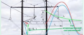
Shock current (iud.) is usually called the highest possible instantaneous value of short-circuit current (see Fig. 5 [L1, p. 11]).
Calculation of short-circuit shock current for a circuit with sequential connection of elements
For circuits with sequential connection of elements, short-circuit shock current. is determined by expression 5.16 [L3, p.48]:
Where:
- Ip.o – initial value of the aperiodic component of the three-phase short-circuit current.
- Ksp – impact coefficient for time t = 0.01 s, determined by one of the following expressions 5.17 – 5.19 [L3, p.48]:
If Xek/Rek > 5, it is allowed to determine the shock coefficient using expression 5.20 [L3, p.48]:
Ta is the decay time constant of the aperiodic component of the short-circuit current, determined by expression 65 [L1, p. 9 and 74] and by expression 5.11 [L3, p. 46]:
Where:
- Hack and Rec are, respectively, the total inductive and active resistance of the circuit from the power source to the short-circuit point.
- ω = 2πf = 2*3.14*50 = 314 – angular frequency (f = 50 Hz – network frequency).
For approximate calculations, the Ta value can be determined from Table 3.8 [L2, p. 150].
Calculation of short-circuit shock current for a circuit with a branched inclusion of elements
For circuits with branched connections of elements, short-circuit shock current. determined by the same formula 5.16 as in the case of a circuit with sequential inclusion of elements:
The impact coefficient is determined by the following expressions 5.17a – 5.18a [L3, p.46]:
When Xek/Rek > 5, the shock coefficient is determined by a similar formula as in the case of a circuit with sequential inclusion of elements:
where: Ta.ek is the equivalent decay time constant of the aperiodic component of the short-circuit current, determined by expression 67 [L1, p. 9 and 74] and by expression 5.13 [L3, p. 47]:
Where:
Hack and Rek are, respectively, the total inductive and active resistances obtained from an equivalent circuit composed of inductive and active resistances, by alternately excluding from it first all active and then all inductive resistances.
For a sequential connection circuit and for a branched connection circuit according to clause 5.3.3 [L3, p. 45].
When determining Ta (Ta.ek), it is necessary to take into account that synchronous machines are introduced into the design circuit by negative sequence inductive reactance - X2(nom) and stator winding resistance at normal operating temperature - Ra.
For asynchronous motors, the negative sequence inductive reactance is taken into account – X2(nom) equal to the supertransient inductive reactance X”.
The supertransient resistance of the electric motor and the supertransient phase-to-phase EMF in relative units can be determined from Table 5.2 [L4, p. 14]:
The x/r ratios for various network elements are given below [L1, p.75].
Calculation of short-circuit shock current taking into account the influence of synchronous and asynchronous electric motors
According to clause 5.6.3 [L3, p.54] short-circuit shock current. from synchronous and asynchronous electric motors is determined by expression 5.16 [L3, p.48]:
where: Ksp – shock coefficient of the engine circuit, determined according to Ch. 5.6 [L3, p.54] and tables 2.74 - 2.75 [L5].
Also, for approximate calculations, the shock coefficient for motors connected directly to the fault location through linear reactors or cable lines can be determined according to Table 6.3 (p. 213) of standard work No. 192713.0000036.02955.000AE.01 “Relay protection of auxiliary network elements 6.3 and 0.4 kV power plants with turbogenerators" Atomenergoproekt.
These motors are combined into one equivalent motor with total power ΣRnom.eng., with average design parameters, the values of which are given in Table 6.3.
Literature:
- Belyaev A.V. How to calculate short circuit current. Tutorial. 1983
- Electrical equipment of stations and substations. Second edition. L.D. Rozhkova, V.S. Kozulin. 1980
- Guidelines for calculating short circuit currents and choosing electrical equipment - RD 153-34.0-20.527-98.
- Calculations of short circuit currents for relay protection. Tutorial. Part one. I.L.Nebrat 1996
- Electrician's reference book. Grigorieva V.I. 2004
All the best! See you again on the Raschet.info website.
Short circuit surge current
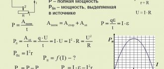
The total short-circuit current reaches its greatest value at the highest values of its components. In § 4.3 it was established that the initial value of the aperiodic current reaches a maximum when the current of the previous mode is zero (no-load), and at the moment of short circuit the periodic component of the forced current passes through its maximum. This condition is accepted as a calculated one.
Maximum instantaneous value of the total short-circuit current – iу
- called shock current.
Let us find the conditions under which the shock current reaches its greatest value for the case when the current of the previous mode was equal to zero, i.e. Im =
0. In this case, the equation for the total short-circuit current takes the form:
(4.16)
and is a function of two independent variables: time t
and switching phases
α
.
The maximum current occurs at α =
0.
For circuits with predominant inductance φк ≈
90°, therefore the conditions for the occurrence of the largest aperiodic component and the condition under which the maximum instantaneous value of the total current is achieved are very close to each other.
Therefore, in practical calculations, the maximum value of the total short-circuit current, which is called the short-circuit shock current iу
, is usually found at the highest value of the aperiodic component, considering that it occurs approximately after half a period, which at
f =
50 Hz is about 0.01 s from the moment the short-circuit occurs .
Rice. 4.6. To determine the short-circuit shock current Thus, the expression for the short-circuit shock current can be written as follows: , (4.17) where , (4.18) which is called the shock coefficient and which shows the excess of the shock current over the amplitude of the periodic component. its value is within the limits, which corresponds to the limiting values Ta , i.e. Naturally, the less Ta , the faster the aperiodic component decays and, accordingly, the smaller the shock coefficient. The influence of this component is felt only at the initial stage of the transition process; in high voltage networks and installations it practically disappears after 0.1...0.3 s, and in low voltage installations it is almost completely unnoticeable. A three-phase short circuit was previously called symmetrical, but this term is strict only to the periodic components of currents in the phases. The aperiodic components of currents and, therefore, total currents in all phases cannot be the same. Under the effective value of the total short-circuit current. understand the rms short-circuit current. for the period in the center of which the moment in time under consideration is located. The value of this current is determined by the expression . (3.14) If in (3.14) the value is expressed through its components and the corresponding transformations are made [1], we obtain , (3.15) where is the effective value of the periodic component of the short-circuit current; effective value of the aperiodic component of the short-circuit current at a point in time. Moreover, according to [1], we can write ; . (3.16) Of greatest practical interest is the effective value of the short-circuit current. during the first short-circuit period, that is, in the time period in which the short-circuit shock current is located. In this case, the effective value of the short-circuit current is usually denoted by . According to formula (3.15), we can write , where (since the short-circuit circuit is connected to a source of unlimited power); . Then or finally . (3.17) Bearing in mind that it can vary from 1 to 2, we obtain that, according to expression (3.17), it can be within the limits . (3.18) |
Determination of instantaneous and effective values of short-circuit shock current
Having analyzed the participation of each SG in feeding the short circuit point, set their operating modes
5.5 Determination of instantaneous and effective values of short-circuit shock current.
If all sources of electrical energy are in approximately the same conditions relative to the short circuit point, then the values of the instantaneous and effective values of the short circuit shock current can be determined by the formulas:
where is the initial supertransient current,
— impact coefficient,
where is the equivalent decay time constant of the aperiodic component of the short-circuit current,
- the resulting inductive reactance of the circuit relative to the short-circuit point in the absence of active resistances,
— the resulting active resistance of the circuit relative to the short-circuit point in the absence of reactance,
ω is the circular frequency equal to 314 1/s.
If the short-circuit point is located on the generator buses or on the high side of the block transformer, or on the load buses, then the instantaneous value of the shock current at the short-circuit point should be determined as the sum of the instantaneous shock currents from the source on whose buses the short-circuit occurred and from an equivalent source that replaces the rest part of the system.
Calculation procedure:
1. Using the equivalent circuit and the results of the transformation in paragraph 5.1. bring the equivalent circuit to a two-beam form:
K
Figure 5.27
2. Find the initial values of the periodic components of the short-circuit current of both beams.
3. Draw up an equivalent circuit into which all elements are introduced with their active resistances. The values of these resistances are found from the known inductive reactance of the element and the ratio taken from Table 5.2.
Table 5.2
| Item name | Attitude |
| Turbogenerators up to 100 MW | 15-85 |
| Turbogenerators 100-500 MW | 100-140 |
| Transformers 5-30 MVA | 7-17 |
| Transformers 60-500 MVA | 20-50 |
| Reactors up to 1000 A | 15-70 |
| Reactors from 1500 A | 40-80 |
| Power lines | 2-8 |
| Generalized load | 2,5 |
4. Reduce the equivalent circuit to a two-beam form and determine the active resistance of the beams.
5. Determine the decay time constants of the aperiodic components of the short-circuit current using the formula:
;
6. Determine impact coefficients.
7. Find the instantaneous value of the shock current at the short-circuit location, as the sum of the corresponding beam currents.
8. It should be borne in mind that the effective value of the short-circuit shock current (Iу) is not the sum of the corresponding currents along the branches. This current is determined as the root mean square value by the formula:
where , is the shock coefficient of the i-th branch,
are the effective values of the periodic and aperiodic components of the short-circuit current of the i-th branch, respectively.
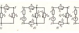
Example 5. For the design diagram shown in Fig. 5.3, calculate the instantaneous and effective value of the impact current of a three-phase short circuit at point “K”.
Since the system and the generator are in approximately the same conditions relative to the short-circuit point, we calculate the shock current from the initial effective value of the periodic component of the short-circuit current. from example 1.
We draw up an equivalent circuit in Fig. 28, into which we introduce all the elements with their active resistances in accordance with Table 2. We calculate.
TO
Figure 5.28
We calculate the instantaneous and effective values of the shock current:
5.6. Determination of the residual stress value at a specified point for time t =0.
Expanding the equivalent circuit (Fig. 24), determine sequentially the values of currents in the branches and voltages in the nodes in relative units. Calculate the voltage value at a given point “M” in named units using the formula:
where is the average voltage of the stage at which point “M” is located.
Having analyzed the participation of each SG in feeding the short circuit point, set their operating modes
Information about the work “Calculation of short circuit currents”
Section: Physics Number of characters with spaces: 32290 Number of tables: 8 Number of images: 23
Similar works
Relay protection and calculation of short circuit currents
32945
10
18
...at a constant operating current. Figure 1 – Distribution network diagram The figure indicates: PGTV – protection against overload by currents of higher harmonics; – temperature indicators, oil and water circulation indicators in the cooling system with an effect on the signal. 1. Calculation of short circuit currents The magnitude of short circuit currents for a number of protections (differential, current cutoffs, etc.) ...
Calculation of short circuit currents, relay protection and automation for cable lines
19651
5
11
… . Preventing the occurrence of accidents or their development in the event of damage in the electrical part of the power system can be ensured by quickly disconnecting the damaged element, for this purpose relay protection and automation are used. The main purpose of a relay protection is to automatically disconnect a damaged element (usually a short circuit) from the rest of the undamaged part of the system using switches. ...
Calculation of symmetrical and asymmetrical short circuits in the electrical power system
13340
4
71
... zero-sequence equivalent circuits 8.4 Determination of currents and voltages at the point of damage K1 8.4.1 Two-phase short circuit to ground Introduction Course work is carried out on the topic “Calculation of symmetrical and asymmetrical short circuits in the electric power system” The work calculates currents and voltages for symmetrical and asymmetrical short circuits short circuits (short circuit). IN …
Issues of reconstruction of the 10 kV line of the Vasilevo substation, with the replacement of oil circuit breakers with vacuum ones, selection of disconnectors and current transformers
82374
14
18
… BК £ Iterm2 ×tterm Selection of disconnectors. Disconnectors are used to turn on and off de-energized sections of an electrical circuit under voltage. The selection of disconnectors is made according to the same parameters as switches, except for the condition of breaking capacity. [3] In accordance with the listed conditions (1.1 - 1.5), we select on the 10 kV side the disconnector RLND - 10/200 ...