Soil resistivity is a value that quantitatively characterizes the property of the earth and soil as an electrical conductor. The unit of measurement for this parameter is Ohm*meter, that is, mathematically, the value is the product of resistance and wire length. This parameter is a special case of the electrical resistivity of materials.
The practical meaning of this value is to determine how effectively grounding of nearby electrical equipment will occur in this particular soil. There are differences between the calculated (theoretical) and measured (practical) values of this parameter. The first is calculated using special formulas, the second is established experimentally.
There are reference data that contain average theoretical (calculated) values of soil resistivity of different types. So, for wet clay this value is 20 Ohm*m, for dry sand from 1,500 to 4,200 Ohm*m, for garden soil - 40 Ohm*m, for chernozem soils - 60 Ohm*m, for coal - 150 Ohm *m.
Resistivity errors and their causes
As can be seen from the reference values given, in some cases the calculated indicators can vary over a very wide range. This happens because theoretical methods cannot take into account the whole variety of factors influencing the level of soil resistivity. Among these factors it should be noted:
- humidity, temperature and other general physical parameters of the soil;
- chemical composition and type of soil fraction (sand, clay, crushed stone, gravel, black soil, etc.);
- the density of the particles that make up the soil adhere to each other;
- the presence and concentration of various substances, including acids, alkalis and salts;
- other parameters that are not taken into account theoretically at all, but still exist.
But in order for the grounding device to be manufactured correctly and subsequently successfully perform its function, accurate values of soil resistivity are required, obtained by electrical measurement and testing.
Grounding resistance.
Grounding resistance (resistance to the spread of electric current) is the amount of “resistance” to the spread of electric current entering the ground through the ground electrode.
ground resistance measurement value is Ohm and it should be minimally low in value. The ideal case is considered if the value is zero, this means that when “harmful” electric currents pass, there is no resistance, which guarantees their COMPLETE absorption by the ground. Since it is almost impossible to achieve the ideal, all electronics and electrical equipment are created on the basis of certain standardized values of grounding resistance equal to 60, 30, 15, 10, 8, 4, 2, 1 and 0.5 Ohms.
To calculate the conductor resistance, you can use the conductor resistance calculator.
When connecting to electrical networks with 220 Volts / 380 Volts, grounding must be provided for private houses with a recommended resistance of no more than 30 Ohms.
grounding resistance (local + all repeated + grounding of the transformer / generator) should not exceed 4 Ohms Without any additional measures, this condition is met if the current source (generator or transformer) is properly grounded.
The standard requirement for grounding a house when connecting a gas pipeline to a house must be met, but it is necessary to carry out local grounding with a resistance of no more than 10 Ohms, due to the use of a dangerous type of equipment (for all repeated groundings, PUE 1.7.103).
The grounding resistance should be no more than 10 Ohms (RD 34.21.122-87, clause for grounding, which is used when connecting lightning rods.
Based on PUE 1.7.101, no more than 2, 4 and 8 Ohms of grounding resistance are required for a current source (generator or transformer), respectively, at line voltages of a three-phase current source: 660, 380 and 220 V or a single-phase current source: 380, 220 and 127 V.
In devices for protecting overhead communication lines (for example, radio frequency cable or local network based on copper cable), the grounding resistance to which gas arresters are connected should be no more than 2 Ohms, this is necessary for their reliable operation. There are also instances that require a value of 4 ohms.
Grounding when connecting telecommunications equipment should have a resistance of no more than 2 or 4 ohms.
The current flow resistance for the substation should not exceed 0.5 Ohm (PUE 1.7.90).
But the above grounding resistance only for normal soils that have a specific electrical resistance not exceeding 100 Ohm*m (clay or loam).
However, if the soil has a higher electrical resistivity, then very often (but not always) the minimum value of grounding resistance by an amount equal to 0.01 of the soil resistivity.
For example, with a resistivity of 500 Ohm*m, the minimum local grounding resistance of a house with a TN-CS system in sandy soils increases 5 times, instead of 30 Ohms, it becomes 150 Ohms.
To calculate the grounding resistance, special methods and formulas have been developed that describe the dependences on the given factors.
The main qualitative indicator of a grounding conductor is the grounding resistance and it depends directly on the following factors:
1. Soil resistivity
2. Configuration of the ground electrode, in particular on the area of electrical contact of the ground electrodes with the ground
Instruments and measurement procedure
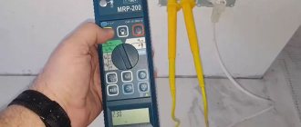
To obtain experimental values of soil resistivity, specialized models of ohmmeters are used: F-4103 and M-416. The first option is used more often, because the second is largely outdated. In addition, in recent years, more modern and easy-to-use models and modifications have been developed and produced.
The process of taking and processing readings from a device for measuring soil resistivity consists of the following steps.
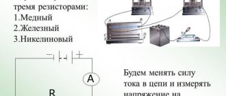
- The electrode of the device, through which experimental voltage is supplied to the soil, is immersed in the soil anywhere in the area. The electrode is connected to the body of a specialized ohmmeter with two terminals.
- The pins of the device are immersed in the ground to a depth of 30 cm to half a meter, and if necessary, they are hammered. The pins are located on the same line on opposite sides of the electrode being measured, at a distance of 10 to 15 meters from it.
- The pins are also connected to the device body by two terminals. After immersion in the soil, a test measurement is made, its results are recorded in the measurement log. If the result is unsatisfactory, the pins and electrode are replaced with terminals.
- Next, a series of at least three readings is taken, which are also recorded in the log. According to the rule accepted in this field, the arithmetic mean of three readings is considered the final experimental result.
- The final experimental value is substituted into the formula for calculating soil resistivity. Calculations are made, the result of which is the desired parameter, expressed in Ohm*m.
To calculate this value, the following formula is used : ρ = 2·π·R·a , where ρ is the soil resistivity (Ohm*m), π is a mathematical constant equal to 3.14 (the value has no units of measurement), R is the average arithmetic of three experimental values (measured in ohms), and - the distance between the pins (measured in meters).
Circuit design
Components
The previously mentioned grounding resistance (Rз) of the circuit is the main parameter controlled at all stages of its operation and determines the effectiveness of its use. This value must be so small as to provide a free path for the emergency current tending to flow into the ground.
Note! The most important factor that has a decisive influence on the value of grounding resistance is the quality and condition of the soil at the site of the installation. Based on this, the charger in question or the ground loop of the charge circuit (which in our case is the same thing) must have a design that meets the following requirements:
We advise you to study Transition Resistance
Based on this, the charger in question or the ground loop of the charge circuit (which in our case is the same thing) must have a design that meets the following requirements:
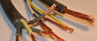
- It must include a set of metal rods or pins with a length of at least 2 meters and a diameter of 10 to 25 millimeters;
- They are connected to each other (necessarily for welding) by plates of the same metal into a structure of a certain shape, forming a so-called “grounding conductor”;
- In addition, the device includes a supply copper busbar (also called electrical) with a cross-section determined by the type of equipment being protected and the magnitude of the drain current (see the table in the figure below).
These component devices are necessary to connect the elements of the protected equipment with the descent (copper busbar).
Differences in device location
According to the provisions of the PUE, the protective circuit can have both external and internal design, and each of them is subject to special requirements. The latter establishes not only the permissible resistance of the ground loop, but also stipulates the conditions for measuring this parameter in each particular case (outside and inside the object).
When dividing grounding systems according to their location, it should be remembered that only for external structures the question of how the grounding resistance is normalized is correct, since it is usually absent indoors. Internal structures are characterized by wiring of electrical busbars along the entire perimeter of the premises, to which grounded parts of equipment and devices are connected through flexible copper conductors.
For structural elements grounded outside the facility, the concept of re-grounding resistance is introduced, which appeared as a result of the special organization of protection at the substation. The fact is that when forming a neutral protective conductor or a working conductor combined with it at the supply station, the neutral point of the equipment (step-down transformer, in particular) is already grounded once.
Therefore, when another local grounding is made at the opposite end of the same wire (usually a PEN or PE bus connected directly to the consumer panel), it can rightfully be called repeated. The organization of this type of protection is shown in the figure below.
Important! The presence of local or repeated grounding allows you to insure yourself in case of damage to the protective neutral wire PEN (PE - in the TN-CS power supply system). Such a malfunction is usually found in technical literature under the name “zero burnout”
Such a malfunction is usually found in technical literature under the name “zero burnout.”