home
Protocol+ program for electrical laboratory
The Protocol+ program allows you to significantly reduce and automate the process of activity of electrical laboratory employees associated with filling out test (measurement) reports, eliminate the costs of drawing up single-line electrical diagrams, lists of defects with recommendations for replacing circuit breakers after checking them and preparing title documentation.
Certificate of state registration of the program No. 2010610081. The key difference between the Protocol+ and similar ones is that the program was created by a test engineer and was refined over several years in order to optimize and facilitate the creation of test reports and single-line diagrams.
The cost of the Protocol+ program is 50 thousand rubles.
New version of the Protocol+ 110 program 06/07/2015
(the 2015 version of the program does not mean that development has stopped and the project has been abandoned. This fact only indicates that all errors over the years have been corrected and customer wishes have been taken into account. The author of the program does not artificially change the version of the program without significantly changing the functionality of the program itself .)
The program provides the following functions:
— correct generation of filling out the “Phase-zero” test report with automatic determination of technical characteristics and response time of protection devices for compliance with RD requirements;
— automatic filling and formatting of the “Insulation Resistance” protocol;
— automatic creation of the “Resistance of transition contacts” protocol;
— automatic creation of the RCD check protocol;
— automatic creation of a test protocol for “Circuit Breakers”;
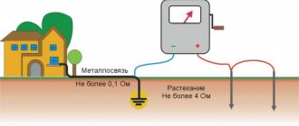
— automatic creation of the “Resistance of grounding devices” protocol;
— automatic creation of a “Visual inspection” protocol;
— automatic creation of a list of defects for the phase-zero protocol with recommendations for elimination;
— automatic creation of a list of defects for the visual inspection protocol;
— automatic creation of title and design documentation for the report as a whole;
— automatic creation of “Single-line diagrams” in DWG format.
System requirements:
— Operating system Windows XP, Vista, 7, 8, 10;
- MS Excel versions 2007 - 2021 (RUS / ENG);
- AutoCAD versions 2006 - 2021 or, not entirely preferably, a FREE domestic analogue of nanoCAD (with limited functionality of the free version) (www.nanocad.ru). (AutoCad and AutoCad LT are different. Diagrams are not drawn in AutoCad LT, because AutoCad developers have disabled interaction with external programs)
Using the program:
The Protocol + program comes with an electronic USB key (details https://www.guardant.ru/products/all/guardant-code/). One key is enough for one organization with any number of workplaces, since the Excel specification is initially filled out, and only then the program creates protocols and draws single-line diagrams based on the completed specification, which takes a few minutes in total. Thus, several operators can simultaneously fill out specifications for different objects, and then alternately create reports using the program.
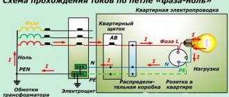
What is meant by the term phase-zero loop?
According to the rules of the PUE, in power substations with voltages up to 1000V with a solidly grounded neutral, it is necessary to regularly measure the resistance of the phase-zero loop.
A phase-zero loop is formed if you connect a phase wire to a neutral or protective conductor. As a result, a circuit is created with its own resistance through which electric current moves. In practice, the number of elements in a loop can be much larger and include circuit breakers, terminals and other connecting devices. If necessary, you can calculate the resistance manually, but the method has several disadvantages:
- it is difficult to take into account the parameters of all switching elements, including switches, automatic machines, circuit breakers, which could change during the operation of the network;
- it is impossible to calculate the impact of an emergency on resistance.
The most reliable way is to measure the value using a verified device, which takes into account all errors and shows the correct result. But before starting the measurement, it is necessary to do some preparatory work.
Protocol on measurements of the “phase zero” circuit
Based on the measurements taken, a special protocol is drawn up. It is used to store recorded readings, as well as to carry out comparative analysis with subsequent tests.
The protocol displays the following information:
- the date of the;
- protocol number;
- purpose of testing;
- information about the organization conducting the tests;
- information about the customer;
- current climatic conditions: atmospheric pressure, temperature and humidity;
- measurement range, accuracy class and type of release;
- meter used for testing;
- recorded readings;
- test result;
- positions, names and signatures of the persons who carried out the measurements and checked the protocol.
Note! If the result is positive, the circuit is allowed to operate without restrictions. When deficiencies are identified, a list of required actions is compiled to restore the required indicators.
Test timing
Electrical networks and equipment are operated in various modes. Over time, there is natural aging of the cable insulation, deterioration of the properties of conductors due to current overloads, voltage deviations, environmental influences, etc. This necessitates the need to periodically check the integrity of the phase zero circuit.
In accordance with the instructions of the PUE, testing of the “F-N” loop is carried out at least once every 36 months, and for electrical networks operated in hazardous or aggressive environments, at least once every 24 months. Unscheduled inspections are also provided in the following situations:
- when introducing new equipment into operation;
- after modernization, prevention or repair of the existing network;
- at the request of the electricity supplier;
- upon request from the consumer.
Frequency of inspections of electrical equipment of residential buildings
Why check the resistance of the phase-zero loop?
Checking is necessary for preventive purposes, as well as to ensure the correct operation of protective devices, including circuit breakers, RCDs and automatic circuit breakers. The result of measuring the phase-zero loop is the practical determination of the resistance of the power line to the machine. Based on this, the short circuit current is calculated (we divide the network voltage by this resistance). After which we draw a conclusion: will the circuit breaker protecting this line be able to turn off during a short circuit?
For example, if a C16 circuit breaker is installed on the line, then the maximum short-circuit current can be up to 160 A, after which it will trip the line. Suppose, as a result of the measurement, we obtain a resistance value of the phase-zero loop equal to 0.7 Ohm in a 220 V network, that is, the current is 220 / 0.7 = 314 A. This current is more than 160 A, so the machine will turn off before the wires and Therefore, we believe that this line corresponds to the norm.
Important! High resistance causes false operation of the protection, heating of the cables and fire.
The reason may lie in external factors that are difficult to influence, as well as inconsistency between the protection rating and the current parameters. But in most cases, it's a matter of internal problems. The most common reasons for the automatic operation of machines are:
- loose contact at the terminals;
- current does not match the characteristics of the wire;
- reduction in wire resistance due to obsolescence.
The use of measurements allows you to obtain detailed data about network parameters, including transition resistances, as well as the influence of circuit elements on its performance. In other words, the phase-zero loop is used for the prevention of protective devices and the correct restoration of their functions.
Knowing the parameters of the circuit breaker for a specific line, after taking a measurement, you can say with confidence whether the circuit breaker will be able to operate in the event of a short circuit or whether the wires will start to burn .
Frequency of measurements
Reliable operation of the electrical network and all household appliances is possible only if all parameters comply with the standards. To ensure the desired characteristics, periodic testing of the phase-zero loop is required. Measurements are taken in the following situations:
- After commissioning of equipment, repair work, modernization or network maintenance.
- Upon request from service companies.
- At the request of the electricity consumer.
Reference! The frequency of inspection in aggressive conditions is at least once every 2 years.
The main task of measurements is to protect electrical equipment, as well as power lines from heavy loads. As a result of the increase in resistance, the cable begins to become very hot, which leads to overheating, tripping of circuit breakers and fires. The value is influenced by many factors, including environmental aggressiveness, temperature, humidity, etc.
ESIS Electrical systems and networks
We will carry out the measurement in 2 stages: 1. External inspection We carry out a thorough external inspection:
- power assemblies and shields
- single-line power supply circuit diagram
- rated currents of circuit breakers and fuses
- sections of outgoing lines
- protection devices for mechanical damage
2. Measurement of the phase-zero loop
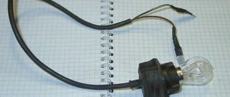
Before measurement, it is necessary to check the tightness of the connection of wires to the protection devices. If the wires are not stretched, then there is no point in measuring, because the obtained indicators will not be reliable.
Measuring phase-zero loop resistance
The goal is to find out the correspondence between the rated current of the protection devices and the cross-section of the wires of the measured circuit.
We measure the phase-zero loop at the most distant point of the measured line.
If it is problematic to determine the farthest point of the line, then it is necessary to measure the resistance of the phase-zero loop at all points of this line.
We write down the measured values in a notepad.
Method for measuring the phase-zero loop. How to take a measurement?
There are several measurement methods:
- open circuit voltage drop method
- method of voltage drop across load resistance
- short circuit method
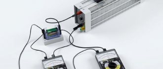
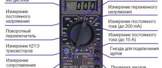
Our electrical laboratory uses the MZC-300 electrical measuring device from Sonel to measure the phase-zero loop, which works using the method of voltage drop across the load resistance. This method is recommended for use by GOST 50571.16-99 (Appendix D1).
I consider this measurement method more convenient and, most importantly, safer.
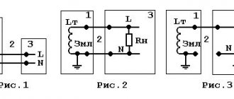
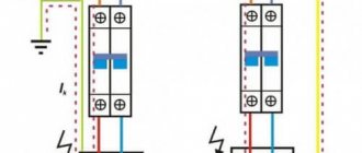
Measurement in operating circuit A (L1) - N
Measurement in protective circuit A (L1) - PE
Checking the protection against short circuits to the electrical equipment frame in the TN grounding system
Checking the protection against short circuit to the frame of electrical equipment in the TT grounding system
Read more about the types of grounding systems in the articles: TN-C, TN-CS, TN-S and.
We measure the loop resistance on an electrical installation that is energized.
How to use the MZC-300 device, in more detail, can be found in the operating manual for this device.
Frequency of measurements
According to the regulatory and technical document PTEEP, measurement of the phase-zero loop is carried out at a certain frequency established by the organization’s PPR system. The maintenance and repair system, which includes cycles of current and major repairs of electrical equipment, is approved by the technical manager of the organization.
For electrical installations in hazardous areas, at least once every 2 years.
If electrical installation protection devices fail, unscheduled electrical measurements must be performed.
How to make a conclusion about measuring the phase-zero loop?
Having measured the phase-zero loop according to the above diagrams, the display of the device will show the value of the single-phase short circuit current.
We compare this value with the operating current of the circuit breaker release or with the fuse link and draw conclusions.
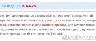
To make a correct and correct conclusion, you must carefully read excerpts from the PTEEP and PUE 7th edition. I combined them into one picture for your convenience.
(click on the picture to enlarge)
For a more clear idea of how to make the correct conclusion when measuring the F-O loop, I will give you an example from personal experience.
Example:
The phase-zero loop was measured in the library room. The measured line is powered from the power assembly by a circuit breaker with a rated current of 16 (A) and characteristic C (more about all types of characteristics).
As I already said in the article, we take the measurement at the farthest point of this line, in our case this is the outlet located in the farthest corner of the library.
The library is powered by the TN-C grounding system. Therefore, we carry out the measurement in the operating circuit (phase - zero).
The measured single-phase short circuit current that the device showed us was 87 (A).
We carefully read the information given in the picture above.
In this example, I will use the point from PTEEP. Those. single-phase current must be no less than 1.1 * 16 * 10 = 176 (A). But our current turned out to be 87 (A) - the condition is not met.
At a current of 87 (A), the electromagnetic protection of the circuit breaker will not work, but the thermal protection will work, the time delay of which will be several seconds (more than 0.4 seconds - PUE). During this time, there is a high risk of ignition or electrical fire.
Conclusion:
In my example, the condition does not satisfy the requirements of PTEEP and PUE. Therefore it is necessary:
- increase the cross-section of the wires of the measured line (as the cross-section of the wire increases, its resistance decreases, which means the single-phase current that will pass under our conditions will increase)
- install a circuit breaker with a lower rated current (by reducing the rating of the circuit breaker, we thereby sacrifice the power of the line)
Phase-zero loop measurement protocol form
The very last stage of measuring the phase-zero loop is entering the measurement values into the protocol.
(click on the picture to enlarge)
(click on the picture to enlarge)
Video material:
General idea of the “phase zero” circuit
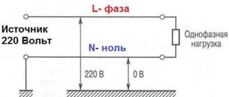
Most electricity consumers are powered by networks with a voltage level of up to 1 kV through a three-phase transformer. To ensure safety, they use a solidly grounded neutral. A current may appear in it due to a phase shift in the windings of the transformer, which are connected in a star circuit.
In the event of contact between the linear and neutral or protective wires, a “phase-zero” circuit is formed. This connection leads to the formation of a short circuit. The circuit may contain connecting wires, switching and protective equipment, which is accompanied by the formation of a certain resistance value.