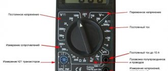
What is grounding?
Grounding is the intentional connection of parts and components of electrical equipment that are not normally energized with an electrode installed in the ground. In this case, it is necessary to define such a concept as resistance to spreading.
When a ground fault occurs, the potential will drop as it moves away from the electrode and will eventually become zero. Thus, the spreading resistance of the ground electrode is a parameter characterizing the resistance of the earth at the location of the electrode installation. The concept of spreading resistance is especially relevant in networks above 1000 V.
Why is grounding needed?
Grounding is necessary to prevent a person from being damaged by electric current if it appears where under normal conditions it should not exist. If you touch the body of a device that is energized, the current flowing through the human body can be fatal.
The need to reduce the potential difference determines the use of protective grounding. In addition, a ground fault leads to an increase in current strength and, as a result, to the activation of protective devices. The standards for protective grounding resistance are regulated by the PUE, as well as by a document called “Rules and Standards for Testing Electrical Equipment”.
It is better to use a megohmmeter to assess other safety factors
For example, insulation resistance. We are not talking about direct danger. That is, if you grab a wire with your hand in which the dielectric properties of the insulation are normal, you will not receive an electric shock.
But there is an additional danger: insulation breakdown under load. This unpleasant fact leads to malfunctions and, what’s more scary, to electrical circuit fires.
A megohmmeter for measuring insulation resistance is a voltage generator and a precision instrument in one housing.
The classic version (still used successfully today) produces voltage up to 2500 volts. Don't be afraid, the currents during operation are negligible. But you only need to hold on to the insulated handles of the measuring cables.
The high voltage potential easily reveals flaws in the insulation, and the meter needle shows the true resistance. Before starting work, you should turn off all voltage-supplying circuit breakers and get rid of residual potential: ground the wire.
To measure the breakdown between wires in one cable, two wires are used. They are connected to the cores of the disconnected cable, and measurements are taken. If the resistance is below normal, the cable is rejected. No one knows when a potential breakdown site will cause trouble.
To measure earth leakage, one wire is connected to the protective ground (in the area where the cable under test is laid), and the second to the central core. The voltage for testing should be higher. If the wire cannot be connected to ground, the measurement is carried out by applying a second electrode to the outer surface of the insulation.
If there is a screen (cable armor), a three-wire measurement system is used. the third wire is connected to the shield of the cable being tested.
The general scheme is exactly this, but each model of the device has its own instructions. Modern megohmmeters with a digital display are even easier to understand than the old pointer meters.
Using a megohmmeter, you can also test motor windings. But this is a separate topic. Information for those who think that all these devices are narrow-profile: using a shunt system, you can turn a megaohmmeter into a precision ohmmeter or voltmeter.
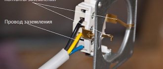
Grounding design.
Grounding is a set of technical protective devices consisting of:
- Grounding conductor - one or more vertical conductors (rods) having electrical contact with the ground and interconnected.
- Grounding conductor (path for fault current) connecting the grounded object and the ground electrode.
A passport is prepared for each grounding. The passport contains the diagram of the grounding device (length and layout of the circuit electrodes), type, soil resistivity, as well as the results of measuring the grounding resistance. A mandatory annex to the passport is an act for hidden work. This act is necessary due to the fact that most of the grounding device is located underground and this act represents a diagram of the arrangement of the elements of the grounding device. If there is no grounding certificate, operation of the facility is prohibited .
Methodology for measuring protective grounding resistance.
To check the grounding resistance, the ammeter-voltmeter method is used, which consists in the fact that a current of a certain magnitude flows through the measured resistance and at the same time the voltage drop is measured. By dividing the current value by the voltage drop, we obtain the resistance value. In principle, the concept of measuring ground resistance means measuring resistance to spreading. Electrical equipment testing rules and regulations specify the minimum grounding resistance calculated from a safety point of view. Standards vary depending on the type of electrical installation (solidly grounded or isolated neutral). The voltage class used also affects the resistance standards.
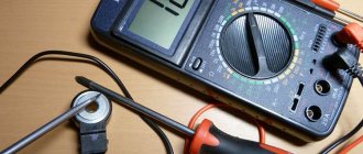
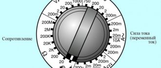
Multimeter measurement
This universal device, if everything is done according to a standard, officially approved method, is not suitable for such purposes, as noted. In practice, a multimeter is used only for an approximate assessment of the grounding condition, identifying obvious breaks, that is, the lack of reliable contact of the corresponding conductor with the ground. How to do this correctly is described here.
Why is this type of measuring device used only in rare cases?
- A large measurement error does not give a true idea of the real resistance value.
- The standard (recommended) method cannot be used, since according to it the device must be connected to 4 points, which are also geographically separated. This cannot be done with a multimeter.
- No specialist will issue an official conclusion based on the results of measurements with such a device (documented). The reason is quite understandable - the regulations do not provide for the use of a multimeter when checking grounding.
However, there are situations when you cannot do without a multimeter. For example, in an area with fairly dense buildings. This does not allow measurements to be taken at large distances from the building. And according to the methodology, it should be within 30±10 m. You can learn more about how to measure resistance using a multimeter from the video:
How to prepare a multimeter
The goal of any measurement is to achieve maximum accuracy of readings. What needs to be done:
- choose a “good” multimeter (from friends, neighbors, and so on). Which one is better to choose for various purposes is described in this article. This means fairly new, and not produced decades ago, undamaged, with the highest possible accuracy class for this type of device;
- replace the battery. An old battery that is partially discharged will only increase the measurement error;
- perform calibration (if provided for a specific model).
How to prepare a workplace
Even if the auxiliary electrode was initially installed when organizing grounding, it still needs to be found. Moreover, if the house was built many years ago, and the area around it has already been redeveloped, improved, and so on several times. Therefore, its “duplicate” must be supplied independently.
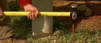
To measure resistance, any metal pin (the same reinforcing bar) with a cross-section of about 5 mm, which is driven into the ground at least 1.5 m at a distance of 7.5 ± 2.5 from the main one, is suitable. It is much easier to find it, especially since the location must be marked (with a sign, a symbol on the wall of the house). Although it is not difficult to determine visually - a metal wire (six or eight) often stretches towards it above the surface.
Where to measure resistance
Between the main ground pin and the newly installed (additional) one. The diagram is shown in the figure.
The measurement result allows you to understand how well the grounding rod meets the requirements that are placed on it. In essence, the total resistance of it and the soil is measured. The fact is that most of it is buried. During long-term use, the metal undergoes corrosion.
- The resistance of the additional rod is preliminarily determined. Its value is not taken into account when evaluating the result.
- The grounding R value should be Measured with a megohmmeter
The measurement principle is the same. The differences are only in some points.
- To obtain the most accurate readings, the device must be installed in a strictly horizontal plane. Skewing along any of the axes is not allowed.
- Preparing a megohmmeter (grounding resistance meter) comes down to checking it for suitability for measurements. This is quite simple to do (example: model M416).
- Switch to “Control”.
- The button is pressed and the handle is rotated. The arrow should be at 5 (±0.3). If the reading is different, the device is rejected.
- How to correctly connect a wire grounding resistance meter to the terminals, depending on the measurement circuit, is shown on its body.
There are quite a few methods for measuring ground resistance. They involve the use of various devices and circuits, and the optimal decision is made individually for a specific circuit. But for self-diagnosis of his condition at home, the two described above are sufficient.
If there are doubts about the correctness of the determination of the results, a large error, and so on, you should contact a professional. Grounding, given that it is an integral part of the power supply circuit, should not be neglected.
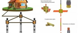
The procedure for measuring grounding (resistance to spreading of the ground electrode).
To carry out the test, in addition to the device, it is necessary to have two electrodes (current and potential) with wires of sufficient length; as a sample, you can offer a piece of smooth fittings or round pipes. Depending on the complexity of the ground electrode design, resistance measurements are carried out using two different schemes:
- Simple (single) grounding conductor. A “linear” electrode connection scheme is used. The potential electrode is installed at a distance of at least 20 m from the ground electrode, and the current electrode is installed at least 10-12 m from the potential electrode.
- Complex grounding conductor. It is used when a simple circuit is not applicable, due to the fact that when calculating the grounding resistance it will not meet the minimum permissible standards. It consists of several vertical rods driven into the ground, electrically connected to each other (by electric welding to reduce the transition resistance). This device is called a ground loop. In this case, it is necessary to determine the largest distance (diagonal) of the protective ground loop. The potential electrode must be driven in at a distance equal to five diagonals from the point where the grounding conductor is connected. The current probe is clogged no less than 20 m from the potential probe. The measuring device must be located as close as possible to the ground terminal.
Why is it necessary to measure grounding?
The operating principle of protective grounding loops is based on the main quality of the electrical flow of electrons - to pass through conductors with the least amount of reaction force. The average resistance of the human body is 1 kOhm. In accordance with the rules for arranging electrical installations, the nominal value of grounding resistance cannot exceed this indicator. According to the standards, 4 ohms are acceptable.
The main goal of the protective periphery is to remove accumulated potentials from the human body and prevent damage. On the body of faulty equipment, for example, as a result of an insulation breakdown, negative electrons accumulate, which are ready to pass through any material. When a hand touches the casing, they rush into the ground through its body. If the magnitude of the current is small, then a person can get away with only an unpleasant sensation and shock, but at high currents of more than 100 mA, the voltage can cause irreversible changes in the body.
Why do you need to check grounding?
Note ! Grounding can reduce the risk of injury to a minimum. The current will flow through materials with less than human resistance.
You may be interested in this Features of a pointer multimeter
For this reason, it is necessary to regularly check the safety circuit for compliance with established standards. This simple preventive measure can help prevent injury and death. In the event that a device for measuring ground resistance ratings shows an excess of the calculated values, the intervention of specialists who are able to repair and put in order the protective circuit is necessary.
The procedure for carrying out measurements.
Since currently the most common measuring instrument is the M-416 ground resistance meter, in the future this measuring instrument will be considered as a sample. This device belongs to a system in which the measuring principle is based on the compensation method. It is prohibited to use instruments for testing that do not have a valid verification stamp, the results of which must be entered in the passport for the measuring instrument.
- Check the presence of batteries in the battery compartment, making sure that their voltage is within normal limits;
- Calibrate the device by setting the range switch to the 5 Ohm (control) position, and use the slider handle to set the arrow as close to the zero mark as possible. In this case, the scale should read 5 ohms;
- Disconnect the circuit from the grounding conductor;
- Connect the device to the corresponding electrodes;
- Having carefully cleaned the terminal of the ground electrode being measured (in order to eliminate the influence that the transition resistance may have on the final result), connect the device to it.
Note: Depending on the planned ground resistance indicators, the measurement device must be connected using a two- or four-wire circuit. The first is used if the expected resistance is more than 5 Ohms, and the second is used for measuring lower values (in this case, the paths for passing current and measuring the potential difference are separated to eliminate the influence of the resistance of the connected wires during measurement). In this case, connection to the ground electrode is carried out by two conductors. The device passport contains visual drawings that will allow you to make connections without errors.
- Set the range switch to the position corresponding to the highest sensitivity (X1) by pressing the “Measurement” button, and use the regulator to set the arrow to zero. In this case, the desired result of checking the resistance of the ground electrode will be reflected on the rheochord scale. If the arrow does not set to zero, you must use the switch to select another range and multiply the flux readings by the appropriate multiplier.
Note : If the measurement is carried out with a tester or multimeter, there is no need to select a multiplier - these devices have the function of automatically selecting the scale limit. IMPORTANT! After measurements, if the grounding resistance is within the normal range, it is necessary to reconnect the grounding conductor to the ground electrode!
Devices
As mentioned above, multifunctional testers are not very suitable for professional measurements, since they give approximate results and are not able to generate the voltage of the required value. To obtain accurate indicators, the well-known M-416, MS-08 and other modern devices are used.
Devices are divided into:
- analog;
- digital.
The operating principle of induction testers is based on the compensation technique. They are distinguished by reliability and durability. However, a significant disadvantage of such devices is the insufficient accuracy of the division scale. They are resistant to external interference and easy to operate. The process of calibrating the device is based on setting the resistance to absolute zero. Such devices are designed to work with ratings from 0.1 to 1500 Ohms.
Electronic testers are superior to analog ones in accuracy and functionality. But if there are electronics inside, they are sensitive to external interference, which can not only affect the final measurement results, but also damage the device itself. Therefore, they require more careful and careful handling. The accuracy class of electronic testers is much higher than that of induction ones. The devices show results down to tenths and hundredths of units, which in some cases is very important.
You might be interested in cable wiring diagrams
Tester M-416
M-416
The M-416 brand meter is designed to take readings from 0.1 Ohm to 1 kOhm. The operating voltage from the device's power supplies varies from 3.8 V to 4.5 V. Since the indicator is a pointer, it is important for the device to remain horizontal. Therefore, before starting testing, it must be placed on a flat surface. Next, set the switch to the 5 Ohm position and, using the slider handle, bring the arrow as close to the zero mark as possible. In this case, the slider scale must accurately show the measurement mark equal to 5 ohms. Deviations of 0.35 units are allowed.
Upon completion of calibration, the circuit is disconnected from the grounding conductors. During testing, the device must be placed next to the control grounding conductor. This will help reduce measurement error caused by transfer resistance. The auxiliary grounding rod and probe are installed at a distance of 10 and 20 meters. The rods must be immersed to a depth of 500 mm.
They need to be hammered in with even and clear blows to prevent swaying. This will also help eliminate the additional error of the transition resistance between the soil and the metal. For soils with high values, the device will show approximate results. To increase accuracy and reduce error, the area around the rods is watered.
Device IS-10
IS-10
The IS-10 electronic device is designed to test the resistance of grounding structures and metal connections according to the 2x, 3x and 4x scheme using probes. To measure specific values of soil resistance, the device allows you to enter data on the distance between the control electrodes. The range of distances is from 1 to 10 meters. The operator has the opportunity to independently enter them into the device menu. Taking into account the entered parameters, the result is displayed on the screen as 1 Ohm per 1 meter.
The device allows you to work with a current of 250 mA and a frequency of 124 Hz. Using the knob, the user adjusts the nominal values with which he intends to work: 1 to 999 mOhm, from 1 to 9 Ohms, from 10 to 99 Ohms, from 100 to 999 Ohms, and from 1 kOhm to 9 kOhms. The accuracy of the readings is hundredths of units with an error of 3%.
Unlike the M-416, the IS-10 tester has a liquid crystal monochrome screen. The electronic filling of the device is equipped with a built-in memory, where up to 64 measurement results are stored. There is a protective circuit against incorrect connection, which will not allow it to burn out at high currents, including protection against the sudden appearance of voltage. The device case is shockproof and meets the degree of protection against dust, moisture and shock IP42.
Meter CA 6412
CA 6412
The CA 6412 tester represents a new generation of the measuring current clamp family. The device body is made of a special material that allows it to be used in adverse conditions. Each part of the test head is placed in a closed casing, which provides them with the necessary strength when working on complex objects. The manufacturer has equipped the device with additional protection against strong vibrations, shocks, moisture and dust.
You may be interested in this Welding machine for welding wires
The design of the device is very simple. To operate, it does not need wires or probes like the devices described above. The tests do not require installation of additional electrodes. The measurement range is from 0.1 to 1200 Ohms at a current value from 1 mA to 30 Amperes. The device displays the results obtained on a monochrome liquid crystal screen. The device is equipped with a self-test function and indication of network interference. Withstands overload current up to 200 A for 30 seconds and has a dielectric strength of 2500 V.
Tester 1820 ER
1820 ER
The 1820 ER portable ground resistance tester allows you to measure step voltage. The device allows you to not disable the circuit circuit when working with a test current of 2 mA. The kit includes probes and cords. The measurement limits are adjusted by the handle and are 20, 200 and 2000 Ohms.
The error of readings does not exceed 2%. The accuracy is 0.01 for 20 ohms, for 200 the tolerance is 0.1 ohms and for 2000 the tolerance is 1 ohm. The test signal is 2 mA with a frequency of 820 Hz. To test the grounding loop, electrodes are also used, which are driven into the ground at a certain distance. Their arrangement can be simple or complex, that is, using several pins.
Measuring device SEW 2705 ER
SEW 2705 ER
Portable device SEW 2705 ER for measuring soil resistance up to 1 kOhm. The two-wire measurement circuit provides rough results, the three-wire provides more accurate indicators. Therefore, it allows you to check step voltage up to 30 V.
With a test current of up to 2 mA, disconnecting the protective grounding circuit from the power voltage network is not required. The design of this device uses a dial indicator. The error of readings does not exceed 2.5%. The resistance test limits are 10, 100 and 1000 Ohms, for a voltage of 30 V with a frequency of 40-500 Hz. The device body is shockproof and waterproof, made in accordance with modern standards.
Registration of measurement results (protocol).
After completing the measurements, you need to draw up a protocol of the measurement results. The protocol is a form of a certain form, which reflects the name of the object, the installation diagram of grounding rods and their connections (for this you will need a passport of the object and an act for hidden work). The protocol should also reflect the ground loop diagram and the method by which the measurement was carried out. The protocol must include a column indicating the device or tester (its type, serial number, etc.) with which the test was carried out. The results obtained during the measurement are entered into the grounding device passport. The transient resistance test report is presented separately. Transition resistance (also called metal bonding) is the possible losses along the current path associated with welding, bolting and other connections of the entire ground loop. This test is carried out with a special tester - a microohmmeter.
IMPORTANT! Only a testing laboratory accredited in the system of standardization bodies can conduct tests and issue a protocol for measuring grounding resistance. After completing the measurements, a corresponding report is drawn up, and the grounding device is considered suitable for use.