Everyone who installed them is simply amazed how they lived before without such a convenient and effective solution.
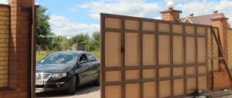
Any sliding gate cannot be compared with this device. And in terms of safety precautions, they are many times inferior to him.
We will not consider the process of making gates yourself, especially since their prefabricated versions can be easily found and ordered from professional manufacturers.
Let's focus specifically on the moments of installing individual elements, connecting and setting up the automation system.
Mortgage for sliding gates
The installation of sliding or sliding gates requires the opening to be prepared accordingly. What does this work involve?
Firstly, this is the preparation of the foundation or mortgage. It's like making a foundation for a house. This mortgage is the main anchor of the entire structure.
The mortgage is a heavily concreted 16th channel. The height of the channel is the zero of the future entry.
If the entrance will subsequently be tiled, lay the channel above the existing zero mark to the height of the tiles. In order for the concrete to completely fall under the channel when pouring, the formwork must be made level with it.
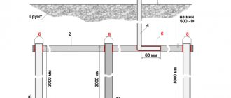
The depth of such a foundation depends on the depth of freezing in your region. For example, in Moscow and the Moscow region, experts deepen it to 1.5 m, plus 20 cm per sand cushion.
Mistake #1
If you do not take this into account, then the foundation may subsequently bulge, disrupting the free movement of the gate, or even wedge it.
Capital polymerization of concrete occurs within 28 days. For quality work that lasts for centuries, it is advisable to maintain these deadlines and install the gate on a concrete base that has fully gained its strength.
However, few people have the patience for such periods, but it is necessary to withstand at least a week.
Before pouring concrete, clearly align and secure the channel with additional pieces of reinforcement so that it does not move to the side.
At the same time, the mortgage itself does not have to be scalded with a whole web of metal.
This will not add any special strength and it will not help in any way if the depth is insufficient and heaving is tangential. And such a force can reach several tons per 1 m2.
It easily lifts and breaks the walls of garages and houses, not to mention any gates.
Therefore, vertical reinforcement bars 12-16mm2 are quite sufficient.
Calculate the length of the pit for the foundation using the formula: the length of the entire opening divided in half.
For example, your gate width is 4m. This means you need to prepare a pit about 2m long. Its width should be 40-50cm.
A standard hole for such a gate requires about 2m3 of concrete.
The gates themselves never arrive ready-made. The sash will have to be assembled on your site.
On the factory product, all technological holes are already prepared, so if you follow the instruction diagram, you should not have any problems with installation.
When assembling, the most important thing is to clearly control the geometry.
Mistake #2
Here you need to adhere to the following rule - all diagonals of the sash should not differ from each other by more than 5 mm.
The central part can be filled with various materials:
- corrugated sheet
Fastened with self-tapping screws or rivets.
To prevent the sheets from rattling at the joints when the gate moves, all cracks and spaces can be filled with silicone sealant. Or just put a seal on it.
- fence
- blind filling, panel type
To strengthen the entire structure, a cable tie is often used. It can easily adjust the required correspondence along the diagonals.
Mistake #3
If you are welding a profile as a jib, be careful! With a lack of experience, welding seams can lead to metal and the lower guide.
And the gates will start knocking in these places, like a train on rails.
Review of brands used to connect automatic gates
VVG – suitable for powering an electric drive or automatic gate control unit. The purpose of VVG is precisely in the transmission and separation of electricity in stationary mechanisms at a rated alternating voltage of 660 and 1000 V, with an alternating current frequency of 50 Hz. It can be laid in damp and dry rooms, in the ground, on vertical and horizontal sections, with vibration, but It is necessary to protect the cable from mechanical damage. However, VVG is rarely used when connecting gates, since it does not have sufficient flexibility and is more difficult to pull into pipes with bends.
PVA is the most commonly used brand for gates.
Many craftsmen connect all elements of the gate with a PVS cable: from the drive to the antenna that amplifies the signal from the control panel. The brand has sufficient flexibility, it is easier to pull it into pipes. The PVS brand refers to connecting wires, used for connecting electrical machines, household appliances and tools at a rated alternating voltage of up to 380 V, at a frequency of 50 Hz. The current-carrying core is made of copper, flexible, insulation and housing are made of polyvinyl chloride plastic. It is resistant to corrosive substances, mold fungi, and mechanical stress.
PVS or VVG - what is the difference and which is better?
— read our article for a detailed review and comparison of the two most popular cable brands.
MKSh – installation cable, excellent for connecting photocells on gates. used for reliable connection of electrical devices with rated alternating voltage up to 500 V, at a frequency of up to 400 Hz. The current-carrying core is made of tinned copper wire, the insulation and housing are made of polyvinyl chloride plastic, the wires are twisted in the cable. The cable is resistant to mechanical stress and vibration.
Photocells can also be connected to signal intercom cable brands such as KSPV, SHVEV. If these brands are not available, then the photocells can be connected with a regular PVC cable.
RG58 – coaxial cable for connecting an antenna. To improve the signal of the gate control panel, an antenna is used, which is connected with any antenna cable.
Support rollers - which ones are better and how to install them
After you have assembled the frame, you begin to secure the rollers on which the sash rolls.
Mistake #4
Never use plastic rollers.
Here you can only consider options with steel ones. Don’t be fooled by manufacturers’ advertisements that polymer rollers are smoother and quieter.
If there is vibration when moving along the guide, it will still be transmitted. And don’t forget about our winter operating conditions.
At extremely low temperatures, plastic rollers become less durable and will begin to collapse upon impact.
Roltek has very good reviews regarding the quality of the videos.
It is extremely important that the bearings have low temperature grease.
They should be reinforced - 301st and not 201st, or 303rd, not 203rd.
The larger size is designed to carry more weight, which means they are more reliable and able to withstand the worst operating conditions, even if the guide geometry is disrupted.
When installing the rollers, you must first mark their installation locations on the channel. Place them on a plane and roll the guide.
A mandatory solution when installing rollers is the use of adjusting bolts.
Mistake #5
The fasteners must be attached to the channel through them, and not through the roller platform itself.
Since for any deviation of the concrete base by only 0.5 cm, the gate will go away by 4-10 cm.
With bolts, during operation you can easily make adjustments in any plane using a regular wrench.
After you have rolled the collar onto the roller supports, they need to be leveled.
Mistake #6
Do not under any circumstances lubricate the rollers or the beam on which they run.
As a result of such amateur activity, sand and dust get clogged there, gradually turning into an abrasive, and systematically grinding down the surfaces of these two important elements.
To install the upper and lower traps, plus the upper bracket against lateral swing, you will need additional supports (arrival post, cover plate). Usually this is a pipe 60*40mm or 60*30mm.
Weld them through the mortgages to the concrete fence posts.
And already to them, you mount these same traps and brackets.
Catchers must be made of steel with a thickness of at least 3-4mm.
To avoid a blow at the very end, and the gate closes completely silently, you can use an elastic band as a gasket if you don’t have factory ones.
Although many smart drives (Nice, Hormann) are themselves capable of stopping the sash in a given place, knowing its length.
Mistake #7
Remember that the lower catcher is installed last, when the gate is level, trimmed and in its working position.
This trap is mounted in such a way that when the canvas enters it, the gate rises a couple of millimeters in order to unload the support rollers.
In this case, they will last much longer.
Mistake #8
Never attach a utility pole directly to a column using anchors without anchors.
In a couple of years, due to wind and shock loads, all this will come loose and the fasteners will tear out. Initially, the embeds must be welded to the steel central column.
If you forgot about this, then do the fastening with at least a chemical anchor.
Benefits of using modules
Installing these devices makes it possible to refuse personal cards, chips, key fobs, and remote controls. In addition, the use of GSM modules significantly simplifies the performance of security functions: a pass to a fenced area can be provided even if you are at a certain distance.
The device is easy to configure, making it highly functional and easy to use. Numbers can be deleted from memory or added within the allowed number. Some modern manufacturers also offer modules with the ability to configure and restrict access for certain hours, days, as well as in case of non-payment of the rental amount for a parking space, as well as in other cases.
Equipping gate and barrier structures with modern GSM modules allows you to maintain logs of visits and departures from the territory. With a sufficiently large flow of road transport, such control is much more convenient and functional.
As for financial savings, the cost of one GSM controller is approximately comparable to the cost of three remote control panels. If the system is used by a large number of subscribers, then automation through modules is much more profitable and economically feasible. To control the module, you can use a mobile operator SIM card, which is configured only to receive incoming calls. This will eliminate the need to pay regular subscription fees for using communications.
Installation and adjustment of the rack
On high-quality factory products, its installation can be done without welding at all. It comes with a special C-profile.
Fasten it level through the self-tapping screws at the bottom of the gate, and then insert the bosses into the grooves.
Move them each to their place and tighten the bolts.
If you do not have such technological fasteners and have to do everything the old fashioned way using welding, then follow the following instructions.
First of all, place the drive itself on the foundation channel and look at the height where the sprocket will be located. You may even have to increase the height of the platform to get everything to line up perfectly.
Only after this do you fasten the drive to the bolts, but do not tighten it too much .
The toothed racks are 1m long. Each of them has an oval hole.
These same bosses are inserted into it - the wide side towards the rail, the narrow side towards the gate.
Initially, place them in the middle and tighten them. Next, unlock the drive, open the gate as much as possible and try on the rack so that the limit switch can subsequently fit between its end and the gear.
In this position, weld the first boss.
You move the gate, just short of reaching the last boss, and grab it. At the same time, make sure that the first and last are at the same level.
Lastly, weld the middle boss. All this time the rack lies on the gear.
Roll the gate further and install the next rail.
Mistake #9
The most important thing here is to correctly connect the two slats to each other.
To accurately adjust the teeth between the two upper ones, place another free strip or a piece of it underneath, then all the teeth will match perfectly and there will be no clicks or knocks when the gate moves.
The process is repeated with all sections of the slats. After you've grabbed everything and rolled the gate back and forth, you can finally scald the whole thing.
Mistake #10
It is not recommended to do this strictly in the order of the bosses.
First, brew the first one, then the one in the middle of the entire collar, then the last one. And so on. In this case, there is less chance that the metal will move.
At the same time, some advise welding the rail to the lower profile of the gate, and not to the guide that runs along the rollers. Otherwise, if you lack experience, everything will bend in an arc and the guide will take the shape of a banana.
In addition, the gate profile lasts much longer than the bottom beam and when replacing it, you will not need to redo the bottom rail fasteners. Most often, the beam “dies” at the end of winter or beginning of spring.
The main enemy of sliding gates is snow. Therefore, always remove it from the rollback side. At a temperature of +-1C, the snow freezes and crushes the beam from the inside.
She, in turn, begins to break the rollers. The best remedy for snow is to make a pencil case into which the gate will fit. Well, or splurge on a warm floor for the street.
Many people talk about the correct gap between the gear and the rack. How is it regulated and set? Very simple.
Open the gate and loosen the first bolt on the boss so that it takes its position on its own. After that, lubricate the thread and tighten it.
Without lubrication, after 5 years the thread rusts and the bolt breaks off at this very place.
Next, move the collar to the end of the first section of the rack, loosen and tighten the third bolt. After that, the one in the middle.
Do the same with the second and other slats, gradually moving the gate. And at the very end, you thoroughly tighten the motor fasteners, which were not tightened too tightly before.
As a result, you will get the same gap recommended by the manufacturers between the rack and the gear itself. The most important thing is that the rack does not put pressure on the gear. If there is no visible gap, but it just lies freely on the gear, that’s also normal.
With this the mechanical part is completed, you can begin installing and configuring the electric drive.
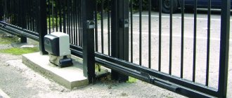
The operating principle of the sliding gate drive and its design
Structurally, the drive includes several basic elements, without which its operation is impossible.
- Engine. It is electric type and has a drive gear.
- Gearbox. Depending on the model, either liquid or grease lubricant can be used.
- Control block.
An interesting feature is that the electric drive firmly locks the gate in the closed position; it cannot be moved manually. Thanks to this, there is no need to install an additional lock; in any case, only someone who has a control key fob can open the structure.
The work process is very simple. The electrical filling of the control unit, as well as the clutch, controls the force transmitted by the rack to the gate structure.
Having become familiar with the operating principle of the drive and its structure, you can begin installing the automation.
Gate installation
The reliability and durability of the gate directly depends on how professionally they were installed. Gate installation is a job for experienced professionals who know the intricacies of each stage.
The first stage consists of building a foundation and installing special support pillars. They must be installed below the soil freezing level and firmly secured. The base must be installed on the side of the gate in the direction in which the leaf will move. To do this, a pit is created into which a pre-welded frame is lowered. The frame is concreted.
After this, the gate frame is assembled and upholstered with the selected material. Finally, the canvas is installed on the frame and, if necessary, connected to an electric drive.
Instructions for connecting swing gates: the main information is available
. We are engaged in the installation of fences, gates (including automatic ones), installation of poles and power lines throughout Moscow and the Moscow region. Call from 09:00 to 21:00 daily.
Automating swing garage or street gates is the dream of many, but now it is not something impossible, so to speak, out of the realm of fantasy. Purchasing a linear automation set has become much easier and more affordable, so although not everyone can buy a set of drives with fitted fittings, the majority can still buy it. As for the installation of automation, the instructions for connecting swing gates included in the kit allow you to do everything yourself, as well as the manufacture of a swing double-leaf structure in general.
Linear automation set
For swing gates, it is necessary to do wiring, which is considered somewhat more complex than for sliding (sliding) gates. Electrical wiring must be thought out in advance - preferably at the stage of concreting and laying support pillars. In this case, you will have the opportunity to hide all electrical cables in the supports, which, in addition to the aesthetic appearance, will also additionally protect the electrical wiring diagram.
Open control box
Typical terminal contacts on the swing gate automation control unit can maximally clamp a wire with a cross-section of 1.5 mm without additional tricks. It must be taken into account that some branches will have to be twisted and then only clamped into the terminal, and the terminals of photocells are even smaller.
Electrical installation work for linear drives
It is recommended that all wires going to the control board for linear drives of swing gates come out in protective plastic corrugations from the installation site of the control unit housing.
Wiring in plastic corrugations
Features and cable routing
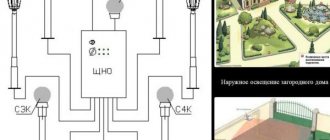
According to the diagram below, it is necessary to consider all the elements of the connection diagram, their features and installation work.
Scheme of preparing the opening for installation of the device
Attention! The red lines in the diagram indicate the wires necessary for the operation of the swing device, and they should be laid. All cables come to the control board (indicated by a green rectangle), and the free ends must have an additional 1-1.5 m. Place the block on the side where it is easier to supply 220V power. Place all elements into the block with corrugations from below to prevent water from entering.
The first electrical cable comes from the control unit, it is made from a PVS 3x1.5 cable, and is directed from the drive to a 220 V power source - a socket or machine. Professionals recommend installing reliable voltage stabilizers on automation systems.
The next cable goes to the signal lamp, 2x0.75 or 2x0.5 will do. If you take a smaller one - nothing, the amperage of the lamp is small. This cable is laid from the control unit to the top of the support pillar closest to the drive; it is also better to hide it in it. If there is a decorative cap on the rack, then the wire is brought out directly to the front plane under this “hat”.
Power supply wires for electric drives must be three-wire. The wiring should exit at a height slightly lower than the electric drives themselves. Be sure to take a flexible and multi-core cable, preferably PVA No. 3x1.5. Be sure to protect the wire of the gearbox closest to the unit with plastic corrugation. To facilitate installation in several places, fix the corrugations on the support with special fasteners. If the pillars are made of metal prof. pipes, then the electric cable should be brought inside and brought out in the immediate vicinity of the swing drive.
For the second drive, located on the farthest pole from the control unit, also take a three-core PVS 3x1.5 cable. Place the wire under the opening; for convenience, route it out in the same corrugation as the photocell wiring.
Connecting cables to the drive
Important! Connect the swing gate drive according to the connection diagram and put the plastic housing cover back on the motor. Using a flathead screwdriver, screw on the stem guard.
Power supply to photocells
Most often, most of the difficulties arise at the stage of wiring the photocell cables, so you should understand it in more detail. Wiring photocells is best done from a 4x0.22 intercom signal cable.
The first thing that can cause difficulties when installing photocells is the location. Usually they are mounted on the ends of the supports so that they are at the same height - approximately 50-60 cm from the ground.
For swing gates, it may be useful to install an additional pair of photocells. It is especially important if your gate is not transparent and solid - you cannot see who is behind it. These photo-elements are located behind the gate structure at a distance slightly greater than the length of the frame of one leaf. To install them, the racks are concreted - the simplest option is to take a 60x30 mm pipe and lay the wiring to the control unit. The control contacts of these photocells are placed on the STOP and GND terminals; the jumper located there must be removed. In a standard automation set, there is only one pair of photocells, so if the above-described scheme is interesting to you, you will have to separately purchase 2 more elements that can work with the existing automation system.
Connection diagram for photocells: the one closest to the control unit (receiving part), designated RX, is equipped with a 4-wire wire, where 2 wires are for power supply and 2 are for controlling contacts. In the diagram, the wire is designated No. 4x0.35 and is directed from the pole to the gearbox. Many people make the mistake of installing not a 4-core cable, but a 2-core cable. If possible, the wire should be hidden in a support, leaving a small free end within 15-20 cm. Otherwise, you need to secure the wire to a pole. Typically, the wires are laid in brick joints and sealed with concrete mortar.
Option for placing automation elements
Power the photocell of the column farthest from the drive (designated TX) with a 2-core cable (in the diagram - 2x0.35). Do the wiring with the same 4x0.22 signal wire, using 2 wires or all 4 wires, but twisted in pairs. Lay the photocell wiring under the opening, leading out in the same corrugation with the gearbox power supply. Be sure to provide reliable protection for it, as vehicles will pass from above.
Automation of double-leaf portal
rusograda.ru
Sliding gates: types of structures, drive options and installation features
Having decided to buy sliding gates, the owner is faced with certain difficulties - the choice is very large, and each type of gate has its own characteristics that must be taken into account. In this article we will tell you how to choose the right sliding gates, how different types differ from each other and what to look for when purchasing.
